Sliding Mode Control for Robust 3D Trajectory Tracking of Quadcopter Unmanned Autonomous Vehicles
Cai Wen-qi, Kordabad Arash Bahari
(Department of Engineering Cybernetics, Norwegian University of Science and Technology (NTNU),Trondheim 7491, Norway)
Abstract: Recently, unmanned autonomous vehicles (UAVs) have attracted a lot of attention in both military and civilian fields, where the trajectory tracking mission has been a popular research topic. In this paper, a robust Sliding Mode Control (SMC) is proposed for controlling a quadrotor UAV for 3D trajectory tracking in the presence of perturbations and parameter uncertainties. The nonlinear dynamics of a quadrotor with 6-DOF is first established. Then, a sliding mode controller with mass, inertia, and stiffness uncertainties is designed. The 3D tracking effectiveness of the controller is verified by modeling simulations in Matlab Simulink and Universal Mechanism software systems. Finally, further physical verification is done using a Pelican quadrotor platform with perturbations applied to the horizontal and vertical axes to verify its robustness. Both the simulation results and the practical implementation results show that the tracking effect and the robustness of the quadrotor UAV for a given trajectory are satisfactory, confirming the correctness and effectiveness of the proposed SMC control algorithm.
Key words: quadcopter unmanned autonomous vehicles (UAVs); sliding mode control (SMC); 3D trajectory tracking; robust control
Currently, Unmanned Aerial Vehicles (UAVs) are used for many tasks: search, rescue, environmental monitoring, surveillance, and inspection. With the help of UAVs, it is possible to easily enter environments that are difficult for people or manned vehicles to enter. This is especially true for extreme situations: firefighting,reconnaissance etc[1]. UAVs are becoming more popular in the form of multi-rotor devices, more commonly a quadcopter, which is a platform with four rotors.Compared with helicopter-type UAVs with main and tail rotors, quadcopters offer many advantages—reliability and simplicity of design, greater stability, compactness and maneuverability, light take-off weight, and greater payload quality. A quadcopter has four engines with propellers that generate thrust. The axis of the propeller and the angle of the blades are fixed, and only the rotational speed is adjusted, which significantly simplifies the design. Vertical movement is carried out by a synchronized change in the rotational speed of all propellers; for horizontal movement, it is necessary to tilt the quadcopter, which is achieved by a corresponding change in the rotational speed of the different propellers,which produces the moment required for tilting. The opposite direction of rotation of the screw pair ensures the compensation of the drag torque. Currently, such devices are quite widespread and versatile, but this use is primarily limited to the “manual” remote control mode from the operator console.
Researchers have been working on the problem of trajectory tracking control in UAVs along known trajectories. Various methods are discussed and proposed. Kumar et al[2]use a linear quadratic controller to successfully solve the problem of stability during hover, but not suitable for significant nonlinearity and cross-coupling. In literature [3], an algorithm for tracking the trajectory of a quadcopter based on a PD controller and backstepping with a correction filter is proposed. In literature [4], a neural network-based nonlinear controller is proposed, and in literature [5], a“real-time” algorithm for trajectory planning and collision avoidance is proposed. In literature [6], an adaptive position tracking algorithm for vertical take-off and landing under limited external disturbance is considered. The authors in literature [7] propose a control system that realizes the movement of the quadcopter along a straight line connecting the start points and end points of the trajectory at a given speed and a given altitude above the Earth's surface. In literature [8], an algorithm for moving a quadcopter along any trajectory in space is considered, where the quadcopter is able to follow a moving object with known coordinates and velocities.
In addition to the above methods, a commonly used method for quadrotor UAV trajectory tracking is the sliding mode control. Sliding Mode Control (SMC) is a powerful nonlinear strategy that ensures robustness despite parameter uncertainty in the model[9-10]. A number of papers have been published applying SMC methods to the position and attitude tracking problems of quadcopters and ensuring the robustness to external disturbances. The author in literature [11] applies this method to the quadrocopter with the motivation to theoretically exploit the robustness of the method with regard to model uncertainties and disturbances. The problem of chattering, which occurs with SMC by switching along with the sliding mode, is prevented by a smooth approximation of the signum function in literature [12]. In literature [13], the authors compare the SMC with the backstepping control of a miniature quadrotor, and the simulation results show a robust and practical behavior of SMC. In literature [14], an integral sliding mode is induced by a Newton-Euler under-driven dynamic model of a quadrotor aircraft, which in turn leads to a robust SMC-based controller. A robust terminal sliding mode control algorithm for the fullmotion subsystem of the controller is presented in literature [15]. SMC is also combined with other control algorithms[16-17]. For example, in literature [18], the authors use adaptive fuzzy hierarchical sliding mode control to solve the trajectory tracking problem of a quadrotor UAV. In addition, the sliding mode technique is also designed as an estimator of external disturbances.A control method for implementing the entire observerestimator using SMC is presented in literature [19]. For some other related works, see literatures [20-23].
However, in most of these aforementioned SMCbased algorithms, the authors do not consider the first and second-order derivatives of rotor dynamics, 3D trajectories, UAV positions, and angles, which makes these algorithms ineffective in solving the 3D trajectory tracking problem of quadrotor UAVs in noisy environments (note that the noisy environment refers to any external disturbances. In the later experiment part of the paper, it means the perturbations applied to the horizontal and vertical axes of the UAV). The novelty of this work is that we propose a robust sliding mode controller for the quadrotor UAV in the presence of perturbations and parameter uncertainties (specifically,with mass, inertia, and stiffness uncertainties), and verify our algorithm in both simulation (MATLAB Simulink and Universal Mechanism) and real experiment (Pelican quadrotor platform). The manuscript is structured as follows. In Section 2, the considered UAV is described and the flight dynamics model is derived. The design of the sliding mode controller is presented in Section 3. The results of the numerical simulations are shown in Section 4. And the real experimental validation of the proposed controller is presented in Section 5. The review and discussion in Section 6 conclude the paper.

1 System Dynamics
When modeling the flight of a quadrocopter, the earth's motion can be ignored due to the very limited range and duration of flight, that is, the earth's coordinate system can be regarded as inertia. At the initial stages of development, one can also consider the non-loadbearing part of the apparatus as a solid body, and consider the wind only as an external disturbance.
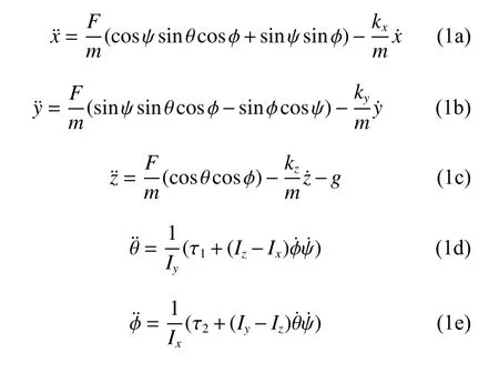
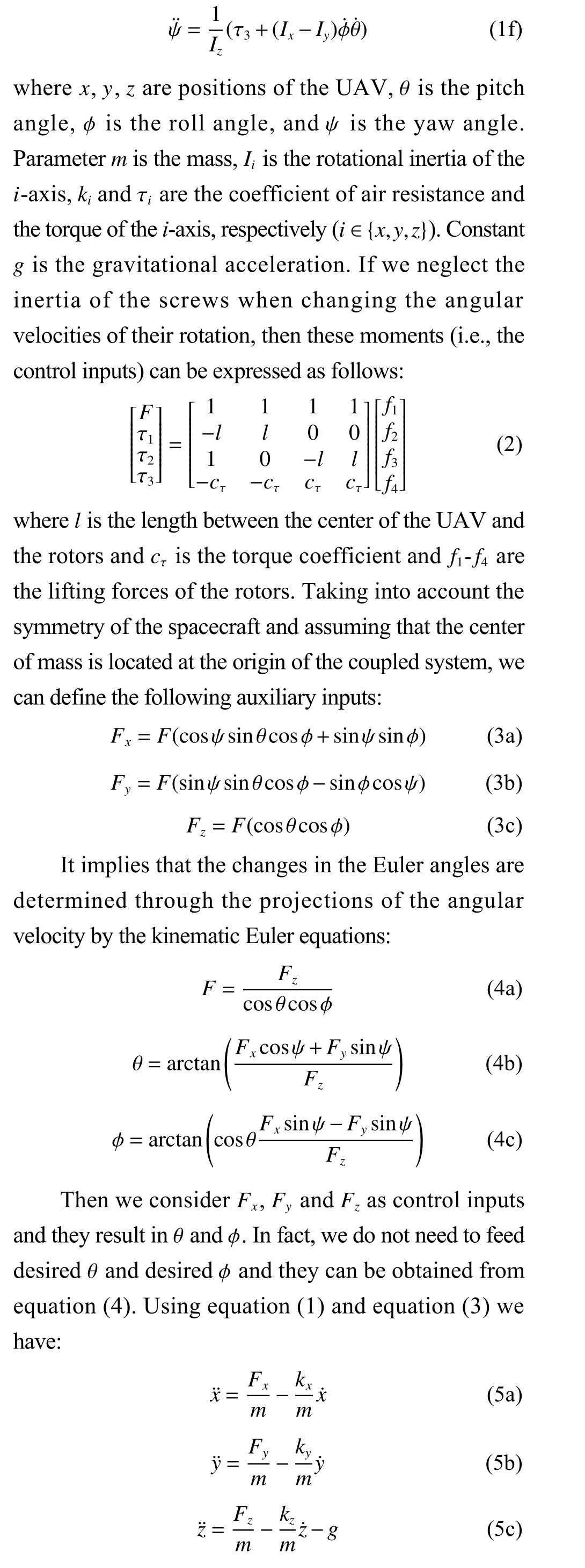
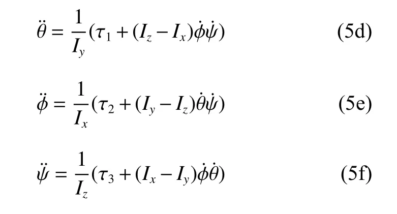
Then, the 6-DOF nonlinear dynamic model of UAV is given by (see Fig. 1):
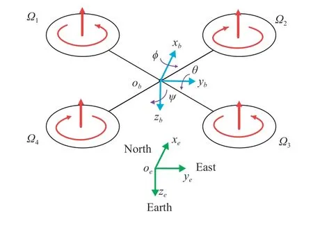
Fig.1 Free-body diagram of the quadcopter[24]
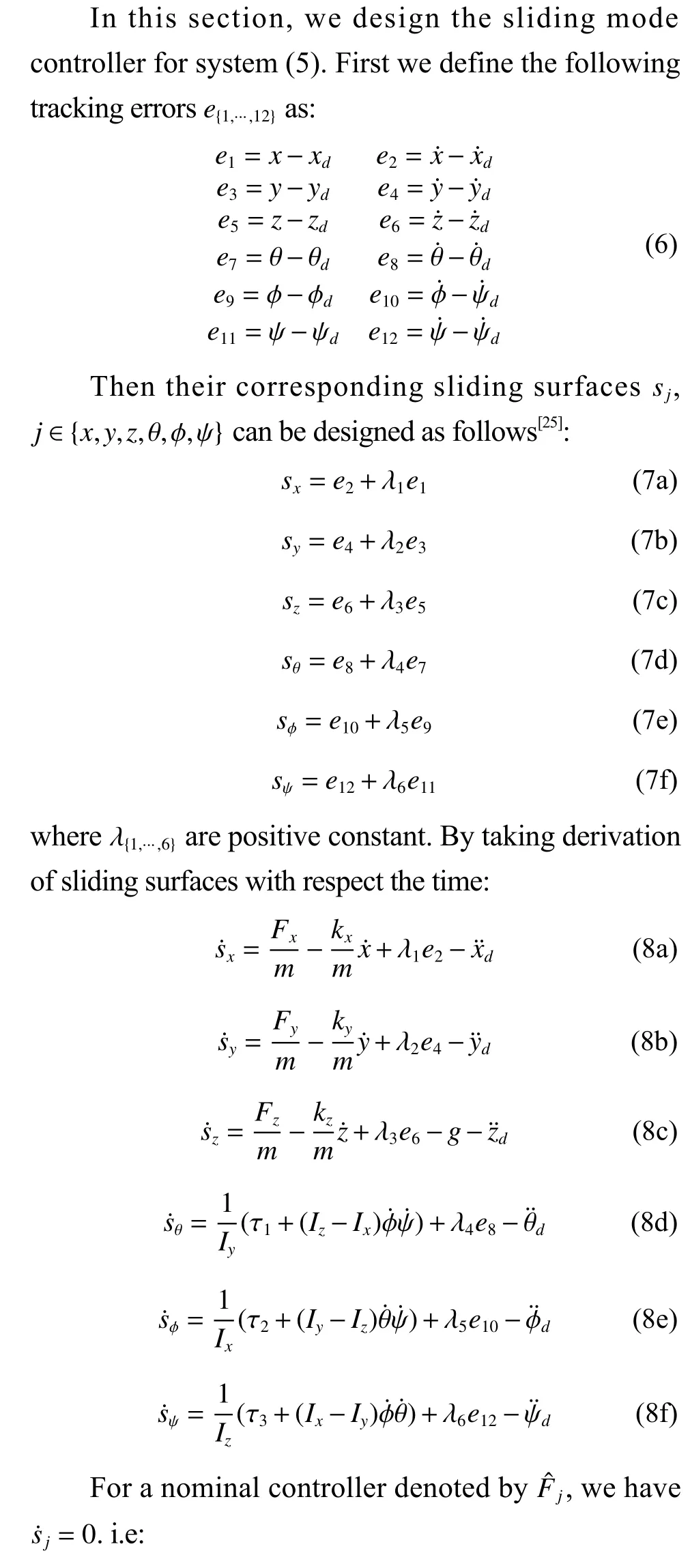
2 SMC Design for the Quadcopter UAV
3 Simulation Results
In this section, we provide simulation results for trajectory tracking of the UAV. The software environments Matlab Simulink and Universal Mechanism are used for mathematical modeling. In Matlab Simulink, it is convenient to model the dynamics by integrating the equations of motion Universal Mechanism allows. The joint use of these packages not only simplifies the implementation of the model but also allows one to obtain parallel results, the comparison of which can confirm the correctness of the proposed algorithm.
The model in Matlab Simulink (see Fig. 2) consists of four blocks: input voltages, voltage limiters, the model of motors with propellers, the model of the quadrocopter. The input signals of the model are the control voltages to the motors corresponding to control inputs (F,τ1,τ2,τ3), the output signals are flight coordinates (x,y,z) and angles ( θ,φ,ψ). The control voltages for the motors are supplied via the signal distributor and voltage limiters. For the selected motor(mode: X 2212KV980) with a linear dependence of the speed on the control voltage in the operating speed range, the input voltages are limited to values from0 V to 1 1.1 V. In the Universal Mechanism package, the quadcopter is presented as a rigid cruciform body with four motors and four propellers with 6 DOF. And the inertial characteristics are the same as those specified in the Matlab package.

Fig.2 Mathematical model of a quadrocopter in Matlab Simulink
The structure of the control system is shown in Fig. 3, where the numbers indicate: 1—given trajectory;2—corrective devices (CU) of the trajectory control subsystem; 3—coordinate converter; 4—regulator of the orientation and stabilization subsystem; 5—signal distributor; 6—voltage limiter; 7—model of the propeller group; 8—quadrocopter model.

Fig.3 Quadcopter control system diagram
For the reference trajectory, we use the following desired path:
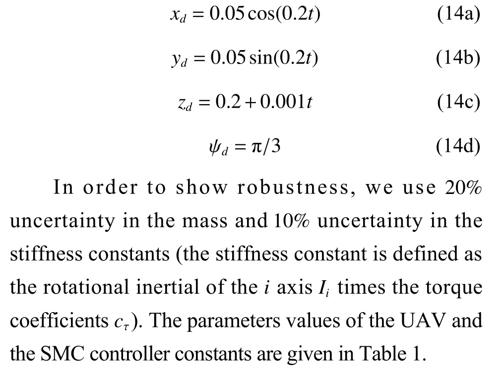
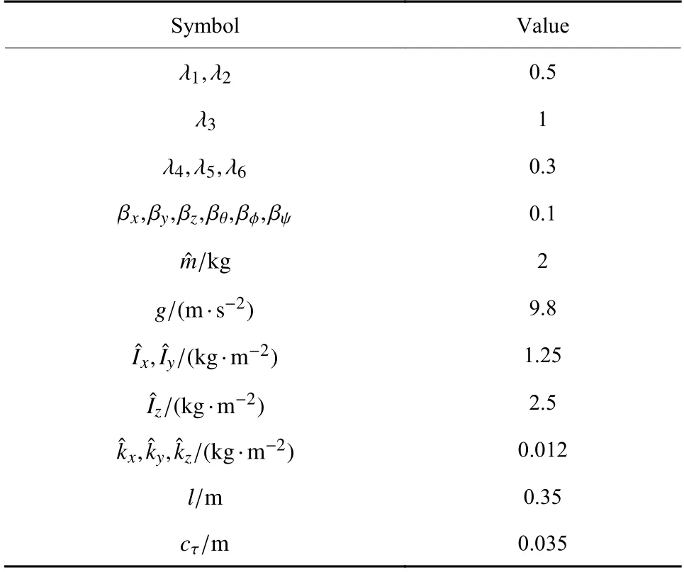
Table 1 Nominal parameters of the UAV and SMC controller
Fig. 4 shows the desired trajectories and UAV trajectories. As it can be seen, the UAV trajectories track the desired trajectories. Fig. 5 illustrates the desired path and UAV path and Fig. 6 shows the control inputs.Fig. 7 shows sliding surfacessx,sy,szandsψ. As it can be seen, all surfaces are stable and they converge to zero.Finally, Fig. 8 illustrates the tracking errors.
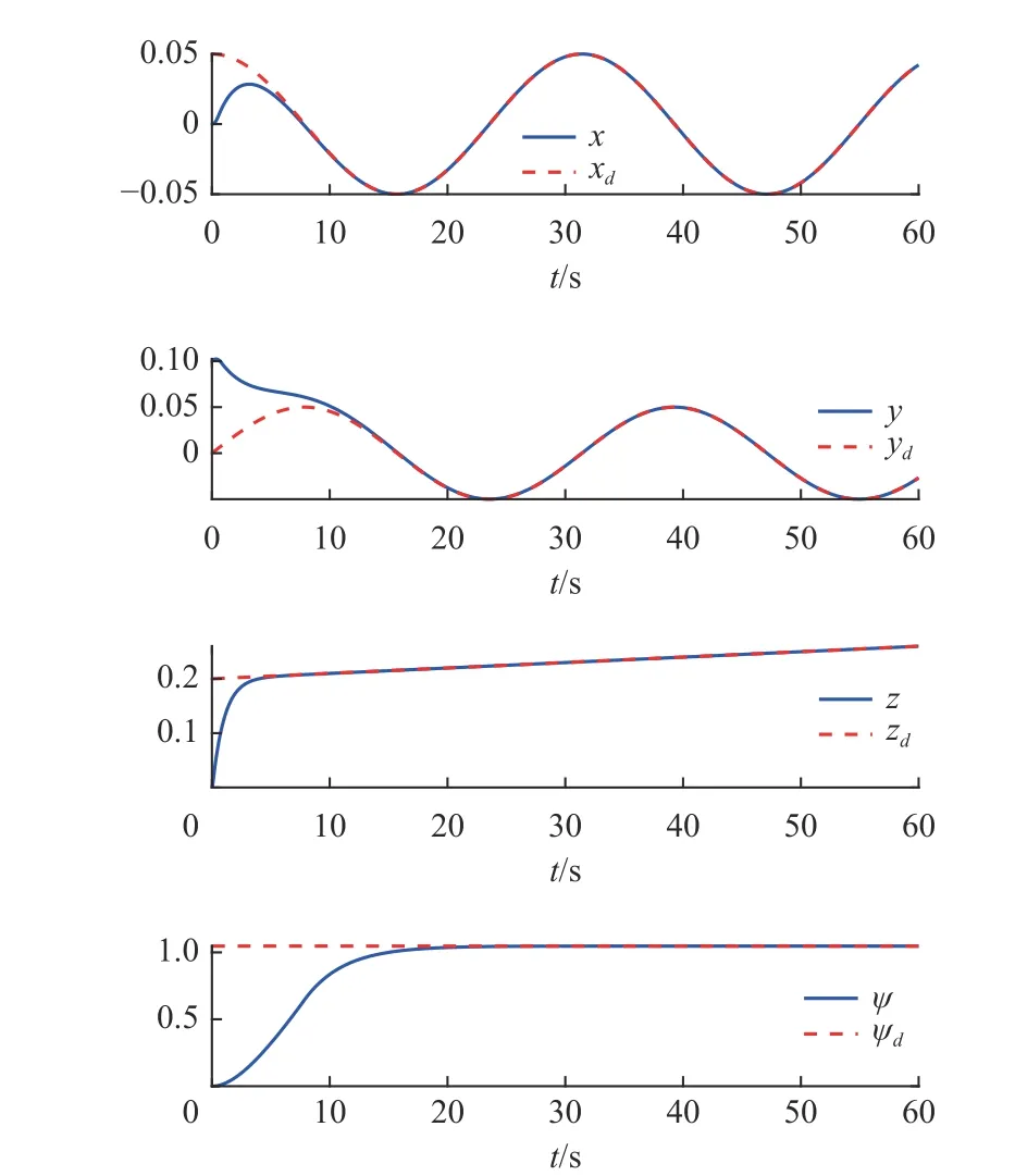
Fig.4 Desired trajectories and UAV trajectories
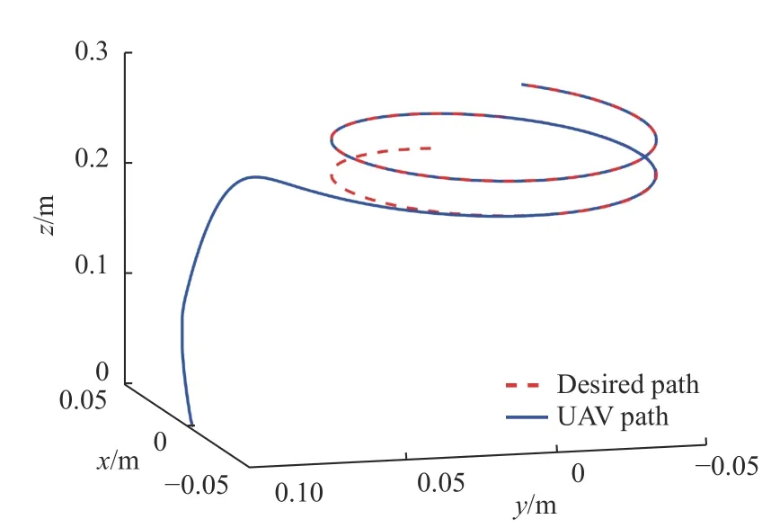
Fig.5 Desired path and UAV path
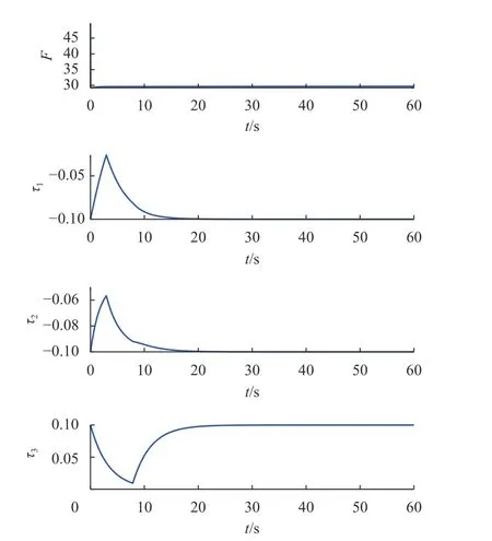
Fig.6 Control inputs F,τ1,τ2,τ3
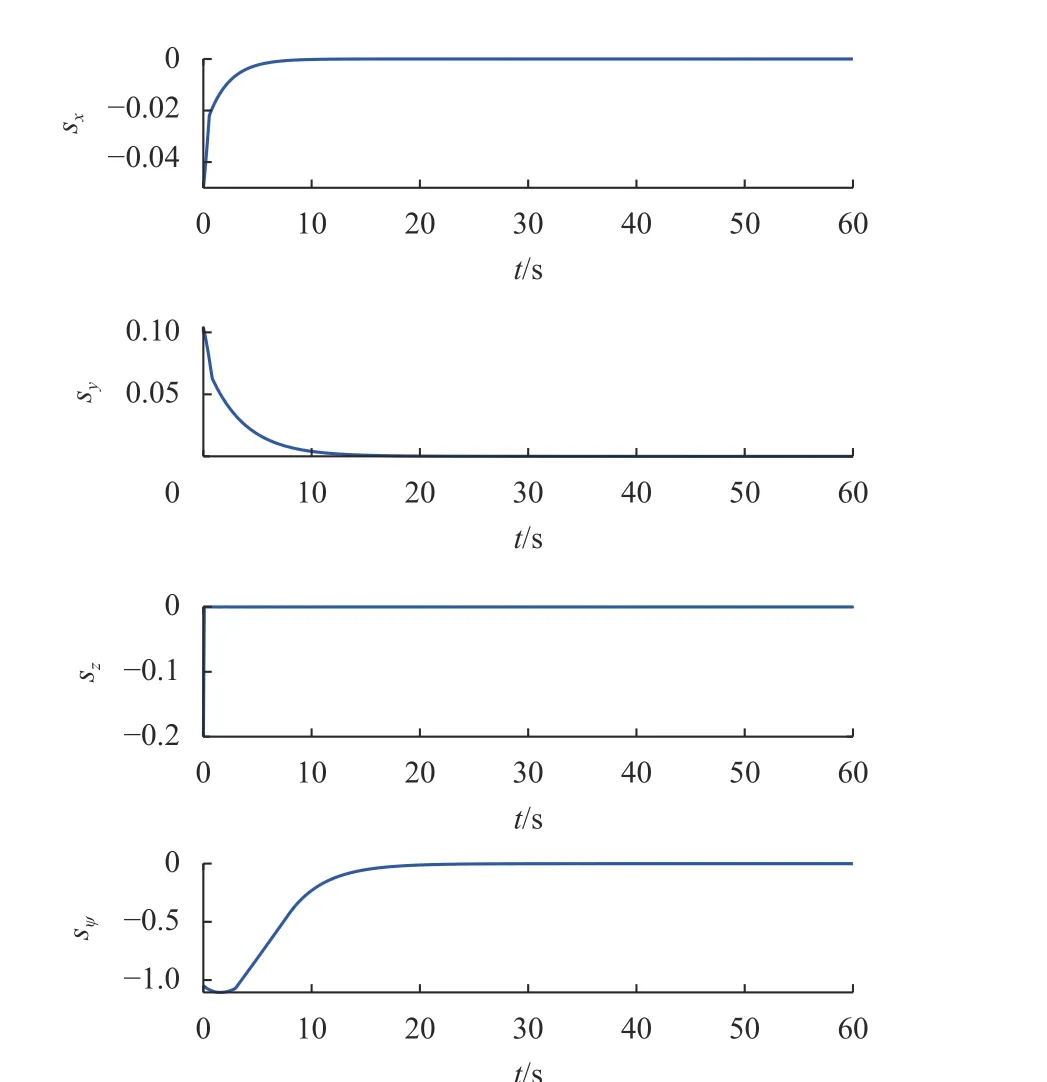
Fig.7 Sliding surfaces sx,sy,sz,sψ
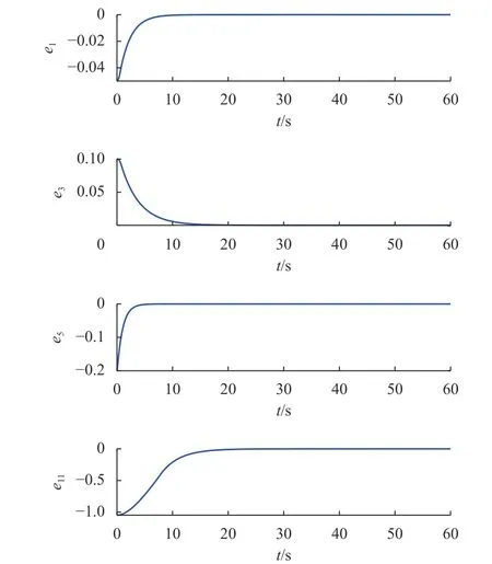
Fig.8 Tracking errors for x, y, z and ψ
4 Real Implementation
To further validate the reliability of the proposed algorithm, we use an actual quadrotor UAV for indoor flight experiments.
The detailed system configuration is described in Fig. 9. In this flight test, four VICON cameras with a capture range of 3 m×3 m×1.5 m are used. A quadrotor-type Pelican platform from AscTec(Ascending Technology) is used as a multi-rotor flying robot platform. Pelican consists of HLP (High-Level Processor) and LLP (Low-Level Processor). In the HLP,guidance and SMC control algorithms are executed based on position data such as GPS, user design code can be compiled using the SDK, and motor control signals are transferred from the compiled implementation code to the LLP. The LLP transfers IMU data and motor control signal data from the HLP to the motor drivers. The Pelican flight platform is equipped with sensors such as a gyroscope,accelerometer, geomagnetometer, GPS, and barometer.In this study, the gyroscope and accelerometer inertial data (IMU Data) are used to calculate the velocity and angular velocity information using the proposed SMC algorithm, and the multi-rotor position and altitude control information is obtained by processing VICON data. The information obtained from VICON is transmitted from the GCS (Ground Control System) to the quadrotor UAV via ZigBee wireless communication and used as input values for flight control. Each IMU,GPS, PC, UART, and motor data are communicated in real-time via GCS and ZigBee. The IMU data includes measured angular velocity and acceleration data, and the GPS includes latitude, longitude, altitude, and speed data. The PC receives signals from the remote control,and UART receives command values from the GCS input. Position and yaw information from VICON are transferred from MATLAB to the Simulink-based GCS,which classifies the data and transmits them to the vehicle. The parameter values for the real-time test flight are: total weight is 1 .63 kg, center distance from the rotor is 0.225 m , thrust efficiency is 3 .6×10−2, and drag efficiency equals to 1 .8×10−2.
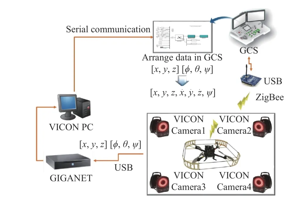
Fig.9 Experimental implementation for data workflow between GSC and quadrocopter with motion capture system
For the real experimental testing, we apply the proposed SMC algorithm to simulate a complete flight mission, including the takeoff and landing of the UAV.Fig. 10 shows the results of the results when tracking the trajectory consisting of sections: AB—takeoff;BC—uniform rectilinear motion; CD—uniform accelerated rectilinear motion; DE—uniform movement around the point ( 5,10,15) in a horizontal circle with a radius of 5 m; EF—uniform rectilinear motion;FG—uniform movement around the point ( −5,10,10) in a horizontal circle with a radius of 10 m; GH—landing.As can be seen, the results are generally satisfactory as well.
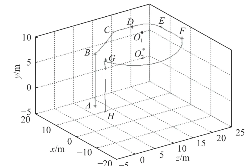
Fig.10 Full trajectory tracking mission involves takeoff and landing
As previously described, in the case of multi-rotor UAVs, which are susceptible to external environmental uncertainties, stable flight performance is required even if there are unforeseen external disturbances. Therefore,we also need to validate the robustness of the designed SMC controller. An experiment is conducted using a digital dynamometer to generate disturbances on the quadcopter from the outside. Perturbations are added in the form of impulse shocks through the dynamometer to produce the effect of sudden gusts of wind, and the disturbance forces are measured as digital data values.The perturbation experiments are performed in theXandZdirections (horizontal and vertical directions) of the vehicle, respectively.
The perturbation to theX-direction is input about 15 safter the flight, and the maximum peak of the force is set to 4.7 N. The applied perturbation results in a position error of up to 0 .45 m in theX-direction but is confirmed to return to the reference command value of 0 m within 1 s by the SMC controller. The results are shown in Fig. 11. The perturbation to theZ-direction is input at around 4 1 s. The maximum peak of the force is set to 7 .6 N . The perturbation to theZ-direction results in a height error of up to 0 .3 m, but is confirmed to return to the existing standard command value of0.7 m within 1 s. The results are shown in Fig. 12. In the case of the horizontal disturbance, an instantaneous error of 0.45 m occurs when a disturbance force of 4 .7 N is applied, and in the case of the vertical direction, an error of about 0.3 m is confirmed to have occurred at a disturbance force of 7.6 N. As shown in the experiment,the SMC controller can stabilize the quadrotor UAV again within 1 second in the presence of perturbations,showing the excellent robustness in theXandZdirections.
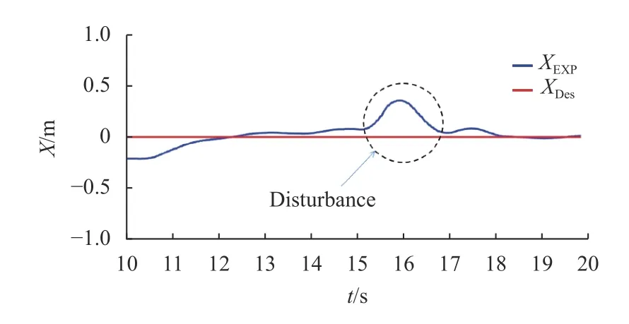
Fig.11 Test of the robustness of the proposed SMC to disturbance in X-direction
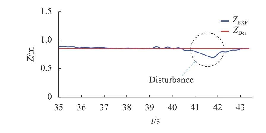
Fig.12 Test of the robustness of the proposed SMC to disturbance in Z-direction
5 Conclusion
In this work, we develop a simple sliding mode control algorithm for robust 3D trajectory tracking of a quadcopter UAV, where the controller is able to track desired paths in the presence of uncertainties. Simulation experiments with Matlab Simulink and real flight experiments are conducted to verify the performance of the proposed SMC algorithm. In particular, to verify the robustness against disturbances such as gusts of wind in an uncertain environment of quadcopter operation,disturbances are applied to the horizontal and vertical axes of the UAV and the performance is verified in terms of attitude stability. The designed SMC controller shows immediate re-stabilization of the UAV with excellent resilience in both the horizontal and vertical directions. Both simulation and real testing results show the efficiency of the SMC algorithm and the possibility of its implementation.

