Key Construction Technology of Super Large Diaphragm Wall Reinforcement Cage*
SHI Jiangchuan, LIU Weiwei, NIE Yanxia, CHENG Peichun
(1.China Construction First Group Construction & Development Co., Ltd.,Beijing 100102, China;2.Installation Engineering Co.,Ltd. of First Bureau Group of CSCEC,Beijing 102600, China)
Abstract: The longest reinforcement cage of the Shenzhen LNG Receiving Station’s underground continuous wall is 59.5m, and the total lifting weight is more than 110t. It is a super large reinforcement cage, which is extremely tough to construct and lift. The quality of reinforcement cage processing is guaranteed by adopting the mold frame and a reasonable processing procedure. Feasible technical scheme and quality and safety assurance measures are put forward from the aspects of site layout, hoisting equipment selection, hoisting point layout and hoisting process control to ensure the safe implementation of super large underground continuous wall reinforcement cage hoisting operation. Combined with the project example, the construction challenge of super large underground continuous wall reinforcement cage is solved by adopting the construction technology of integral fabrication and hoisting.
Keywords:underground engineering; diaphragm wall; reinforcement cage;formwork; hoisting; equipment selection;construction
0 Introduction
With the development of construction engineering, deep underground foundation excavations have become increasing important in the field of construction. As an effective support structure of water interception, seepage prevention and soil retaining bearing, underground diaphragm wall has been widely used. The production and hoisting of reinforcement cage is a critical link in the construction of an underground diaphragm wall, as well as a connection fraught with great construction dangers. According to past construction experience, when the length and the weight of the reinforcement cage of an underground continuous wall is too large, and the overall stiffness is poor.
In order to reduce construction risks, the construction methods such as segmented production and hoisting are often used. However, this approach has the disadvantage of being difficult to dock reinforcement cages and taking a long time to lower reinforcement cages, which may cause the collapse of underground continuous wall. Given the current construction situation of underground diaphragm wall in China, mature and reliable construction technical measures and experience are urgently needed for the overall production and hoisting of super large underground continuous wall steel cage.
The maximum depth of the ground wall of Shenzhen LNG Receiving Station is 62m, the longest length of the steel cage is 59.5m, and the total lifting weight is more than 110t. The steel cage is built as a whole and hoisted in place all at once. In light of the major and difficult points in the construction process, feasible technical measures were proposed from the aspects of site layout, overall production of steel cages, overall hoisting of steel cages, on-site quality and safety assurance, and so on, to ensure the smooth implementation of the project.
1 Project introduction
1.1 Project overview
The Shenzhen LNG Receiving Station is located in Diefu north area of Shenzhen, on the northeast side of Shenzhen Dapeng Bay, west of the S360 provincial highway. The project site, which is basically reclaimed from the sea, has a land area of about 26 hectares. In the first phase of the project, the T-1201 and T-1202 sunken gas storage tanks are installed. Both tanks have a deep circular foundation pit with an inner diameter of 100m and a dig depth of 50m. The enclosure construction adopts 1.5m thick underground continuous wall with a 54~62m wall depth. The joint form of underground continuous wall is sleeve milling joint, as shown in Fig.1.

Fig. 1 Schematic diagram of slot division
The length and width of the underground continuous wall steel cage of the project reach 59.5m and 5.6m, making it a super large steel cage. The steel cage reinforcement is extremely dense, as shown in Fig.2. The dead weight reaches 95t including the additional load weight, and the overall lifting weight exceeds 110t.

Fig. 2 Section of reinforcement cage
1.2 Analysis of the difficulties in fabricating and hoisting steel cages
1) Because the ground wall reinforcement cage is a special-shaped cage, the reinforcement arrangement is dense, various embedded parts are complex, the steel cage production accuracy requirements are high, and the steel cage is too long and overweight, ensuring the overall stiffness of the steel cage is a significant challenge.
2) The site has a lot of heavy construction machinery and equipment, and the space is limited. How to reasonably arrange the site plane and organize the hoisting walking route of reinforcement cage is of importance.
3) The steel cage is excessively lengthy and overweight, and there are many risk concerns in the lifting operation of the steel cage, making the construction problematic. The lifting scheme of the steel cage must be safe and reliable.
1.3 Site layout
The project site is rectangular in shape, with two reinforcement cage processing areas on the north and south sides of the site. Between these two areas is the steel raw material stacking and semi-finished products processing area for steel cutting, bending, wire and other operations.
To meet the walking requirements of the reinforcement cage hoisting equipment of the ground wall, a heavy road 12~14m wide is established in the outer ring of the ground wall and the north and south sides of the site. The heavy road adopts 35cm thick reinforced concrete, allowing for smooth and safe hoisting and walking of heavy equipment.
2 Reinforcement cage integral processing technology
The reinforcement cage of underground continuous wall is densely reinforced, with the main reinforcement is in the form of 3 parallel reinforcements connected by mechanical joints. If the steel cage is lifted by sections, it is difficult to complete the joint of the steel cage. In addition, the depth of underground diaphragm wall is large, and it takes a long time for the hole to butt with the reinforcement cage, resulting in the collapse of the diaphragm wall. Comprehensive consideration, the wall reinforcement cage adopts a whole one-time processing molding and a whole hoisting in place construction method.
2.1 Reinforcement cage processing mold frame
In order to meet the requirements of the precision and quality of the steel cage processing, it is necessary to produce a special-shaped mold frame based on the shape of the reinforcement cage. First, concrete is hardened in the reinforcement cage processing area to ensure the flatness and bearing capacity of the processing site. Then, depending on the size and shape of the reinforcement cage, the mold frame is then welded using the I-steel and channel steel, as shown in Fig.3. After welding, the level and steel ruler are used to examine the elevation and size of the mold frame to confirm that the length, width, angle and flatness of the mold frame fulfill the specifications.
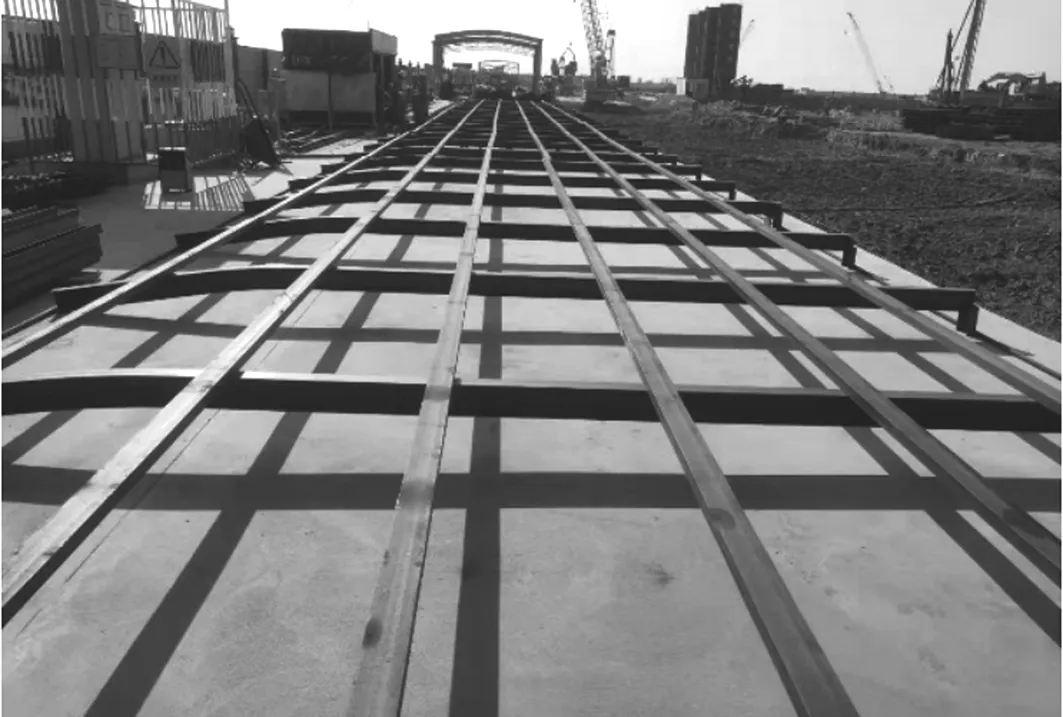
Fig. 3 Reinforcement cage mold frame
2.2 Reinforcement of steel cage
The steel cage in this project is excessively long and overweight. To strengthen the overall stiffness of the steel cage and reduce the deformation of the steel cage during the lifting process, it is required to reinforce the whole steel cage and the lifting point. In this project, 32mm steel bars are used as longitudinal truss bars and horizontal truss bars of the steel cage. Among them, five trusses of longitudinal truss bars are set in the width direction of the steel cage, with a spacing of about 1m. The horizontal truss bars are arranged every 3m along the length of the cage.
The layout of the truss bars can significantly enhance the overall stiffness of the cage. At the lifting point of the steel cage, the 25mm thickness steel plate skeleton is welded for reinforcement, and the concentrated force of the lifting point is properly dispersed to the steel cage body, as shown in Fig.4.
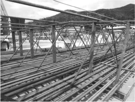
Fig. 4 Reinforcement form of steel cage
2.3 Producing process of reinforcement cages
2.3.1Production molding sequence of reinforcement cages
In order to ensure the processing quality and forming speed of reinforcement cage, the optimal processing sequence of ground wall reinforcement cage is found through analysis and practice, combining with the structural parameters of reinforcement cage. Bottom horizontal bar→bottom longitudinal bar→longitudinal truss bar→horizontal truss bar→steel plate frame at lifting point position→acoustic tube, grouting sleeve→embedded bar, shear bar→upper longitudinal bar→upper horizontal bar→horizontal sealing bar.
2.3.2Control points for reinforcement cage production
1)In the process of producing steel cages, it is necessary to arrange truss bars, tie bars, and embedded bars reasonably to ensure that enough space is left for the concrete pouring pipe to prevent it from being stuck and unable to pull out.
2)When the steel cage is placed beneath, it is necessary to use the shoulder pole to temporarily fix the steel cage to the guide wall, to complete the lifting point conversion. Therefore, the reinforcement cage processing needs to upper-planning the position and space of the carrying pole, when necessary, appropriate adjustment of the main bar spacing, to ensure that the carrying pole can be inserted smoothly.
3)The length of the steel cage hanging bar and lifting ring should be based on the design elevation of the cage top, and determined by the actual guide wall elevation, to ensure that the steel cage is installed to the correct elevation.
4)The stress at the lifting point of the reinforcement cage is more concentrated, so it should be properly strengthened to ensure full and firm welding.
5)In the production process of reinforcement cage processing, timely notify the monitoring unit to ensure the advance installation of monitoring components.
3 Reinforcement cage overall hoisting scheme
3.1 Hoisting equipment selection
The length of the ground wall reinforcement cage in this project is 59.5m, and the dead weight is 95t. The total lifting weight, including auxiliary weight such as hooks, shoulder poles and slings, is more than 110t, making a rare super-large underground continuous wall reinforcement cage in China.
In this project, the reinforcement cage hoisting adopts the construction method of double machine coordination and one-time overall hoisting, which is extremely challenging. The reasonable selection of reinforcement cage hoisting equipment is critical for the construction safety. Lifting equipment must meet the requirements of capacity, lifting height and other standards.
1) Hoisting height requirements
The maximum length of the reinforcement cage upright is 59.5m. With the 0.5m from the ground, the distance between the hook and the end of the boom is about 6m. The total height of the sling and wire rope below the hook is about 10m, then the vertical height of the lifting must be at least 76m.
2) Hoisting capacity requirements
When the reinforcement cage is in the upright state, the main crane has the maximum stress. The total lifting load is 110t, and the safety factor is 0.7, when the main crane is walking, so the lifting capacity of the main crane must be at least 157t.
According to relevant research and construction experience, the maximum force of the auxiliary crane in the process of rotating vertically in the air from flat lifting is set to be 70% lifting load, so the load to be borne by the auxiliary crane is 77t. If the safety factor of the auxiliary crane is 0.8, the lifting capacity of the auxiliary crane should reach 96.25t.
3) Crane selection
Based on the lifting capacity, hoisting height requirements and site conditions, Zoomlion ZCC5200S type 400t crawler crane is selected as the main crane, with an arm length of 84m and a turning radius of 16m. According to the crane performance parameter table, the lifting capacity is 176t>157t, and the lifting height can reach 85m>76m under this situation, all of which meet the needs of usage and have a margin.
The auxiliary crane is a XCMG XGC260 type 260t crawler crane. According to the performance parameter table, when the arm length is 51m and the working radius is 12m, the lifting capacity is 109t>96.25t, which can meet the requirements.
3.2 Layout of reinforcement cage lifting point and selection of sling
If the position to lift the reinforcement cage is not calculated accurately, it will result in substantial deflection deformation, causing the weld to cracks, the overall structure to break, and the lifting to be impossible. Therefore, determining the lifting point position is an important step in the lifting process. According to the law of moment balance, when the positive and negative moments are equal, the bending moment deformation is the minimum, as shown in Fig.5.

Fig. 5 Schematic diagram of reinforcement cage bending moment
As a result, selectingB,C,D,E,F,G, a total of six rows of hoisting points, has the smallest bending moment while hoisting. Practically, the pointsB,C, andDare the main hoisting positions, andE,F,Gare the auxiliary hoisting positions.
Depending on the width of the reinforcement cage, there are four lifting points in each row horizontally, for a total of twenty-four lifting points. Based on the structure of the reinforcement cage, the hoisting position is appropriately adjusted. Both the main and auxiliary cranes have two sets of pulleys and a total of twelve lifting points, as shown in Fig.6 and Fig.7.

Fig. 6 Layout of reinforcement cage hoisting rigging

Fig. 7 Plane distribution of reinforcement cage lifting points
According to the distribution of lifting points and the stress state of the reinforcement cage, the most adverse stress condition of the lifting sling is calculated, and the sling selection is determined based on the stress condition of wire rope and pulley, as shown in Table 1.

Table 1 Details of stress and selection of reinforcement cage hoisting rigging
3.3 Reinforcement cage hoisting process
The general procedure of hoisting the reinforcement cage is double-machine in place→double-machine horizontal lift test hoisting→double-machine cooperates to turn over in the air→reinforcement cage vertical→main crane walks into place→reinforcement cage enters the groove.
1) Crane in position
The two crawler cranes are placed at the predetermined positions according to the station layout plan, and checked whether the ground flatness and ground endurance meet the requirements, as shown in Fig.8.
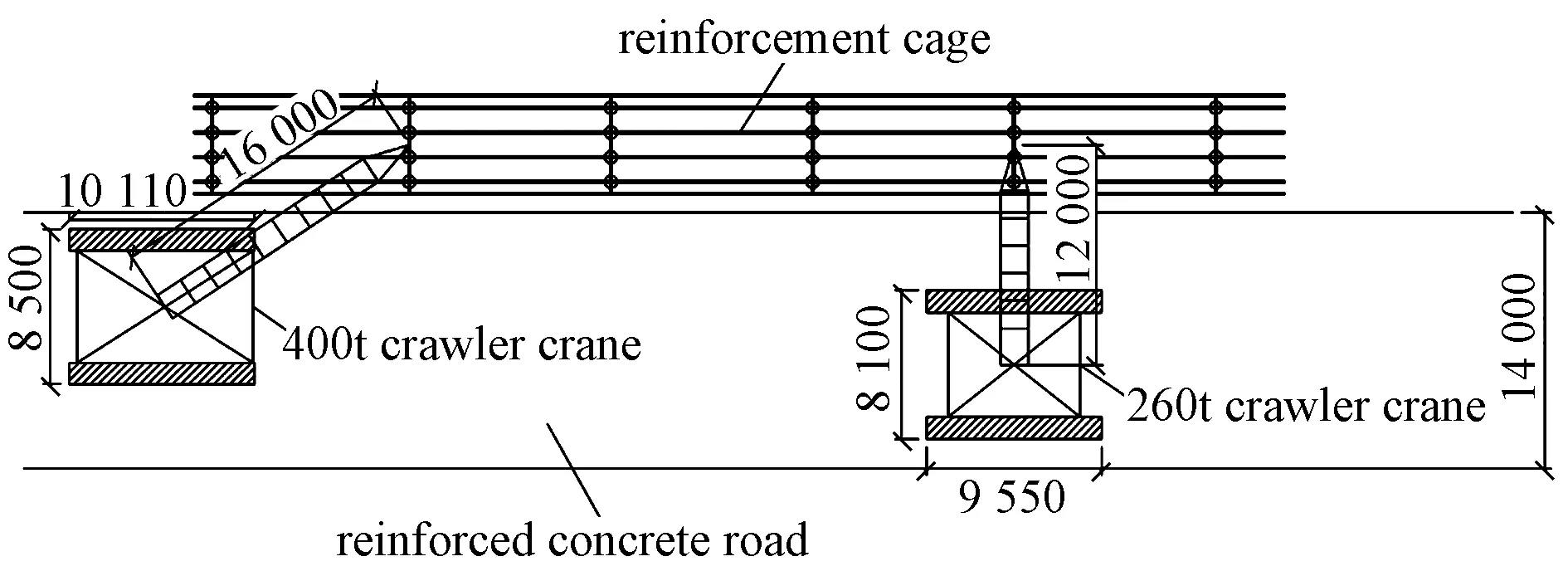
Fig. 8 Hoisting station map of crane
To prevent the reinforcement cage from shaking during lifting, adjust the operating range and angle of the crawler crane to ensure that the center of the hook coincides with the reinforcement cage’s center of gravity.
2) Horizontal lift test
To verify that the crane, hoisting rigging and steel cage stiffness of the steel cage hoisting scheme can meet the design requirements and ensure the safety during the hoisting process, the steel cage is tested before the formal hoisting. The two crawler cranes work together to lift the steel cage by 50cm and hold it still for 10min. Examine the steel cage for deformation and welding, as well as the working status of the crane.
If there was no abnormal situation, the next operation could be continued. Otherwise, the steel cage should be put back on the platform to strengthen or optimize the position of the lifting point.
3) Turn upright in the air
The main crane gradually lifts the hook, the reinforcement cage is inclined in the air, the auxiliary crane and the main crane gradually close in on each other, and the reinforcement cage is gradually adjusted to a vertical position.
4) Main crane walking
The auxiliary crane is unhooked and moved away from the reinforcement cage once it is vertical, and the 400t main crane is instructed to hoist the reinforcement cage and walk to the groove section. The crane should be kept stable during the walking process, and a traction rope should be placed on the reinforcement cage to reduce the shaking of the steel cage.
5) Reinforcement cage lowering and lifting point conversion
After the reinforcement cage is inserted in the groove, the three rows of suspension points of the auxiliary crane are gradually released, and the lifting point conversion is gradually completed when the main lifting point is released. The process is as follows.
As shown in Fig.9, when the reinforcement cage is lowered to the shackle 4, insert the side pole into the reserved hole of the reinforcement cage to temporarily fixed on the guide wall, and remove the shackle 4 of the third row of lifting points from the cage body. The hook of the main crane is lowered slowly, the pulley 2 is removed and the wire rope end is connected with the shackle 4. Then the hook is lifted to tighten the connected wire rope, and the pole is pulled out to continue lowering the reinforcement cage.
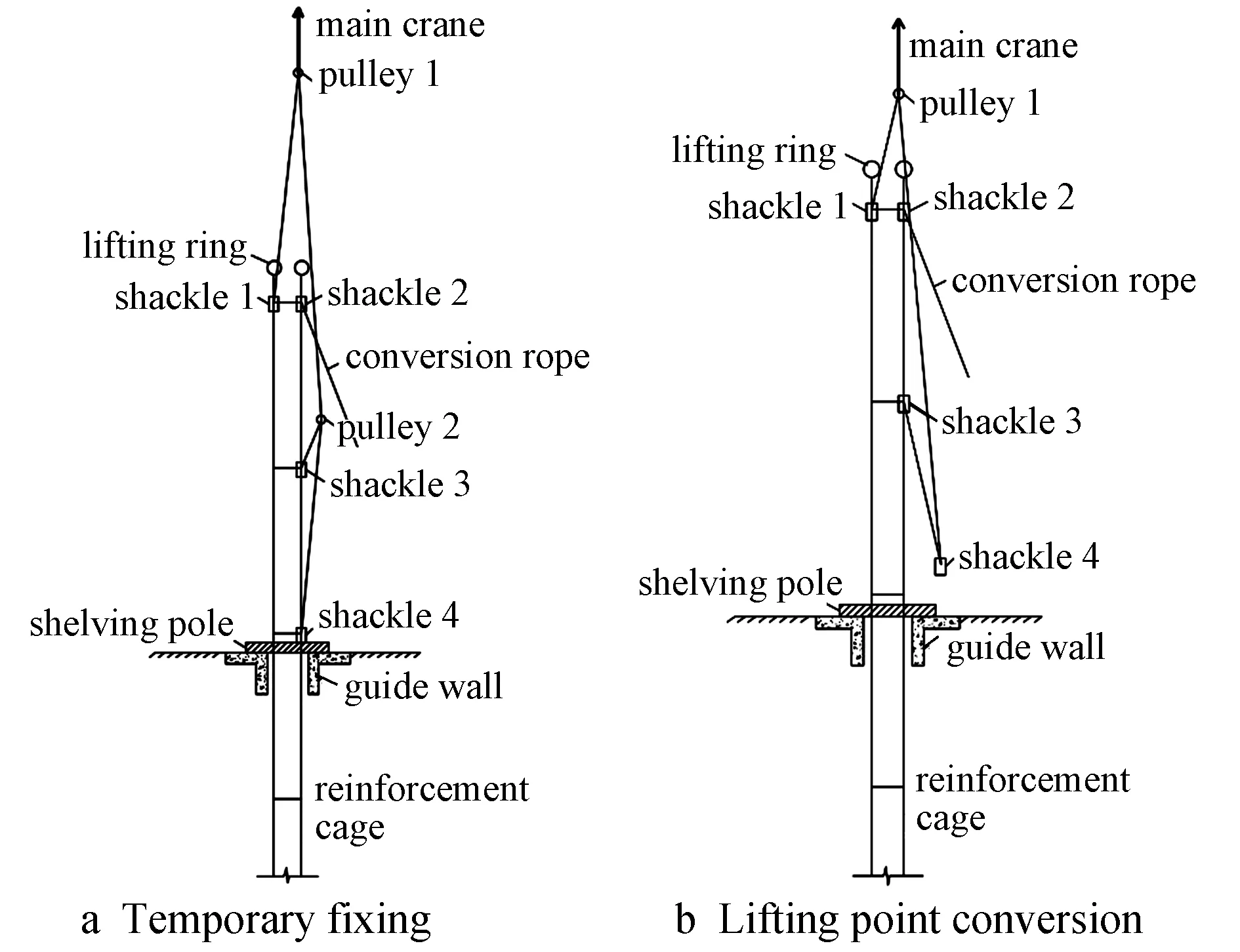
Fig. 9 Transformation process I of steel cage lifting point
As shown in Fig.10, continue to lower the reinforcement cage to the shackle 3, then insert the shelving pole into the reserved hole of the reinforcement cage to fix it to the guide wall again. Remove the shackle 3 of the second row of lifting points from the cage body and reserve it in advance. The rope ends of the conversion rope are connected, and the hook is hooked again to tighten the connected wire rope. The pole is pulled out to continue lowering the reinforcement cage.

Fig. 10 Transformation process II of steel cage lifting point
As shown in Fig.11, continue to lower the reinforcement cage to the shackle 2, insert the shelving pole into the reserved hole of the steel cage again, and convert the shackles 1 and 2 to the lifting ring at the top of the reinforcement cage, then pull out the shelving pole and continue to lower the reinforcement cage to the design elevation. By inserting the shelving pole into the lifting ring to fix it, and the reinforcement cage lowering is completed.
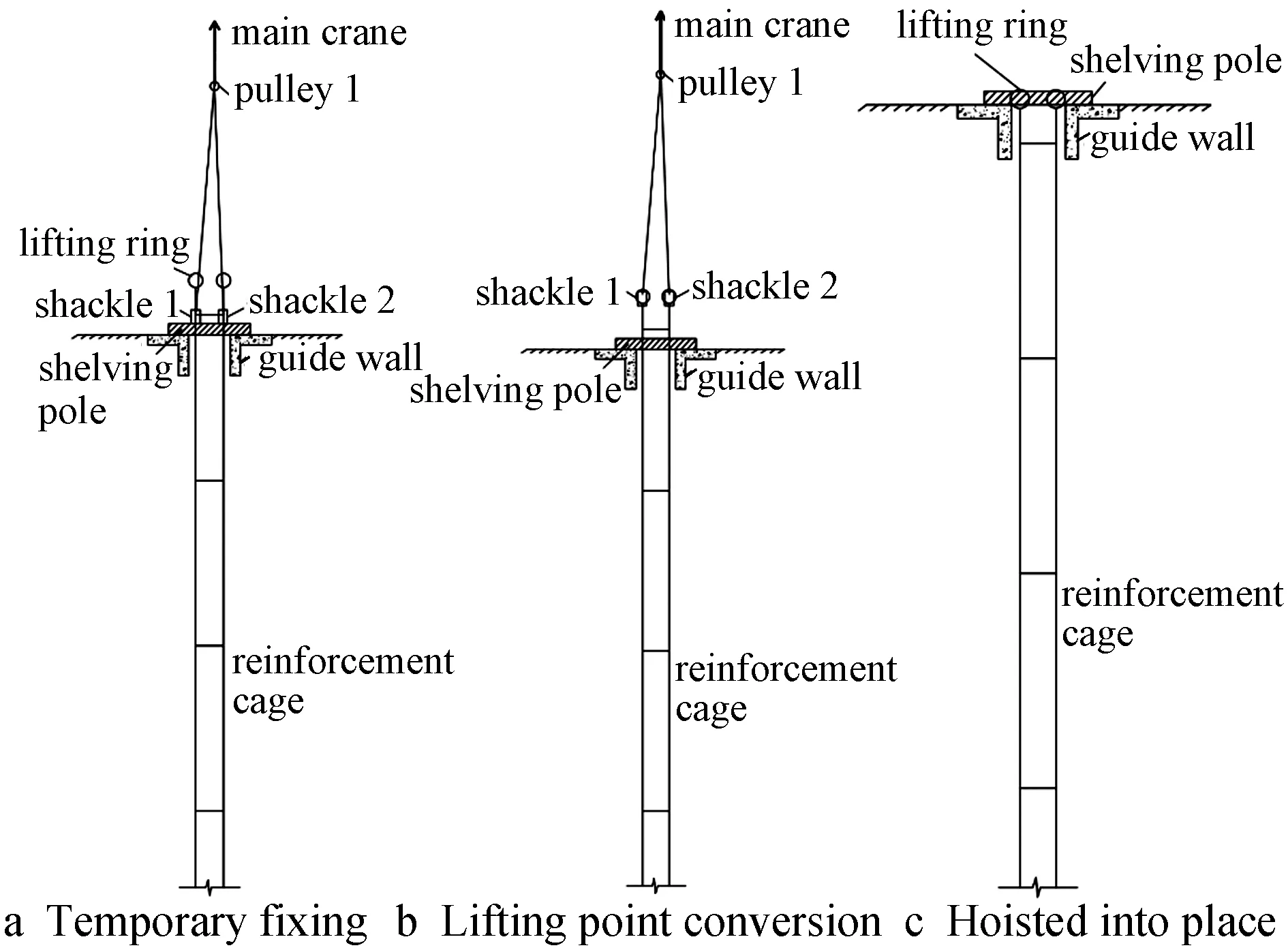
Fig. 11 Transformation process III of steel cage lifting point
4 Quality and safety management
1) Before the reinforcement cage hoisting, the wall grooving detection should be completed. The perpendicularity, width, thickness and depth of the grooving must meet the design requirements to prevent the reinforcement cage from rubbing the groove wall.
2) After the reinforcement cage has been processed, all parties should be notified for inspection and acceptance, and the size of the reinforcement cage, the welding connection, and the reinforcement of the lifting point should be checked whether they meet the design requirements. In addition, it is necessary to focus on cleaning and checking whether there are any debris such as steel bars on the cage body to prevent objects falling from high altitudes during the hoisting process.
3) Crane station position and walking route should be clear before hoisting operation. Hoisting and commanding personnel must have a special operation qualification certificate. The steel cage hoisting process should be unified under the command and management of special signal commander, and other irrelevant personnel should be evacuated from the warning area of hoisting operation.
5 Conclusion
1) The underground continuous wall reinforcement cage of this project is a super large reinforcement cage, which is extremely difficult to construct and lift. In view of the difficulties encountered throughout the construction process, this paper presents practical solutions from the site layout, reinforcement cage production, reinforcement cage hoisting and other aspects of the construction process that meet the requirements of the site construction.
2) By making the formwork in advance, the accuracy of the manufacturing of the underground diaphragm wall reinforcement cage is ensured. For the super large reinforcement cage, the reinforcement form of the truss bar combined with the steel plate frame is proposed to ensure the overall rigidity of the super long and overweight steel cage. The optimal processing sequence and production points of the reinforcement cage are obtained, which improves the speed and quality of the processing and forming of the reinforcement cage.
3) This project adopts the construction method of a one-time overall hoisting of the 59.5m long reinforcement cage, and the construction difficulty is rare in China. To ensure a smooth hoisting construction, reasonable calculation are used to determine hoisting equipment, sling selection, hoisting point setting, and conversion.
4) The key construction control points during the hoisting operation of the reinforcement cage are identified, and the technical, quality and safety measures are clarified to ensure the smooth implementation of the hoisting operation of the reinforcement cage.

