Omnidirectional Antenna Diversity System for High-Speed Onboard Communication
Yongjian Zhang, Yue Li,*, Weiquan Zhang, Zhijun Zhang, Zhenghe Feng
a Department of Electronic Engineering, Tsinghua University, Beijing 100084, China
b Beijing National Research Center for Information Science and Technology, Tsinghua University, Beijing 100084, China
Keywords:Antenna diversity system Aerodynamics Electromagnetics Omnidirectional radiation High-speed onboard communication
ABSTRACT In this article, an omnidirectional dual-polarized antenna with synergetic electromagnetic and aerodynamic properties is propounded for high-speed diversity systems. The propounded antenna comprises a probe-fed cavity for horizontally polarized radiation and a microstrip-fed slot for vertical polarization.Double-layer metasurfaces are properly designed as artificial magnetic conductor boundaries with direct metal-mountable onboard installation and compact sizes.An attached wedge-shaped block is utilized for windage reduction in hydrodynamics. The propounded antenna is fabricated for design verification, and the experimental results agree well with the simulated ones. For vertical polarization, the operating bandwidth is in the range of 2.37–2.55 GHz, and the realized gain variation in the azimuthal radiation pattern is 3.67 decibels (dB). While an impedance bandwidth in the range of 2.45–2.47 GHz and a gain variation of 3.71 dB are also achieved for horizontal polarization. A port isolation more than 33 dB is obtained in a compact volume of 0.247λ0 × 0.345λ0 × 0.074λ0, where λ0 represents the wavelength in vacuum at the center frequency,wherein the wedge-shaped block is included.The propounded diversity antenna has electromagnetic and aerodynamic merits,and exhibits an excellent potential for high-speed onboard communication.
1. Introduction
Dual-polarized antennas transmit and receive electromagnetic waves in two orthogonal polarizations, and are of significant interest in multiple-input multiple-output systems[1–6]owing to the remarkable merits of channel capacity enhancement and the alleviation of polarization mismatch. Conversely, omnidirectional antennas are usually achieved for full coverage in the azimuthal plane[7–12],thus improving the reliability of communication links.Based on these requirements,omnidirectional dual-polarized(ODP)antennas have been extensively studied in recent years. There are two critical indices for ODP antennas,namely,polarization isolation and radiation patterns (angle distribution of radiated electromagnetic waves in the far field). Thus, the radiation elements of ODP antennas should be selected and arranged appropriately.A crossed bowtie dipole and an inverted-cone monopole are fabricated perpendicularly for horizontal and vertical polarizations in Ref. [13].In Ref. [14], an ODP antenna is designed with the combination of an optimized monopole and a circular loop. By locating an asymmetric bicone and six printed dipoles together, another ODP antenna is propounded in Ref. [15]. Furthermore, a dielectric resonator antenna is designed and used as the ODP antenna that operates at different resonant modes in Refs.[16,17].
Furthermore, a low-antenna windage requirement should be satisfied with high-speed onboard communication [18,19]. For example, the traffic collision avoidance system has requirements for ①360°signal coverage for all-round detection in the azimuthal plane,and ②multiple electromagnetic polarization components in cases of polarization mismatch. The ODP antennas on fighter fuselage demand low-windage and compact sizes to decrease air resistance and reduce energy consumption.A low-height,wearable ODP antenna array for on-body communication is propounded with L-shaped slots and a top-loaded patch in Ref. [20]. In Ref.[21], a cavity-backed slot and a folded slot are etched properly on a slender cavity with high-port isolation and azimuthally omnidirectional radiation patterns. For further volume reduction,the design in Ref. [22] adopts an open-ended thin cavity as the omnidirectional horizontal-polarized radiation element and then uses a folded slot with the azimuthally omnidirectional radiation for vertical polarization. However, the compact antennas propounded in Refs. [20–22] should be located at least one quarter wavelength above the metal ground—that acts as a perfect electric conductor boundary—thus causing an increased overall system volume. Furthermore, in recent research, the designs of propounded compact antennas are inspired by the concept of metasurfaces [23–25], but not used in the design of ODP antennas.
In this article, we propound a saber-like ODP antenna with dual-layer metasurfaces that has excellent performances of electromagnetics and aerodynamics.Fig.1 displays the application scenario of the antenna mounted on a fighter in high-speed onboard systems. In the propounded antenna, the compact, dual-layer metasurfaces are modified and inserted inside the thin cavity as artificial magnetic conductor (AMC) boundaries. Thus, the propounded antenna can be mounted directly on the metallic surface for compact system dimensions. For further windage reduction, a wedge-shaped block is attached to the cavity based on hydromechanics analysis. As a result, the propounded ODP antenna is designed by combining a thin probe-fed cavity, a microstrip-fed folded slot, two dual-layer metasurfaces, and a wedge-shaped block. Its dimensions are 30 mm × 42 mm × 9 mm (i.e., 0.247λ0×0.345λ0×0.074λ0, where λ0represents the wavelength in vacuum at the center frequency).The windage coefficient of the antenna is 29.6% lower than the conventional design without the wedge block.The port isolation is higher than 33 decibels(dB),and is suitable for the practical polarization diversity systems.The measured gain variations in azimuthal radiation patterns are both lower than 3.71 dB for dual-polarization cases.
2. Theory and measurements
2.1. Antenna design
The configuration of the propounded ODP antenna is depicted in Fig. 2.It consists of a saber-like cavity and a folded slot for horizontal and vertical polarizations. As displayed in Fig. 2(a), the metal layer thickness of the cavity is t =1.0 mm, and the cavity is open-ended with a wedge-shaped block(εr=1,where εrrepresents the relative permittivity)on one side,and short-ended on the other five sides. The exploded view is depicted in Fig. 2(b). Two duallayer metasurfaces are inserted inside the cavity as AMC boundaries. When the radio-frequency signal is fed through port 1, the field of the cavity along the Z-axis operates at the zeroth-order mode (i.e., uniform field distribution) for horizontally polarized radiation with the azimuthally omnidirectional pattern. A vertical-polarized slot is carved on the cavity and operates at the first-order mode (half-sinusoidal field distribution with the maximum in the middle and the minimum at the ends)when the signal is fed by a 50Ω microstrip line through port 2.F4BM265 dielectrics(εr=2.65,tanδ=0.002,where δ represents the dielectric loss angle)are used in the propounded antenna. The propounded antenna is modelled and numerically studied in ANSYS Electronics Desktop 18.0 (ANSYS, USA). Table 1 lists the detailed parameters.
2.2. AMC design
As shown in Fig. 3(a), a regular cavity is designed as antenna A with two of its sides being open-ended(blue-dotted lines),and one side set as a radiation aperture(green-dotted line).The other three sides are metal boundaries.Based on the resonant theory of cavity,the resonant frequency f is calculated by the formula as follows:
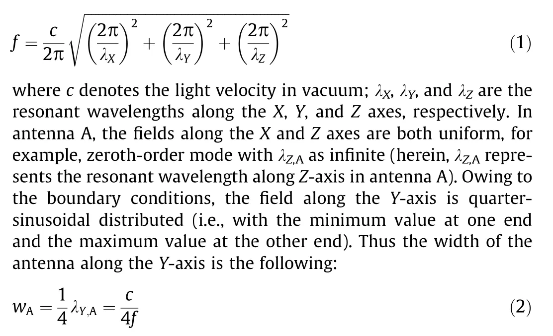
where wArepresents the length of antenna A and λY,Adenotes the resonant wavelength along Y-axis in antenna A. The height of the antenna A (hA) can take any value owing to the zeroth-order mode along the Z-axis. In this case we assume that it is equal to c/(4f).When the signal is fed through the probe,antenna A achieves a uniform field distribution on the radiation aperture. The equivalent magnetic current (black-dotted arrow) along the Z-axis realizes an azimuthally omnidirectional radiation pattern. However, this antenna has to be located at least a quarter wavelength above the metal fuselage.
To place the antenna directly on the metal surface,antenna B is propounded,as shown in Fig.3(b).Two metal sides are adopted as the short-ended boundaries (red-dotted lines) instead, thus leading to the metal fuselage’s direct installation. The field distributions are still uniform along the X-axis, quarter-sinusoidal along the Y-axis, but half-sinusoidal along the Z-axis. Therefore, the dimensions of this antenna are the following:
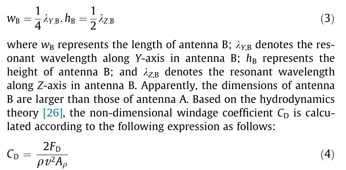
where FDrepresents the windage force,ρ is the gas density,v is the gas velocity as it flows past the object,and Aρ is the cross-sectional area of the object towards the oncoming flow stream. When the antenna shape and gas flow are fixed, the windage coefficient is constant.Thus,the cross-sectional area of the antenna impacts proportionally on the windage force. Therefore, antenna B has a larger windage force than antenna A.
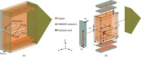
Fig.2. Geometric configuration of the propounded antenna.(a)Perspective view;(b)exploded view.t:the metal layer thickness of the cavity;w1:the width of the microstrip line;w2:the width of the horizontal slot;w3:the thickness of the dielectric;l1:the length of the cavity;l2:the height of the cavity;l3:the width of the cavity;l4:the length of the bend part of the horizontal slot;l5:the height of the probe;l6:the distance between the probe and the block;l7:the length of the microstrip line;d:the diameter of the probe.
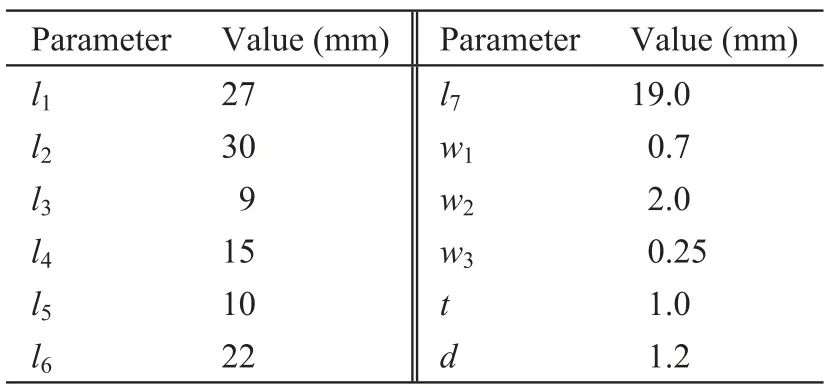
Table 1 Detailed parameters of the propounded antenna.
To reduce the windage force, antenna C is designed in Fig. 3(c).Two identical metasurfaces are inserted inside the cavity as AMC boundaries. Although the upper and lower sides of the cavity are also short-ended, this antenna operates at the zeroth-order mode along the Z-axis owing to the AMC boundary conditions. Hence,antenna C has a small windage force and the same size equal to that of antenna A (i.e., hC= hAand wC= wA, where hCrepresents the height of antenna C and wCrepresents the length of antenna C). Regarding the cost, the metasurfaces inserted into antenna C introduce a loss value of 37.4% compared with antenna A.Fig. 3(d) depicts the detailed configuration of the metasurface which is composed of staggered dual-layer patches and duallayer substrates. Based on the equivalent circuit analysis [27,28],the metasurface structure is adopted in the cavity antenna as the AMC boundary.To insert the metasurface inside such a thin cavity,the metasurface is miniaturized and optimized to the desired frequency. By the collaborative optimization of metasurface and cavity, only three unit cells are utilized as the AMC boundaries in the propounded antenna. As shown in Figs. 3(d)–(f), the parameters are labeled as the unit patch width d1=7.75 mm,the adjacent patches gap d2= 1.25 mm, the distance between double patch layers h1= 0.25 mm, and the thickness of the second substrate layer h2= 3 mm. Finally, three unit cells are inserted inside the cavity and shown as the dotted-line part in Fig. 3(d).
2.3. Dual-polarization configuration
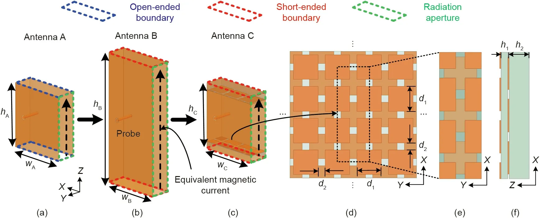
Fig. 3. Evolution of the propounded antenna for horizontal polarization. (a–c) Several antennas with different boundaries at 2.465 GHz; (d) top view of the whole metasurface;(e)top view of the metasurface used in the propounded antenna;(f)side view of the metasurface used in the propounded antenna.wA:the length of antenna A;wB:the length of antenna B;wC:the length of antenna C;hA:the height of antenna A;hB:the height of antenna B;hC:the height of antenna C;d1:the unit patch width;d2:the adjacent patches gap; h1: the distance between double patch layers; h2: the thickness of the second substrate layer.
In the design, two polarizations with similar omnidirectional radiation patterns are required. Based on the horizontal-polarized cavity antenna,a vertically polarized slot is carved on the cavity for azimuthally omnidirectional radiation and acceptable impedance matching. The entire length of the folded slot is l3+ 2l4= 33 mm(i.e., approximately λ0/2). By optimizing the length of the feeding microstrip line, the vertically polarized slot is properly matched and operates at its first-order mode. Fig. 4 illustrates the surface current distributions on the sidewalls of the cavity for two orthogonal polarizations. As depicted in Fig. 4(b), when the cavity is fed through port 1, it is observed that the surface currents are in the same direction on side 1,side 2,and side 3.Thus,the main current density (JH) is in the horizontal direction and flows parallel with the radiating slot.As port 2 is fed,the currents concentrate on both edges of the horizontal slot,as plotted in Fig.4(c).The main current density (JV) is in the vertical direction and perpendicular to the radiating slot.As a result,the total current distribution in the horizontal polarization is orthogonal with that in the vertical polarization (i.e., the integral of two current distributions is relatively small), thus indicating high-port isolation between the two ports.The isolation can be validated by the experimental transmission coefficient. That is to say, the energy fed through port 1 is with a smaller leakage to port 2.Therefore,high port isolation is obtained in the compact structure.
3. Results
A prototype of the propounded ODP antenna with a wedgeshaped block is built and measured, as depicted in Fig. 5. Two dual-layer metasurfaces are inserted inside the cavity and stuck on the lower and upper sides of the cavity,respectively.The folded slot is fed through a subminiature version A connector, which is welded with the microstrip line. The thin cavity is excited by a 50Ω coaxial cable, with the inner conductor connecting to the probe and outer conductor soldering to the cavity surface. The wedge-shaped block is hollow and printed in three-dimension using the polylactic acid. Hence, the relative permittivity of the block can be equivalently regarded as εr= 1.The impedance property of the propounded antenna is tested by the N9917A vector network analyzer (Keysight Technologies, USA), and the radiated property is measured in the microwave anechoic chamber.
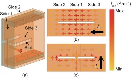
Fig.4. Surface current distributions on the cavity sidewalls.(a)Perspective view of the propounded antenna. Expanded view of the antenna and surface current distributions for dual-polarization cases:(b)horizontal polarization and(c)vertical polarization. JH: the main current density in the horizontal polarization; JV: the main current density in the vertical polarization; Jsurf: the surface current distribution; Max: the maximum value of the surface current amplitude; Min:the minimum value of the surface current amplitude.
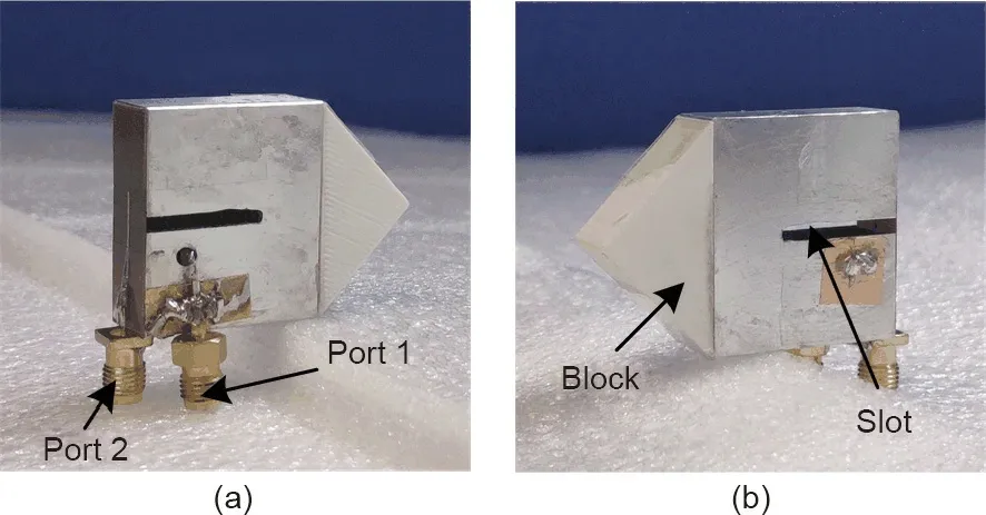
Fig. 5. Photographs of the propounded ODP antenna: (a) front and (b) rear views.
Fig. 6(a) depicts the scattering (S) parameters of the propounded antenna. The measured -10 dB impedance bandwidths|S11| and |S22| are 2.45–2.47 GHz and 2.37–2.55, respectively(|SMN| represents the received signal level from port M when the signal is transmitted through port N,and the operating impedance bandwidth is usually defined as the frequency band with a reflection coefficient, i.e., |SNN|, less than -10 dB [7–9]). The bandwidth for horizontal polarization is narrow owing to the high-qualityfactor cavity with the inserted metasurfaces. This narrow bandwidth problem can be alleviated by increasing the volume (e.g.,increasing the value of l2). The measured and simulated |S21| are both lower than -33 dB, thus implying that the port isolation is suitable for dual-polarized systems [4,5]. Fig. 6(b) illustrates the simulated and measured gains and total efficiencies of the propounded antenna. For horizontal polarization fed through port 1,the measured gain varied from 0.7 to 0.84 dBi (herein, dBi represents the gain relative to an isotropic antenna)in the desired band of 2.45–2.47 GHz, and agreed well with the simulated results.When excited through port 2 for vertically polarized radiation,the measured gain was 2.18–2.25 dBi with high total efficiency.
The normalized patterns of the propounded antenna for dual polarizations at 2.465 GHz are depicted in Fig. 7, where Eφand Eθrepresent the φ and θ components of the electric fields, respectively. Here, φ is the azimuth angle relative to the X-axis in the X-Y plane, and θ is the elevated angle relative to the Z-axis. As shown in Fig.7(a),the co-polarization(desired polarization)radiation patterns are omnidirectional in the X-Y plane when port 1 is excited.The realized gain variation in the azimuthal radiation pattern(measured results)is 3.71 dB,whereby the gain variation represents the difference between the maximum and minimum values of the gains in a radiation pattern. Fig. 7(c) illustrates the normalized patterns in the X-Y plane for vertically polarized radiation excited through port 2.The measured realized gain variation in the azimuthal plane is 3.67 dB.The cross-polarization(undesired orthogonal polarization) levels are all lower than -10 dB in the measured results. The measured vertically polarized realized gain and total efficiency are 2.25 dBi and 88.6%, and agree well with the simulated results. The measured gain and total efficiency are 0.84 dBi and 58.3% for horizontal polarization with the lossy metasurfaces.
The propounded antenna with the wedge-shaped block is studied in a commercial software ANSYS ICEM CFD 16.1 (ANSYS,USA).Table 2 lists the property comparisons between the propounded ODP antenna and other existing designs. Compared with previous designs,the propounded antenna has competitive electromagnetic characteristics, but a smaller cross-sectional area. Moreover, the windage coefficient, an essential index in high-speed communications, reduces by 29.6% by adopting the wedge-shaped block.
4. Discussion
4.1. Parametric analysis for electromagnetic property
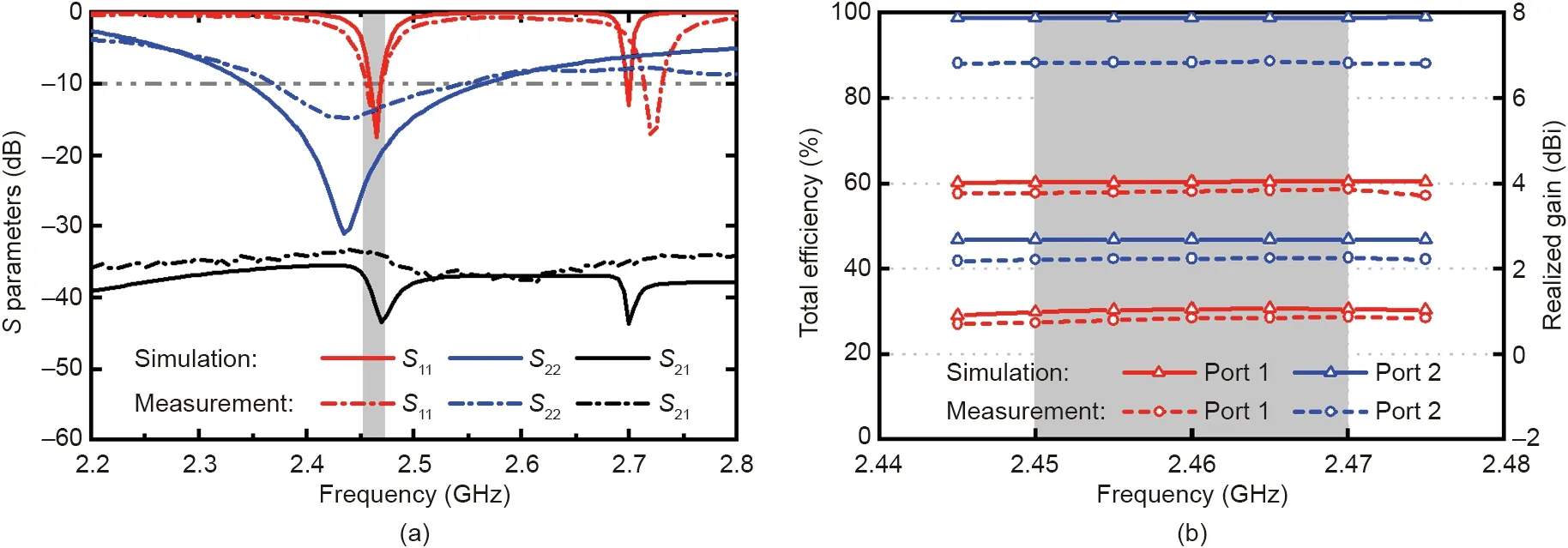
Fig.6. (a)S parameters,and(b)realized gain and total efficiency of the propounded ODP antenna in simulated and measured results.|SMN|represents the received signal level from port M when the signal is transmitted through port N; dBi represents the gain relative to an isotropic antenna.
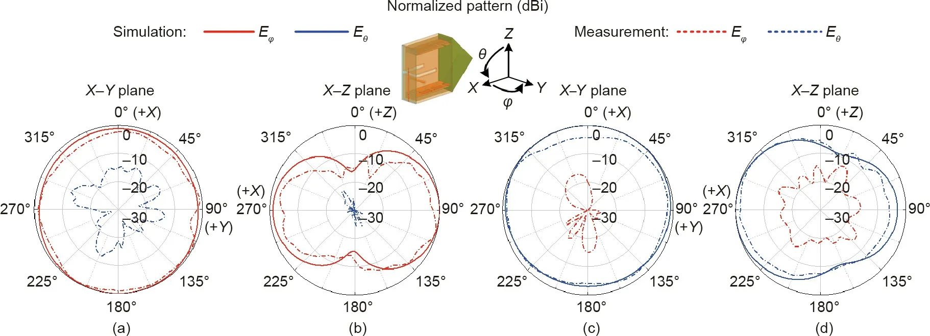
Fig. 7. Normalized radiation patterns of the propounded antenna in measured and simulated results: (a, b) horizontal polarization; (c, d) vertical polarization. Eφ and Eθ represent the φ and θ components of the electric fields,respectively.φ is the azimuth angle relative to the X-axis in the X-Y plane,and θ is the elevated angle relative to the Zaxis.

Table 2 Property comparison.
The variation of the radiation pattern is a critical index in ODP antennas used for omnidirectional coverage. Fig. 8 depicts the parametric study on the width of cavity l3that impacts the radiation patterns.When l3decreases from 12 to 6 mm,the metal cavity imposes a less pronounced blocking effect on the backward radiation from the equivalent magnetic current, hence improving the omnidirectional radiation properties for horizontal polarization,as demonstrated in Fig. 8. However, the cavity width l3is limited by the inserted metasurfaces, and the optimized parameter here is l3= 9 mm.
The length of the propounded cavity l1is λ0/4. By tuning the feeding probe’s position, the thin cavity operates at the quartersinusoidal mode along the X-axis,and the zeroth-order mode along the Z-axis when fed by port 1.As depicted in Fig.9(a),the uniform electric field distribution is achieved in most radiation aperture areas. Fig. 9(b) shows the field magnitude distribution along the centerline(AA′)with the peak values at points Paor Pd.This implies that a strong resonance exists inside the dual-layer metasurfaces.The electric field becomes uniform from point Pbto Pc,thus implying that the metasurfaces operate as the AMC boundaries. Therefore, a uniform, equivalent magnetic current is achieved with azimuthally omnidirectional radiation. It is worth noting that the lossy metasurfaces reduce the efficiency of the horizontal polarization and limit the impedance bandwidth. Fig. 9(c) indicates the simulated reflection coefficients of port 1 with various values of l2. When l2increases from 30 to 70 mm, the resonant frequency is stable with a wider impedance bandwidth,owing to the reduced quality factor associated with the cavity volume.Consequently,the height l2is optimized as a compromise between bandwidth and dimensions.
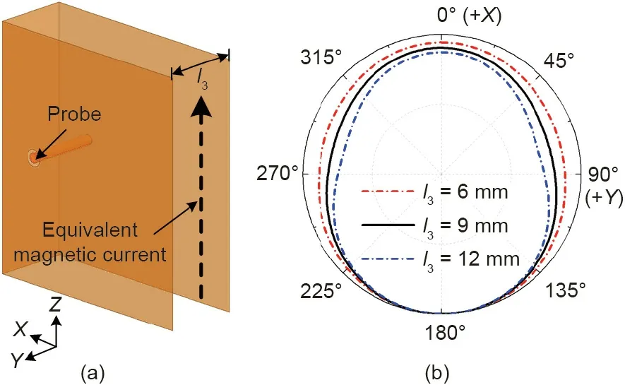
Fig. 8. Study on the influence of parameter l3 affecting the gain variation of the radiation pattern. (a) Configuration of the regular antenna A; (b) normalized radiation patterns in X-Y plane with various values of l3 at 2.465 GHz.

Fig.9. Uniform electric field property at the open end of the horizontal-polarized cavity.(a)Surface electric field magnitude|E|at 2.465 GHz;(b)centerline(AA′)electric field magnitude at 2.465 GHz; (c) |S11| of the propounded antenna with various values of l2.
4.2. Parametric analysis for aerodynamic property
As depicted in Fig. 10, the propounded antenna mounted on the scaled F-15 fighter model is designed and numerically studied by the commercial software Altair HyperWorks FEKO 2017.1 (Altair, USA). The maximum flight velocity of the practical F-15 fighter can reach 2.5 Ma (1 Ma ≈306 m∙s-1at an altitude of 10 km), with a fuselage length of 19.45 m, a wing-span of 13.05 m, and a height of 5.65 m. From the perspective of electromagnetics, the fighter fuselage is regarded as a large metal ground. When the fuselage is large enough relative to the antenna, the scaled size of the fuselage has a minor influence on the electromagnetic property of the system. Hence, owing to the limits of the numerical computation resources, the F-15 fighter is scaled to one twentieth of its original size with the simplified metal fuselage denoted by the orange highlighted area shown in Fig. 10(a). The numerical results are still instructive and adopted to verify the electromagnetics and aerodynamics designs. The propounded antenna with the wedge-shaped block is directly mounted on the fuselage of the scaled fighter model.Figs. 10(b) and (c) show the three-dimensional radiation characteristics for horizontal and vertical polarizations at 2.465 GHz.One can observe that the radiation patterns tilt upwards for both polarizations owing to the metal fuselage, and the propounded ODP antenna maintains the same modes with a slight offset in the operating frequency. In Eq. (4), the windage force is also related to CD(i.e., the windage coefficient). Apart from the antenna’s shape, the windage coefficient is also closely inter-related with the velocity of the antenna relative to the fluid. For example, in subsonic-speed situations, a water-drop-like object has the smallest windage coefficient. However, in supersonic-speed flight, the water-drop-like object would contribute a normal shock wave yields to a large windage coefficient. Subject to this supersonic circumstance, a wedge-shaped object would trigger the oblique shock wave whose windage coefficient can be reduced to the minimum value compared with other shock waves.
Thus, to reduce the windage coefficient of the propounded antenna, a conformal block (εr= 1) with the sharp angle α is attached to the cavity, as plotted in Fig. 11(a). The general view of the airflow direction and the placement angle of the antenna are illustrated in Fig. 11(b). Different windage coefficient values are achieved as the sharp angle α changes. Considering the state with the relative velocity va= 2 Ma and the flight altitude h = 10 km, the propounded antennas with and without the block are numerically calculated. Figs. 11(c)–(f) display several pressure nephograms in different states.The antenna volumes and windage coefficients with different values of sharp angle α are shown in Fig.12.The propounded antenna without a block has quite a large windage coefficient CD=1.743.By attaching the block,the windage coefficient dwindles from 1.513 to 0.828 as the angle α decreases from 120° to 60°. However, the volume of the antenna would be larger as the angle α decreases. Considering the trade-off between the volume and the windage coefficient, the sharp angle α is chosen to be equal to 90°with a windage coefficient CD=1.237.Overall, the windage coefficient of the propounded antenna is reduced by 29.6% than the antenna without the block, while the crosssectional area remains unchanged.
5. Conclusions

Fig. 10. Radiation patterns of the propounded antenna on the fighter model at 2.465 GHz. (a) Simulated model; (b) three-dimensional horizontally polarized radiation pattern; (c) three-dimensional vertically polarized radiation pattern.
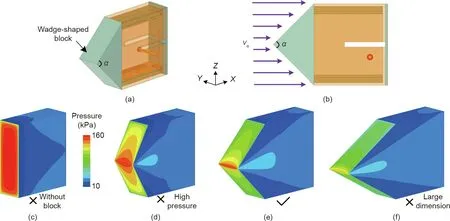
Fig.11. Geometry and aerodynamics property of the propounded antenna with the wedge-shaped block.(a)Perspective view of the propounded antenna;(b)diagram of the airflow direction;(c)pressure nephogram without the block;(d)pressure nephogram loading the blocks with angle of 120°;(e)pressure nephogram loading the blocks with angle of 90°; (f) pressure nephogram loading the blocks with angle of 60°.α: the sharp angle of the wedge-shaped block;va: the relative velocity.
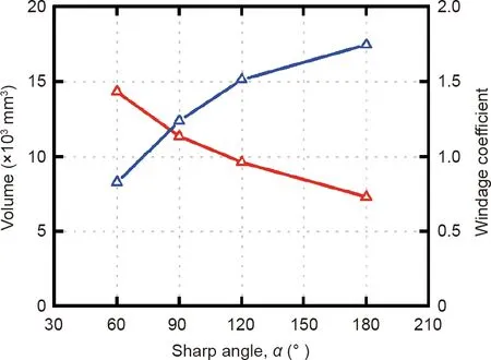
Fig. 12. Antenna volumes and windage coefficients with different values of sharp angle α.
In this article, a low-windage ODP antenna system is propounded for metallic surface installation for high-speed onboard applications. For the electromagnetic property, a saber-like cavity with inserted metasurfaces is propounded for horizontally polarized radiation, and a conformal slot is carved for vertically polarized radiation, thus leading to an increased isolation (higher than 33 dB).Measurements of the realized gain variations less than 4 dB are acceptable for practical applications.For the aerodynamics performance, a wedge-shaped block with a sharp angle of 90° is attached to the antenna, thus reducing the windage coefficient by 29.6% in high-speed flights. In view of the merits of low windage, direct fuselage installation, compact size, high-polarization isolation, and azimuthally omnidirectional coverage, the propounded antenna diversity system exhibits a promising potential for high-speed, low-windage onboard communications.
Acknowledgments
The authors acknowledge the support from the Natural Science Foundation of Beijing Manipulate (4182029), the Youth Top Program of Beijing Outstanding Talent Funding Project, and the National Key Research and Development Program of China(2018YFB1801603).
Compliance with ethics guidelines
Yongjian Zhang, Yue Li, Weiquan Zhang, Zhijun Zhang, and Zhenghe Feng declare that they have no conflict of interest or financial conflicts to disclose.
- Engineering的其它文章
- COP26: Some Progress, But Nations Still Fiddling While World Warms
- Creating a Research Enterprise Framework for Transdisciplinary Networking to Address the Food–Energy–Water Nexus
- Fabrication of a Hydrophobic Hierarchical Surface on Shale Using Modified Nano-SiO2 for Strengthening the Wellbore Wall in Drilling Engineering
- Emerging Organic Contaminants in Chinese Surface Water:Identification of Priority Pollutants
- Advanced Antennas Push Forward Wireless Connectivity
- Wide-Angle Scanning Antennas for Millimeter-Wave 5G Applications

