Prospects of Huygens’ Metasurfaces for Antenna Applications
George V. Eleftheriades, Minseok Kim, Vasileios G. Ataloglou, Ayman H. Dorrah
Department of Electrical and Computer Engineering, University of Toronto, Toronto, ON M5S 3G8, Canada
1. Introduction
In recent years,there has been an intense research effort by the international community in the field of‘‘artificial”electromagnetic materials,or‘‘metamaterials.”Metamaterials are engineered structures that induce a tailored arrangement of magnetic and electric dipole moments when excited by an incident electromagnetic field. Under certain conditions, such as when the comprising unit cells are sub-wavelength, metamaterials can be homogenized and described in terms of macroscopic constitutive parameters such as permeability, permittivity, and refractive index. A summary of the early work on ‘‘artificial dielectrics” can be found in Ref.[1].In the over 20-year-old field of metamaterials,the desired macroscopic parameters correspond to extreme properties such as negative permittivity,negative permeability,and a negative refractive index. Perhaps the most recognized metamaterial is that which realizes a negative refractive index,originally demonstrated at microwaves and based on a unit cell made out of a split-ring resonator and a wire [2]. In the engineering community, a transmission-line approach was developed for implementing metamaterials with significant advantages, such as reduced transmission losses and wider operating bandwidths [3,4].
In the context of metamaterials, metasurfaces can be considered as two-dimensional (2D) metamaterials. It is perhaps noteworthy that most of the research on metasurfaces was conducted following the work on three-dimensional (3D) metamaterials [5–9].In this article,we focus on the concept of the Huygens’metasurface (HMS) and its application to antenna engineering. HMSs are composed of 2D arrays of Huygens’ scatterers or sources, giving rise to passive and active HMSs, respectively. In their most basic form,these HMSs are implemented by co-located orthogonal electric and magnetic dipole moments (or currents) [6,7]. Such 2D metasurfaces are homogenized with macroscopic parameters such as surface susceptibility or impedance/admittance tensors, since there is no volume to properly define constitutive parameters such as permeability or permittivity. The important aspect here is that the wave nature of light can be understood using secondary sources(Huygens’sources)and emanating wavelets,as envisioned by Christiaan Huygens dating back to the 17th century. Hence,HMSs offer a powerful method to engineer and control electromagnetic wavefronts at will.Consequently,there is ample opportunity to apply these HMSs to antenna theory and practice, as will be highlighted in the remainder of this short article.
2. Basic HMS theory
Fig. 1 shows the basic setup for formulating the theory of an HMS. As shown, an incident electromagnetic wave consisting of an electric field E1and a magnetic field H1is transformed into a desired transmitted wave with electric field E2and a magnetic field H2by passing through a thin HMS surface. This transformation is achieved by exciting suitable orthogonal electric and magnetic currents, denoted by Jsand Msrespectively, as shown in Eq. (1).

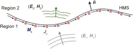
Fig.1. Schematicofa genericHMS.The surfacecurrentdensities Js and Ms allowfor adiscontinuityinthe fields (E1,H1)and (E2,H2)atthetwosides of the HMS.E1 and H1 are the electric and magnetic fields at the input side (region 1),respectively. E2 and H2 are the electricand magnetic fields at the transmittedside (region 2),respectively.n︿ istheunitvector normalto the HMS pointingtowards region 2.
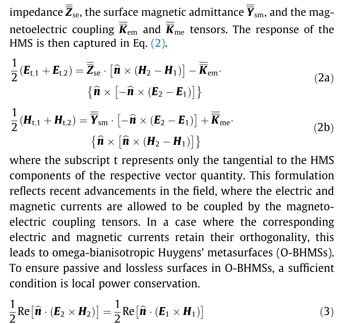
where Re refers to the real part of the normal power density.The extra degree of freedom offered by omega-bianisotropy enables the total control of the reflections in region 1(Fig.1).For example,O-BHMs have been used to demonstrate reflectionless refraction even when the angle of incidence and refraction are greatly different, which is a significant milestone in the development of such metasurfaces [11].
3. Antenna beamforming
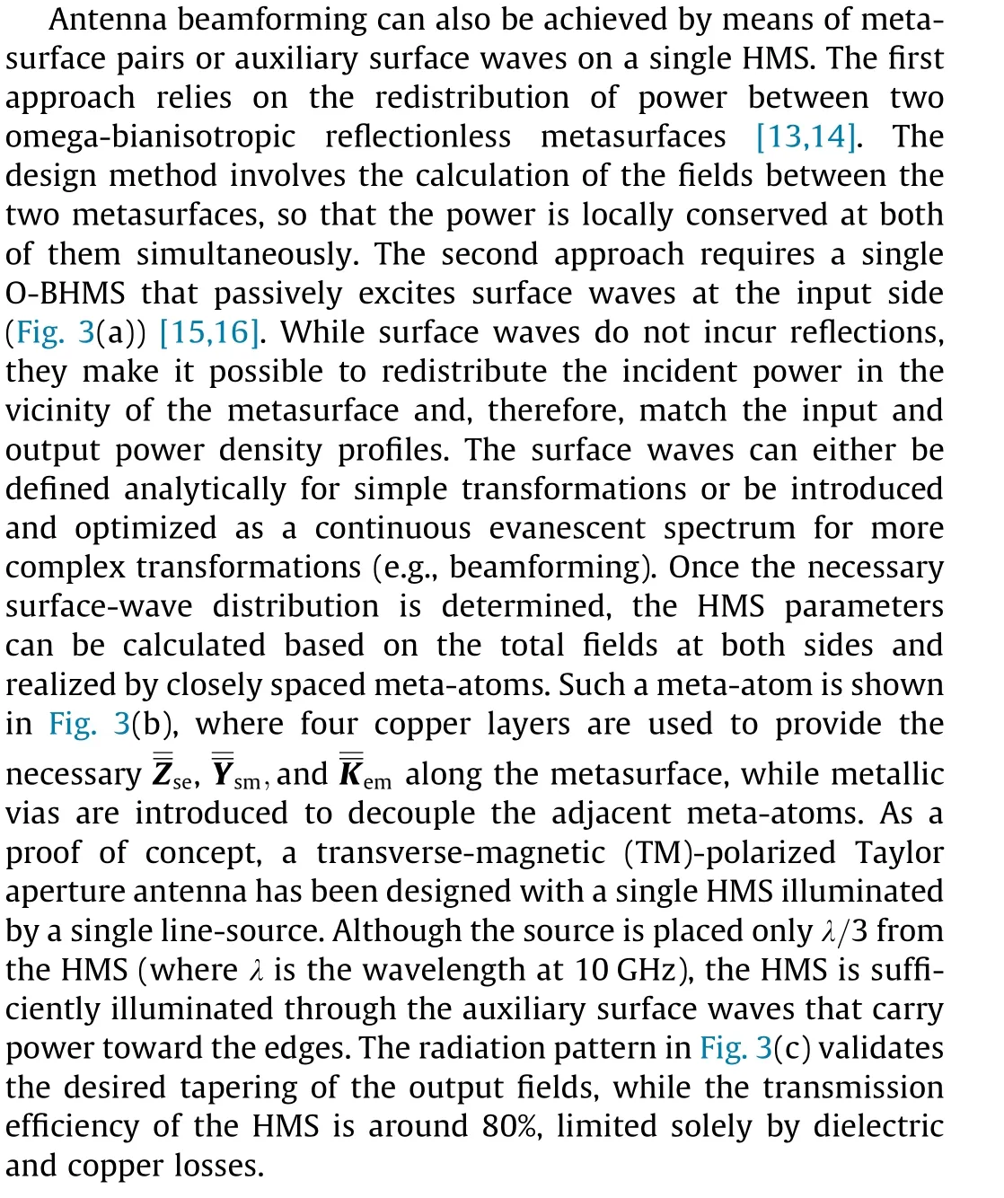
One appealing application of HMSs in antennas is antenna beamforming. In particular, HMSs can be utilized for antenna beamforming with precise pattern control,but without the explicit utilization of a feeding network as in conventional antenna arrays.Although the general formulation in Eq. (2) would seem to allow for arbitrary amplitude and phase control over a given metasurface aperture, the requirement of local power conservation in Eq. (3)imposes a severe restriction on such arbitrary magnitude and phase control. One solution to this issue is to allow reflections to occur in order to taper the amplitude of the refracted waves to become arbitrary. In order to recover this otherwise lost reflected power, the metasurface can be enclosed in an oversized cavity[12]. As shown in Fig. 2 [12], the cavity is excited by a current source element in close proximity to the radiating metasurface aperture. It should also be noted that the reflections in the cavity permit the efficient illumination of the aperture, thus providing an increased gain as desirable.
4. Electronic beamforming and steering

Fig. 2. Cavity-excited HMS for antenna beamforming [12]. (a) Sketch of the structure. x,y,and z refer to a cartesian coordinate system. δ is the Dirac function. θout is a desirable transmission angle. A current source J with amplitude I0 is placed at y=y′, z=z′ within a cavity of length L and depth d. Radiation towards θout is obtained.(b)Fabricated antenna for highly directive radiation at the broadside.λ is the free-space wavelength.(c)Measured,theoretical,and simulated patterns at 20 GHz in decibels(dB).

Fig.3. Single O-BHMS for beamforming applications through auxiliary surface waves.(a)Sketch of the configuration[16].Incident electric field Einc and magnetic field Hinc is transformed to desired output electric field Eout and magnetic field Hout by means of auxiliary surface waves characterized by an electric field Esw and magnetic field Hsw.(b)Sample unit cell to realize the HMS parameters.Four dogbone layers with widths W1,W2,W3,and W4 are etched on Rogers RO3010 substrates.(c)Radiation pattern from physical structure simulations for a Taylor pattern with a –20 dB sidelobe level.φ represents the angle in the azimuthal (x–y) plane.
As previously mentioned, one of the unique field manipulation capabilities of O-BHMSs is ‘‘perfect” refraction, in which an incident electromagnetic (EM) wave can be arbitrarily refracted even at extreme angles without producing any spurious diffraction[11,17]. For example, by asymmetrically placing a wire and a loop to form an omega-bianisotropic Huygens’ unit cell, Chen and Eleftheriades [17] experimentally demonstrated the refraction of a normally incident EM wave at 72° with negligible reflections,as shown in Fig. 4 [17]. Such an unusual field manipulation capability is of particular interest in many antenna applications,since it can be used as a new paradigm for realizing a wide-angle scanning antenna. Indeed, Abdo-Sánchez et al. [18] utilized the unique refraction properties of O-BHMS in the implementation of a leaky-wave antenna (LWA) to demonstrate arbitrary control of the guided and leaky modes.In their work,these scholars replaced the top perfect electric conductor plate of a parallel-plate waveguide with an O-BHMS such that an arbitrarily stipulated guided mode could be transformed into a certain desired leaky mode.Since the guided mode and the leaky mode are user-defined quantities, their proposed LWA can radiate in any direction (including broadside) with arbitrary leakage constants. The ability to control the leakage constant also implies that a certain amplitude tapering can be synthesized on the O-BHMS to realize complex radiation patterns (e.g., a Dolph–Chebyshev pattern). Notwithstanding,many practical applications such as high-speed communications,radar, and remote sensing also require the dynamic control of radiation patterns. Consequently, significant effort has been devoted recently to the implementation of reconfigurable metasurfaces for the dynamic shaping of EM waves [19–23]. For example,Chen et al. [19] demonstrated a tunable Huygens’ metalens by incorporating three varactor diodes in each of their wire-loop unit cells. By individually biasing these diodes, the researchers could independently control the electric and magnetic resonances,thereby achieving the required phase control for tailoring the focused beam profiles. In comparison, so-called ‘‘1-bit” tunable metasurfaces have also been frequently demonstrated to dynamically steer multiple beams, which typically utilize positive–intrinsic–negative (PIN) diode switches in their unit-cell design [20,21].These surfaces, however, inevitably produce more than one beam when they are excited by normally incident plane waves,and most of the reported 1 bit metasurfaces are reflective,as the biasing network can easily be integrated behind a ground plane.In addition to these phase-only tunable metasurfaces, it should be briefly mentioned that surfaces that can dynamically alter the polarization state have also been demonstrated [22,23]. While the aforementioned tunable metasurfaces are capable of dynamic beam shaping,they still provide limited wave-control capabilities due to their inability to independently modulate the amplitude of the scattered field. Such functionality is highly desirable, as it would offer extreme capability for precise beamforming. In addition, most of the reported tunable surfaces have focused on dynamically manipulating free-space waves, which requires an external excitation source to be placed sufficiently far away from the surfaces. To address these issues, Kim and Eleftheriades [24] introduced a reconfigurable O-BHMS that can be integrated with a wave-guiding structure to realize a compact wave-control platform,as shown in Fig.5[24].The proposed tunable O-BHMS is capable of independently controlling the amplitude and phase of its reflection and transmission coefficients, thereby supporting an arbitrarily stipulated guided mode (i.e., there is no cutoff frequency) and any desired radiations.To be specific,this is achieved by cascading four tunable impedance surfaces.Each tunable impedance surface consists of dual-loop unit cells in which a varactor diode is integrated with the outermost loop to acquire the necessary tunability (Fig.5(a) [24]). The unique feature of their proposed unit cell is that its reactance can be widely tuned from inductance to capacitance as a function of the applied bias voltage, which makes it possible to synthesize arbitrary scattering parameters for the cascaded structure.As a proof of concept,Fig.5(c)shows the numerical simulation results of wide-angle scanning from–70°to 70°at the fixed operating frequency of 5 GHz. In contrast to traditional phased arrays,which struggle to scan at extreme angles due to the mutual coupling between elements, wide-angle scanning could be achieved,since the O-BHMS directly satisfies the necessary boundary conditions for any given field distributions to be fully Maxwellian.These unique attributes of a tunable O-BHMS are particularly interesting for various emerging applications such as the fifth generation mobile communication technology (5G)/the sixth generation mobile networks (6G) telecommunications, radars for autonomous vehicles, and traffic control.
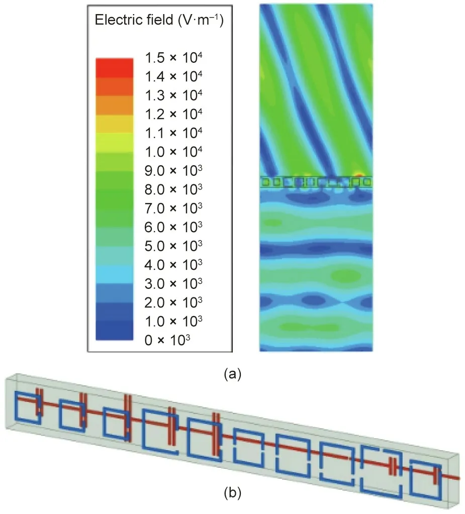
Fig. 4. Reflectionless wide-angle refraction based on an O-BHMS. (a) Electric field distribution of one period of the O-BHMS showing anomalous refraction of a normally incident wave at 72°;(b)the physical realization of the O-BHMS based on the asymmetric wire-loop design.Reproduced from Ref.[17]with permission from IEEE, © 2020.
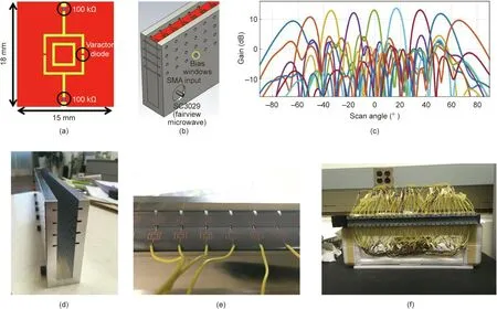
Fig. 5. O-BHMS-assisted LWA. (a) The proposed unit cell design and (b) the schematic of the LWA that integrates the tunable O-BHMS [24]. SMA: subminiature version A.(c) Full-wave simulation results on gain variation at various scan angles. (d–f) The fabrication of the proposed reconfigurable LWA.
5. The peripherally excited Huygens’ box antenna
One of the first reports on HMSs involved the usage of an active HMS for cloaking applications [7,10]. This concept has also been utilized to excite unusual electromagnetic modes in an oversized metallic cavity lined by active Huygens’sources[25,26].For example,Wong and Eleftheriades[26]experimentally show how such a Huygens’ box arrangement can produce traveling waves at arbitrary angles in a rectangular closed metallic cavity(box).It is worth highlighting that these traveling waves are not from the inherent modes of metallic cavities,which are typically only capable of supporting standing waves. This feat becomes possible since the excited fields inside the metallic cavity of the Huygens’ box can be controlled by the peripheral Huygens’ sources (along the perimeter of the cavity) according to the equivalence principle.This Huygens’box device has been utilized to demonstrate the formation of sub-wavelength focal spots and cloaking [26]. More recently,the same concept was exploited to realize reconfigurable aperture antennas with a reduced number of active elements, as the number of active elements therein is no longer dependent on the area of the radiating aperture (N2dependence, where N2is the number of antenna elements) and is instead solely dependent on its circumference (N dependence) [27,28]. Fig. 6(a) shows a possible realization of this peripherally excited phased array(PEX-PA)concept.As shown,a cavity is lined up by active Huygens’sources,which can comprise simple dipole antennas backed up by the cavity side walls.The top surface of the cavity is a perforated or suitably slotted metallic plate that allows radiation to leak out. A prototype of the PEX-PA concept was fabricated using standard printed-circuit board fabrication technology, as shown in Fig. 6(b);the side walls of the cavity were constructed using metallic vias connecting the top and bottom plates of the board, and the radiating perforations were arranged in a 2D square lattice.Sample measured radiation patterns are depicted in Fig. 7 for single-beam operation and in Fig. 8 for multiple-beam operation. It is observed that the designed structure is capable of generating single and multiple pencil beams at broadside and tilted angles in different scan planes. This finding demonstrates the flexibility of the PEX-PA concept and the possibility of generating directive pencil beams solely from peripheral Huygens’ sources excitations. In principle, by controlling the phase and/or magnitude of these peripheral sources, the generated beam(s) can be scanned over a considerable range of angles.
6. Discussion and conclusions
HMSs offer great opportunities for advances in antenna theory and practice. Some opportunities have been highlighted in this article and include static beamforming without a feeding network but still with precise aperture and phase control.HMSs can also be used for dynamic beamforming and beam steering with an inherent capability of wide-angle scanning. We expect this latter attribute to be further exploited and demonstrated in the future.Another important characteristic of these surfaces is that they can be designed to achieve all-pass filtering characteristics [29].This attribute can be exploited in the future for ultra-wideband antenna applications with ultra-thin HMS apertures. Dynamic HMSs also permit low power consumption due to their compatibility with simple controlling elements, such as varactors. Moreover,the concept of the peripherally excited (PEX) Huygens’ box antenna offers an alternative to phased arrays but with a drastically reduced number of active elements.This concept is also likely to be further exploited and demonstrated in the future.Finally,time-modulated HMSs can be envisioned as offering opportunities for non-reciprocal antenna applications, such as for fullduplex 6G wireless networks [30].
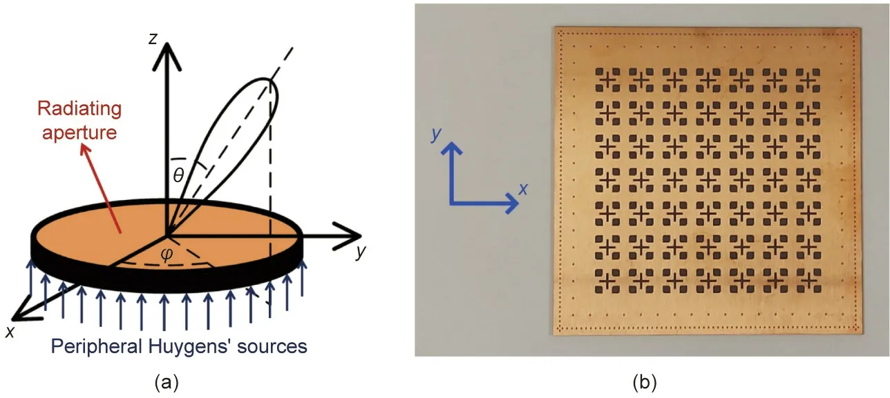
Fig. 6. The peripherally excited cavity antenna. (a) Demonstration of the concept. θ: the elevation angle. (b) Fabricated square prototype.

Fig. 7. Examples of measured radiation patterns at 13 GHz. (a) Broadside; (b) titled close to the x–z plane; (c) titled close to the y–z plane.

Fig.8. Examples of measured multiple-beam radiation patterns at 13.1 GHz.These plots show the normalized 3D radiation field intensity patterns to an arbitrary value of 100(V∙m-1) in linear scale.
- Engineering的其它文章
- COP26: Some Progress, But Nations Still Fiddling While World Warms
- Creating a Research Enterprise Framework for Transdisciplinary Networking to Address the Food–Energy–Water Nexus
- Fabrication of a Hydrophobic Hierarchical Surface on Shale Using Modified Nano-SiO2 for Strengthening the Wellbore Wall in Drilling Engineering
- Emerging Organic Contaminants in Chinese Surface Water:Identification of Priority Pollutants
- Advanced Antennas Push Forward Wireless Connectivity
- Wide-Angle Scanning Antennas for Millimeter-Wave 5G Applications

