
Numerical analysis on the influence of vortex motion in a reverse Stairmand cyclone separator by using LES model
2022-06-02 05:01:02ZhuWeiGoZhongXinLiuYoDongWeiChengXinLiShiHoWngXinYuQiWeiHung
Petroleum Science 2022年2期
Zhu-Wei Go ,Zhong-Xin Liu ,Yo-Dong Wei ,Cheng-Xin Li ,Shi-Ho Wng ,Xin-Yu Qi ,Wei Hung
a School of Chemical Engineering and Technology,Hainan University,Haikou,570228,PR China
b State Key Laboratory of Heavy Oil Processing,China University of Petroleum,Beijing,102249,PR China
c Beijing Key Laboratory of Process Fluid Filtration and Separation,Beijing,102249,PR China
d State Key Laboratory of Marine Resource Utilization in South China Sea,College of Materials and Chemical Engineering,Hainan University,Haikou,570228,PR China
Keywords:Numerical simulation Cyclone separator Mathematical analysis Vortex motion Local analysis
ABSTRACT This study aims to analyze the influence of vortex motion in a reverse Stairmand cyclone separator by using LES model.The mathematical analysis indicated that the energy dissipation and the flow characteristics of incompressible fluid are directly related to on the vortex motion.The results of the Q criterion-based iso-vortex surface could well reflect the tendency of the vortex structure,in which the iso-vortex surface exhibited a distorted distribution rather than around the center axis.At the turning point of velocity vector,vortices were formed and developed,and the point was the center of the local vortex core.In addition,the vortex formed an irregular annular region around the wall at the bottom of vortex finder.The vortex structure near the dust hopper presented a strong distortion.Moreover,there were two rotating flow in the opposite direction within the dust hopper.These phenomena would affect the separation performance,which was significance to cyclone separator.
1.Introduction
As a basic centrifugal separation equipment,cyclone separator is widely used for various separation fields (Gao et al.,2019).Fig.1 shows the schematic diagram of a reverse Stairmand cyclone separator.The internal flow field(Beaumont et al.,2017;Yue et al.,2019) of cyclone separator have an essential impact on the separation process(Zhou et al.,2020;De Souza et al.,2015;Demir et al.,2016;Jia et al.,2019).Previous research of flow field mainly focused on improving the separation performance of cyclone separator.For the internal flow field of cyclone separator,the motion of fluid element is the foundation of analyzing the separation process(Derksen and Van Den Akker,2000) and establishing the theoretical model of multiphase separation (Song et al.,2017;Su et al.,2011),especially the motion of vortex.
In practical application,the internal flow of the cyclone separator is unstable due to the Rankine vortex structure of rotating flow (Cortes and Gil,2007).The unbalance would cause energy dissipation and various industrial problems (Gao et al.,2010).The measurement of the transient flow field and the theoretical analysis of fluid element are common used methods to analyze the flow field.Over the past years,many researchers have improved the vortex performance of cyclone separator in their studies.Hoekstra et al.(1999) revealed that the so-called processing vortex core(PVC)existed in a cyclone separator.The PVC mainly existed in the area near the dust hopper,and its frequency was close to a constant and proportional to the inlet gas velocity.Near the dust hopper,the vortex core formed a high-intensity eccentric swing.The study of Derksen et al.(Derksen and Van Den Akker,2000;Derksen,2005)indicated that the flow field was in a quasi-periodic state and exhibited a peak in the spectrum.Solero and Coghe (2002) used a LDV to measure the flow inside cyclone.The results demonstrated that there was a frequency of rotation from spectral analysis of the fluctuations.The research of Obermair et al.(2003) used the LES model and discovered that the vortex core deviation had a maximum value.The study of Peng et al.(2005) showed that the frequency varied with the gas flow rate in cyclone separator.The experiment of Gu et al.(2016)monitored the pressure fluctuations,revealing that there were two dominant frequencies,and the second dominant frequency was not an integer multiple of the primary dominant frequency.The PDPA results of Gao et al.(2019a,b) suggested that the vortex motion in cyclone separator was unstable.
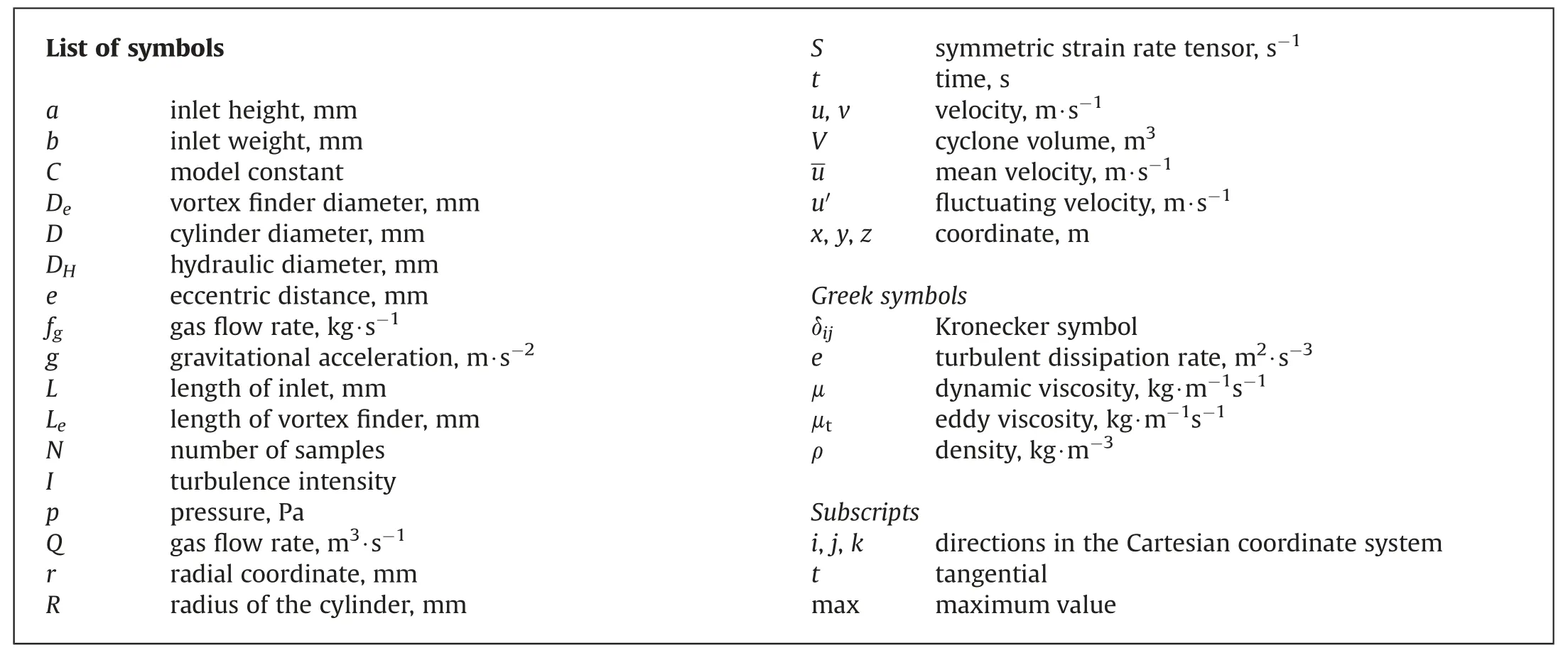
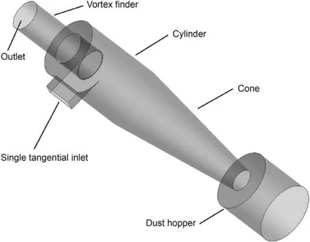
Fig.1.Schematic diagram of the cyclone separator.
With the development of computer technology,the computational fluid dynamics (CFD) is widely used in flow-field analysis.The Reynolds stress model (RSM) and the large eddy simulation(LES)have been verified with accurate simulation of cyclones(Brar et al.,2015;Lim et al.,2020;Wei et al.,2020;Le and Yoon,2020;Jia et al.,2019;Misiulia et al.,2020;Shastri and Brar,2020).The former provides time-averaged results,while the latter provides spaceaveraged results.The study of Gronald and Derksen (2011) used the LES model to simulate the flow in a cyclone separator,and their results demonstrated that there was no apparent frequency in the dust hopper.Shukla et al.(2013) compared RSM model and LES model,and found that the LES model was better to simulate the transient characteristics of the flow field.The experimental and simulated results of Gao et al.,(2019;2020;2019)indicated that the vortex motion could be adjusted by changing the structure of the entrance structure.These works enriched the understanding of vortex motion in cyclone separator.
Scholars have carried out a lot of experimental research and numerical simulation on the internal flow field of cyclone separator,and achieved some good results.However,previous studies mainly rely on the tangential velocity or axial velocity to estimate the motion of vortex,deficient in mathematical analysis and theoretical support.Moreover,many studies mostly focus on the PVC phenomenon or the instantaneous tangential velocity distribution while neglecting a deeper analysis of the vortex motion.
The present study is conducted to assess the vortex motion in a reverse Stairmand cyclone separator with single tangential inlet structure.The LES model is adopted to investigate the flow behavior.The mathematical analysis is performed to explore the vortex motion in the cyclone separator.In addition,the Q criterion is proposed to identify the vortex structure.The key to this work is to understand the identification of vortex structure and the mathematical analysis of the vortex motion.
2.Model description
2.1.Geometric model
Fig.2 illustrates the structure of a reverse Stairmand cyclone separator with single tangential inlet structure.The structure and dimension in this study are in accordance with the geometry adopted by Hoekstra (Hoekstra and thesis,2000).The basic dimensions are listed in Table 1,corresponding to the structure presented in Fig.2.

Table 1The physical dimensions of the cyclone separator configurations used in this study.
2.2.Turbulence model
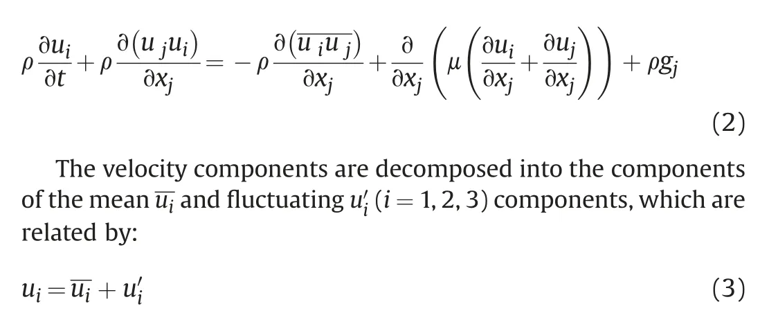
For a centrifugal separator,the governing equations of cyclone can be expressed as:

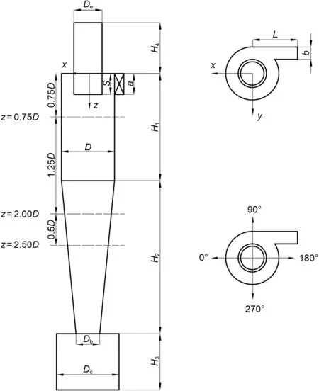
Fig.2.Structure of a reverse Stairmand cyclone separator with single tangential inlet structure.
Many studies (Parvaz et al.,2018;Tofighian et al.,2020;Sun et al.,2017;Siadaty et al.2017,2018;Brar and Elsayed,2018;Nassaj et al.,2019;Balestrin et al.,2017) have been conducted and revealed that the Reynolds stress model(RSM)and the Large-eddy simulation(LES)have good effect on the simulation of the internal flow of cyclone separator.To make the visualization effect of vortex motion better,the LES model is selected to study the vortex motion of the reverse Stairmand cyclone separator in this study.
In LES model,the instantaneous velocity uiis decomposed into a resolvable-scale filtered velocityand sub-grid-scale (SGS) velocity,that is,The finite-volume discretization itself provides the filtering operation as:

Where V denotes the volume of a computational cell,x′represents actual spatial coordinates,and x indicates the filtered spatial coordinates.G(x,x′) is the filter function defined as:

When the filtering operation is applied to the continuity and Navier-Stokes equations,it can be obtained that
In Smagorinsky-Lily model,SGS stress is defined as

2.3.Numerical method
The present study used the finite volume method to simulate the flow field.Numerical calculation was performed by using ANSYS Fluent software.According to the experiment conducted by Hoekstra (Hoekstra and thesis,2000),the inlet gas velocity is 16.1 m/s and the density of the gas is 1.225 kg/m3.The gas viscosity is 1.7894 × 10⁻⁵kg/(m·s) unless otherwise stated.For cyclone separator,the hydraulic diameter and the turbulence intensity were calculated as:
The whole system was simulated under a positive pressure,and the pressure at the outlet was 1 atm.Besides,the simulation was calculated with a transient solver method,and the time step was 10-4s.
2.4.Grid system and independence
The three-dimensional model of cyclone separator was established by the SolidWorks software.The quality of grid greatly affects the accuracy of numerical simulation.We used the ANSYS ICEM software to optimize the grid.Multi-block hexahedral structured grids were adopted to analyze the computational domain.The computational grid of the cyclone model containing 1486960 cells was exhibited in Fig.3.
Four grid domains were tested in our preliminary computation,containing 681560,1248660,1486960 and 1726860 cells,respectively.The computing result of four different densities of the grid at z/D=2 was present in Fig.4.The relative error in tangential velocity at the position of z/D=2 between 1248660 and 1486960 cells was about 5.6%,and the relative error in tangential velocity between 1486960 and 1726860 cells was less than 0.8%.Conclusive results demonstrated that the difference between the grid of 1486960 cells and 1726860 cells was small,very close to the experiment results,suggesting that computed results were independent of the characteristics of the grid size.Therefore,the grid domains of 1486960 cells were adapted in this study.
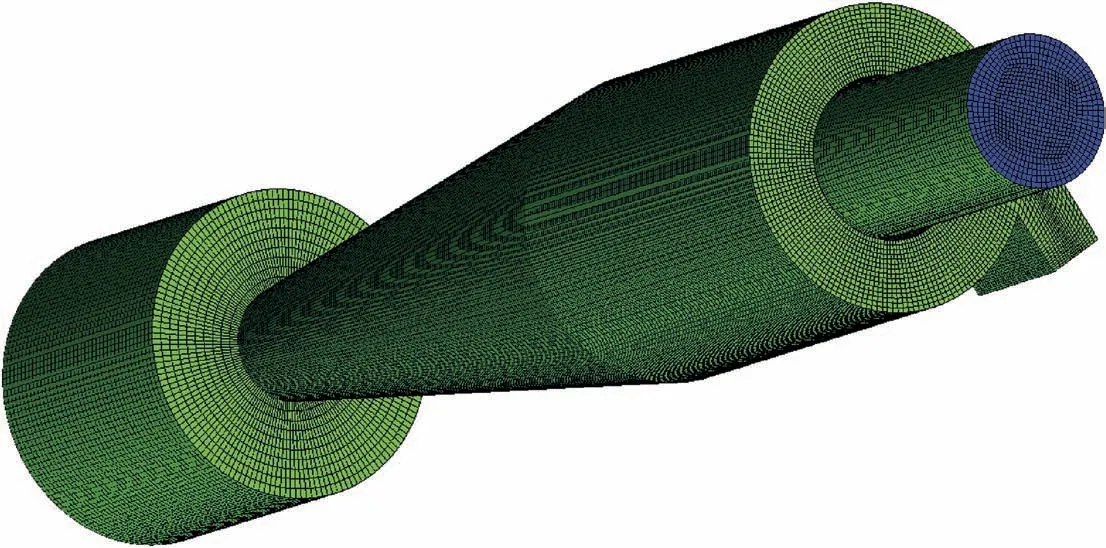
Fig.3.Computational grids containing 1486960 cells of the cyclone separator.
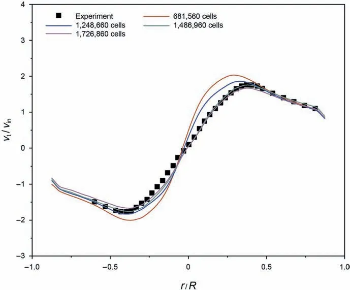
Fig.4.The tangential velocity profiles under various mesh densities at z/D=2.
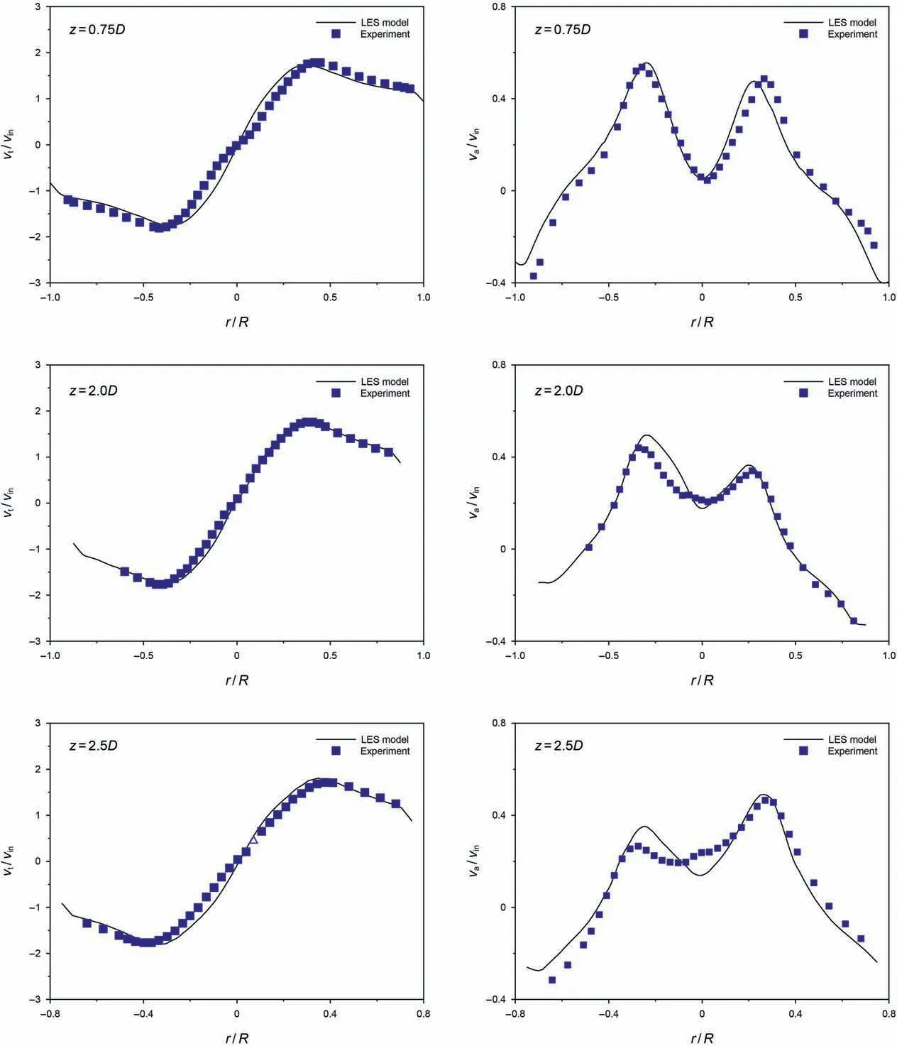
Fig.5.Comparison between predicted dimensionless mean velocity profiles and experimental data.
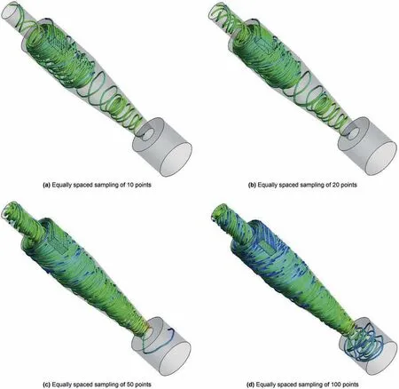
Fig.6.The stream-traces diagram within cyclone separator.
3.Results and discussion
3.1.Model validation
Time interval and number of samples are very important for model validation.The cyclone dimensions and the gas flow rate determine the average residence time in the cyclone.The average residence time is calculated as ttes=V/fg,where V is the cyclone volume and fgis the gas flow rate (Gao et al.,2014).The residence time was about 0.92 s in this study,so the time step of 1 × 10⁻⁴s was an acceptable value.In the numerical simulation calculation,there needs to be sufficient sampling data to explain (Sengupta,2021).Therefore,we use 10000 sample data after stable calculation for statistical average.
To validate the accuracy of our model established in this study,the simulation results of velocity profiles were compared with the experimental data of Hoekstra (Hoekstra and thesis,2000).Fig.5 shows the comparison between predicted dimensionless mean velocity profiles and experimental data.The numerical results exhibited good agreement with the experimental data.It indicated that the models presented here have good prediction accuracy for the flow field of cyclone separator.
3.2.The fluid motion
The internal flow field is significant for the analysis of vortex motion in cyclone separator.The stream-traces diagram within cyclone separator was illustrated in Fig.6.It shows the flow process of fluid element,which is important to understand the motion of vortex.The double-layer vortex structure of the outer vortex flow and the inner vortex flow could be observed from the stream-traces diagram of Fig.6(d).The airflow entered the cyclone separator from the inlet structure.Under the centrifugal force and the constraint of the cylindrical wall,the flow became a downward spiral motion along the wall.This downward flow was also considered the outer vortex flow.When the outer vortex flow reached the cone section,the contraction of wall made the velocity increase.Meanwhile,the pressure of outer wall continuously increased as the diameter of cone section decreased.The low-pressure area was formed in the central area of cone section.Under the pressure difference between external high pressure and internal low pressure,the airflow was close to the center and turn upwards at the bottom.The upward flow would continuously spiral until it was discharged through the vortex finder.The upward flow was also regarded as the inner vortex flow.Furthermore,stream-traces near the sidewall were not complete the spiral stream-traces.The inner vortex flow also exhibited an obvious distortion,which did not show a completely vertical shape.
3.3.The non-axisymmetry of flow
The stability of flow is essential to the separation performance in cyclone separator.In this study,four curves were compared to analyze the non-axisymmetry of flow.These curves are along the central axis to the sidewall.Their angle to the x-axis is 0°,90°,180°,and 270°,respectively,as illustrated in Fig.2.
Fig.7 shows the radial distribution of the mean tangential velocity in different axial positions.The results revealed that the mean tangential velocity of each location presented a hump structure.Values of tangential velocity in four different directions were not the same,and the mean tangential velocity profiles presented an obvious asymmetry.Overall,the symmetry of the outer vortex flow was better than that of the internal vortex flow.Although the tangential velocity profiles in different radial directions were extremely close to some axial positions,the distribution of the tangential velocity profiles in those axial positions were not the same.It indicated that the non-axisymmetry of mean tangential velocity existed in the whole space and belongs to multidimensional torsion change.
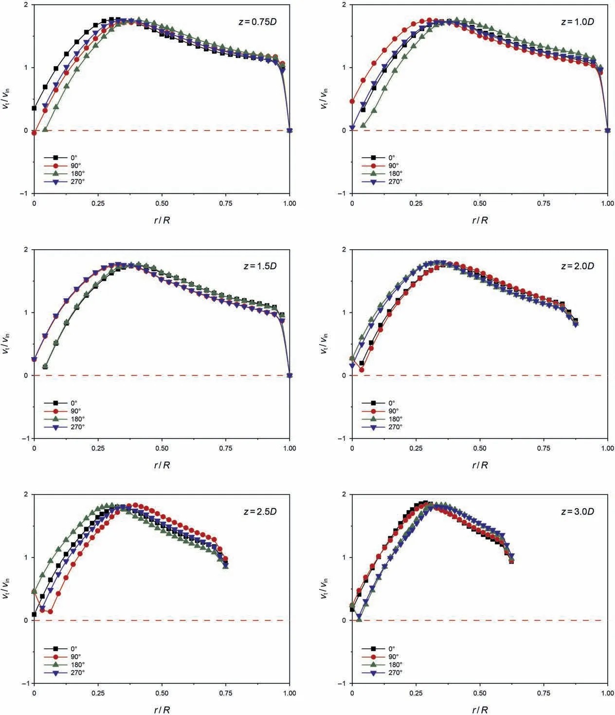
Fig.7.Radial distribution of the mean tangential velocity in different axial positions.
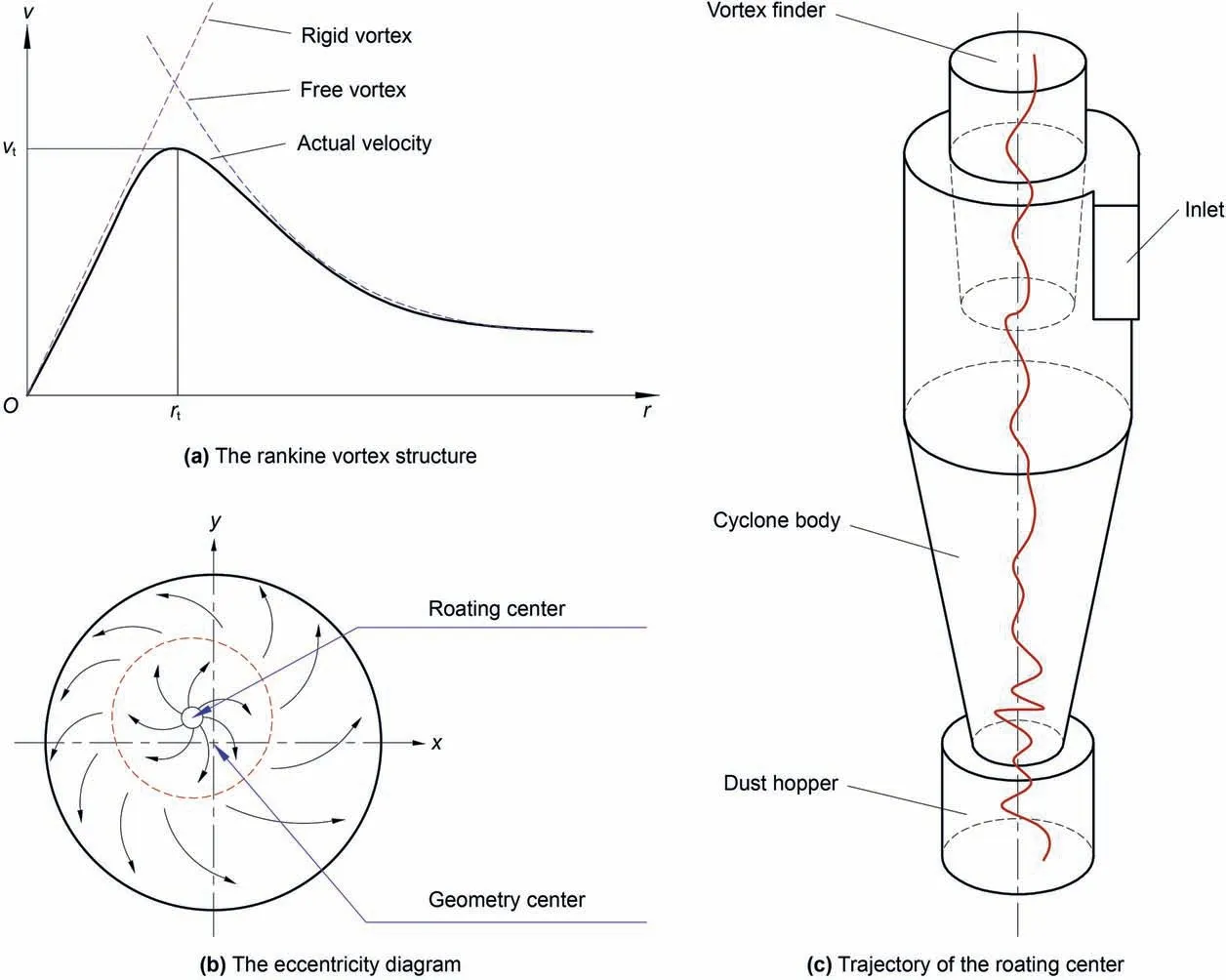
Fig.8.The eccentricity diagram in cyclone separator.
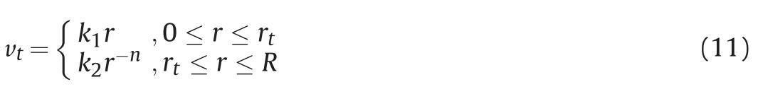
The rotating flow field inside cyclone separator is studied as a three-dimensional turbulent flow field.The tangential velocity conforms to the Rankine vortex structure,as shown in Fig.8(a).Along the radial direction,there is a free vortex on the outside and a rigid vortex on the inside with the position of the maximum tangential velocity(rt)as the boundary.Therefore,the expression of tangential velocity can be expressed as Eq.(11).In this formula,rtis generally less than the diameter of the vortex finder.
Because of the curvature effect of sidewall and the dynamic effect of rotation,the rotational flow in cyclone separator is unstable.Even for the axisymmetric geometric structure,the rotation center and the geometric center are still not coincident.These two centers has a certain deviation,as shown in Fig.8(b).Therefore,the axial line of rotation center is an irregular swing curve,as indicated by the red curve in Fig.8(c).
3.4.The velocity profile
Fig.9 shows the velocity profiles of cyclone separator.The tangential velocity contour and the velocity vectors profile partial enlarged detail resolved by the LES model were presented in Fig.9(a)and (b),respectively.The results indicated that the fluid movement was turbulence and complex.The velocity vectors profile was distorted in some areas.A large number of small-scale vortices near the wall could be observed by further observation,as shown in Fig.9(c)and(d),so as to better illustrate the complex three-dimensional flow field in the cyclone separator.This phenomenon was due to the fact that the large eddy simulation (LES) method could obtain more accurate results through the sub-grid-scale solution.
The local velocity vectors profile of the entrance and the local velocity vectors profile above the dust hopper were provided in Fig.9(c)and(d),respectively.At the bottom of the vortex finder,the short-circuit flow and secondary vortex phenomenon mentioned in previous studies were reflected in the velocity vector diagram.The vector diagram obtained by large eddy simulation indicated that the longitudinal vortices may appear in some positions,causing loss of kinetic energy and affecting the energy consumption.As can be seen from Figs.6 and 8,the fluid in the cyclone separator was a double-layer swirling turbulent flow.However,in addition to outer vortex flow and inner vortex flow,there were several vortices existed in cyclone separator.These vortices affect the flow symmetry in different degrees,such as the longitudinal circulation flow of the annular space,the short-circuiting flow near the outlet of the vortex finder,and the eccentric circulation flow near the bottom of the cone.These phenomena would affect separation efficiency and pressure drop.
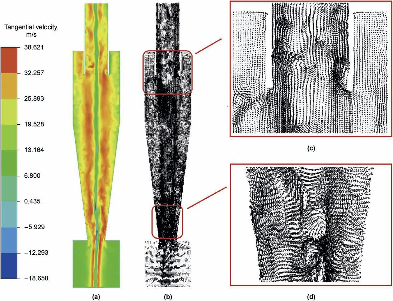
Fig.9.The velocity profiles of cyclone separator.(a) The tangential velocity contour;(b) The velocity vectors profile;(c) Local velocity vectors profile of the entrance;(d) Local velocity vectors profile above the dust hopper.
3.5.Mathematical analysis
The non-axisymmetry of swirling flow is the apparent characteristic of moving fluid,and the internal essential characteristic is the motion of vortex.In other words,the rotating fluid in cyclone separator is unstable in macro-scale,while it is the balance of vortex motion in micro-scale.In turbulence,the low-frequency large-scale vortices are energy-carrying vortices,which transfer energy to high-frequency small-scale vortices until molecules dissipate,and the energy becomes heat loss.Next,how the motion of vortex affects the swirling flow is analyzed.
The energy dissipation function of incompressible fluid per unit
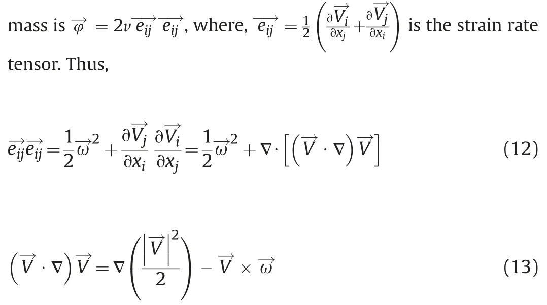
Substituting it into the above formula,it can be obtained that

By integrating Eq.(14) in the whole flow space,the energy dissipation rate function can be obtained as

When the fluid is surrounded by a stationary solid boundary and the fluid is stationary at infinity,the integral of the control surface S is zero,and the above equation can be transformed into:

Therefore,the kinetic energy dissipation rate of an incompressible fluid is directly related to the absolute value of vorticity in the fluid,suggesting that the energy dissipation and flow characteristics of incompressible fluid are directly related to the motion of vortex.
3.6.The vortex motion
3.6.1.Identification of the vortex and iso-vortex surface
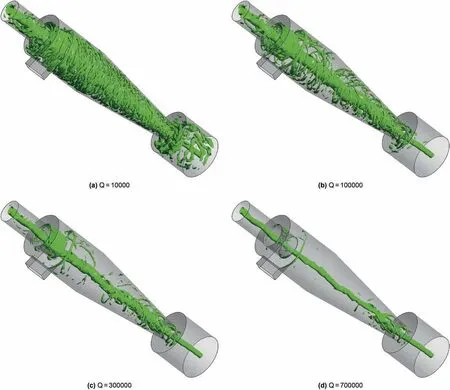
Fig.10.Three-dimensional iso-vortex surfaces of different values of Q.
At present,scholars have put forward many advanced technologies (Sengupta et al.2012,2013,2018,2019) to study the flow field.However,due to the limitations of conditions,many have not been applied in practice.Since the rotating flow in cyclone separator was strong,we used the Q criterion defined by Hunt et al.,(1988) to identify the vortex structure.The calculation equations are:

According to these above formulas,the iso-vortex surface was made.Fig.10 shows three-dimensional iso-vortex surfaces of different values of Q.The distortion degree of iso-vortex surface reflects the intensity of turbulence.The greater the distortion,the stronger the turbulence.The equivalent diameter of iso-vortex surface indicated the intensity of flow motion.We know that the turbulence above the dust hopper was strong from Fig.10(d).The increase of turbulence intensity would aggravate the backmixing of particles above the dust hopper and reduce the separation efficiency.
The flow pattern become more complex due to the backflow of airflow when the flow was close to the cone section,resulting in certain fluctuations.From one perspective,the micro vortex on the sidewall would prolong the residence time and increase the separation efficiency for the particles with a smaller diameter.From another perspective,the energy given by the micro vortex would cause particles to rotate in the longitudinal direction,resulting in particles loss such as escape from the vortex finder.Due to the twist of center vortex,the small-scale vortex nearby would swing with the vortex center.When the vortex center was far away from the wall,the small-scale vortex of natural sidewall received the centripetal effect,and the eccentric area would be further expanded.
3.6.2.Comprehensive analysis of the vortex motion and the flow field
The vortex motion in cyclone separator plays a crucial role in understanding its operating process and separation performance.Fig.11 shows the comprehensive diagram of the iso-vortex surface and the velocity vector.The internal flow of cyclone separator belongs to the double-layer vortex structure of the outer vortex flow and the inner vortex flow.So,the tangential velocity is also divided into inner and outer double-layer vortex structure.We added some marking lines to the tangential velocity contour,as shown in Fig.11(b).The results showed that the position of marking lines was not axisymmetric.In this section,the velocity vector diagram(Fig.11(a)) and the iso-vortex surface (Fig.11(c)) were comprehensively analyzed,as shown in Fig.11(d).In the area above the dust hopper,the iso-vortex surface was distorted or even broken.This phenomenon would cause kinetic energy loss.Moreover,there was a longitudinal circulation distribution in the bottom plate at the entrance,corresponding to Fig.9(c).
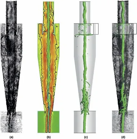
Fig.11.The comprehensive diagram of the iso-vortex surface and velocity vector.(a) The velocity vectors profile;(b) The tangential velocity contour;(c) The iso-vortex surface according to the Q criterion;(d) Comprehensive analysis diagram.

Fig.12.The local analysis near the entrance structure.
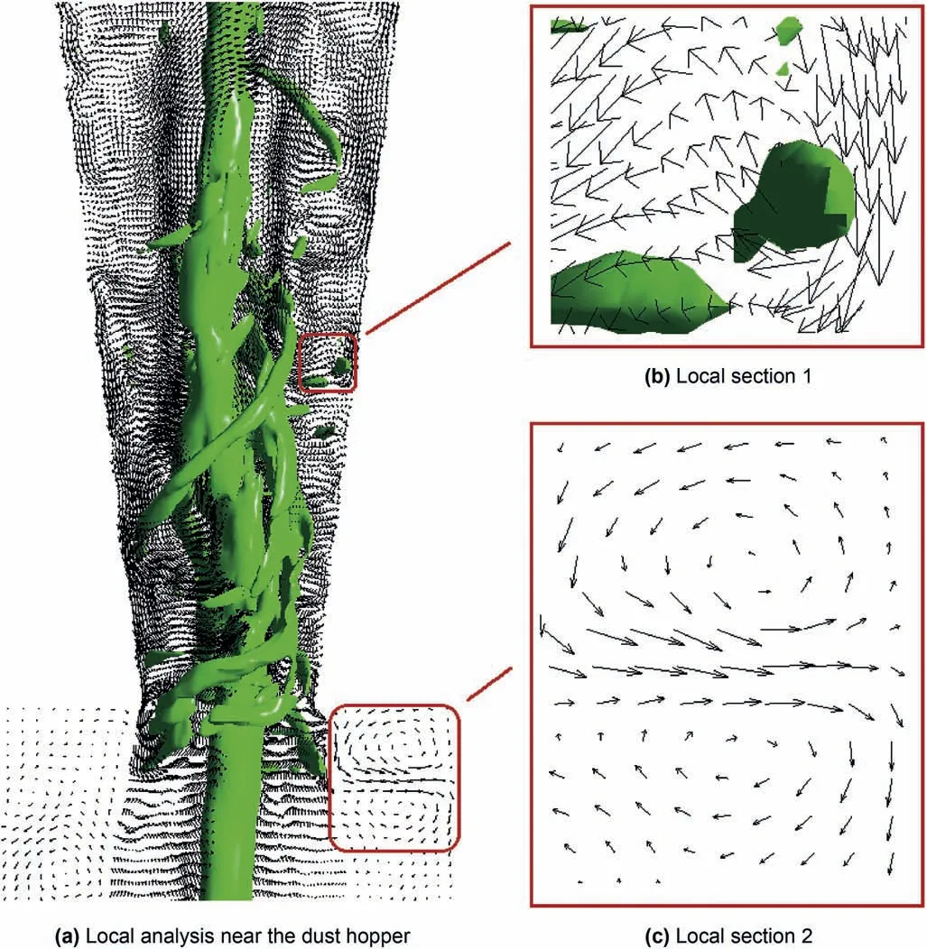
Fig.13.The local analysis near the dust hopper.
Here,we made a local analysis of the comprehensive diagram of iso-vortex surface and velocity vector.Fig.12(a) shows the local analysis near the entrance structure.It could be observed that there were many broken vortices,as shown green in Fig.12,which indicated that there has energy loss in the green display area.At the turning point of velocity vectors,vortices were formed and developed,as exhibited in Fig.12(b).The velocity vector would be distributed around a point,and the point was the center of the local vortex core,as illustrated in Fig.12(c).Moreover,the vortex would form an irregular annular region around the wall at the bottom of vortex finder,as exhibited in Fig.12(d).It reflected the vortex distribution of the longitudinal circulation.
Apart from the entrance region,the distribution of vortex motion above the dust hopper is also significant.This is another area needing to be analyzed and often discussed in the analysis of procession vortex core (PVC).Fig.13(a) shows the local analysis near the dust hopper.The results indicated that the vortex motion here was more complex,and the turbulence was strong.The vortex structure exhibited a strong distortion and broke into many small vortices.In addition,the velocity vector diagram formed many closed curves,as displayed in Fig.13(b).It indicated that many small vortices have been formed here and consumed energy.This region was also an area where the vortex oscillation was strong,corresponding to the eccentric circulation flow.Fig.13(c)shows the local velocity vectors profile of the dust hopper.There were two rotating flow in the opposite direction.It indicated that local turbulence was formed near the upper roof of dust hopper,which increased energy consumption.
4.Conclusions
Based on above mathematical analysis and numerical simulation,the main conclusions could be drawn as follows:
(1) According to the mathematical analysis,the kinetic energy dissipation rate of an incompressible fluid is directly related to the absolute value of vorticity in the fluid motion.In another words,the energy dissipation and flow characteristics of incompressible fluid are directly related to the vortex motion.
(2) At the turning point of velocity vector,vortices are formed and developed.These velocity vectors are distributed around a point,and the point is the center of the local vortex core.
(3) At the bottom of vortex finder,the vortex forms an irregular annular region around the wall,reflecting the vortex distribution of longitudinal circulation.
(4) The vortex motion near dust hopper is more complex,and the gas turbulence is strong.The vortex structure presents a strong distortion and breaks into many small vortices.This region is an area where the vortex oscillation is strong.Moreover,there are two rotating flow in the opposite direction within the dust hopper.
Sengupta et al.,2019
Acknowledgements
The authors gratefully acknowledge the support from and the Scientific Research Staring Foundation of Hainan University,No.KYQD(ZR)20042,Young Talents' Science and Technology Innovation Project of Hainan Association for Science and Technology,No.QCXM202027,and supported by Hainan Provincial Natural Science Foundation of China,No.520QN228.
- Petroleum Science的其它文章
- Retraction notice to“Interactions of ferro-nanoparticles(hematite and magnetite) with reservoir sandstone:Implications for surface adsorption and interfacial tension reduction”[Petrol.Sci 17 (2020)1037-1055]
- Carbon nanotube enhanced water-based drilling fluid for high temperature and high salinity deep resource development
- Impacts of inorganic salts ions on the polar components desorption efficiency from tight sandstone:A molecular dynamics simulation and QCM-D study
- Application of nanomaterial for enhanced oil recovery
- New insights into the mechanism of surfactant enhanced oil recovery:Micellar solubilization and in-situ emulsification
- Ce2(MoO4)3 as an efficient catalyst for aerobic oxidative desulfurization of fuels