Various concentric-ring patterns formed in a water-anode glow discharge operated at atmospheric pressure
Kaiyue WU (吴凯玥), Na ZHAO (赵娜), Qiming NIU (牛齐明),Jiacun WU (武珈存), Shuai ZHOU (周帅), Pengying JIA (贾鹏英) and Xuechen LI (李雪辰),*
1 Institute of Life Science and Green Development,Hebei University, Baoding 071000,People’s Republic of China
2 School of Mathematics and Physics, Handan University, Handan 056005, People’s Republic of China
3 College of Physics Science and Technology,Hebei University,Baoding 071000,People’s Republic of China
Abstract Pattern formation is a very interesting phenomenon formed above a water anode in atmospheric pressure glow discharge.Up to now,concentric-ring patterns only less than four rings have been observed in experiments.In this work,atmospheric pressure glow discharge above a water anode is conducted to produce diversified concentric-ring patterns.Results indicate that as time elapses,the number of concentric rings increases continuously and up to five rings have been found in the concentric-ring patterns.Moreover, the ring number increases continuously with increasing discharge current.The electrical conductivity of the anode plays an important role in the transition of the concentric patterns due to its positive relation with ionic strength.Hence, the electrical conductivity of the water anode is investigated as a function of time and discharge current.From optical emission spectrum,gas temperature and intensity ratio related with density and temperature of electron have been calculated.The various concentric-ring patterns mentioned above have been simulated at last with an autocatalytic reaction model.
Keywords:atmospheric pressure glow discharge,pattern formation,water anode,concentric-ring pattern, autocatalytic reaction model
1.Introduction
Water-electrode discharges can normally operate at atmospheric pressure and at a glow discharge mode [1], because the water electrode limits discharge current, and water evaporation has a cooling effect[2].They are attracting more and more attentions due to abundance in reactive oxygen and nitrogen species[2,3].Accordingly, water-electrode glow discharges at atmospheric pressure have broad potentials in diversified application fields,including water purification and activation[4-8],nanomaterials synthesis [9, 10], catalysis [11, 12], and medicine [13, 14].
The plasma attachment to a water electrode is apt to be uniform, presenting a disk shape in the interface between the glow plasma and the water electrode [15].Other than the uniform disk,some discrete spots can also be formed above a water electrode [16].Under proper conditions, some self-organized patterns appear, especially above a water anode [17, 18].A single ring is formed if the electrical conductivity of water anode is higher than 17.3 μS·cm-1[19, 20].The single ring is attributed to the distinctive rotating motion of a micro-discharge channel, resulting from the generated electronegative species during the discharge that poison the discharge[21].Diameter of the single ring increases until reaching a maximum, and then decreases with the increase of discharge current [18].Besides,the single-ring pattern varies and may transit to other discharge patterns with adjusting gas flow rate,discharge current,and gap width [22].Although various parameters can affect pattern transitions,the determining factor is related to electrode and gas temperatures[22].In fact,the formation mechanism of pattern is still not understood very well [23].With a reaction-diffusion mechanism, patterns above a water anode are initiated with an autocatalytic reaction of electrons, which is dictated by discharge current and ionic strength [24].
More complex ring patterns have been observed above a water anode.For example, a double-ring pattern is formed with 1.0%NaCl solution used as a water anode[25].Excited by an alternating-current(AC)sinusoidal voltage,the doublering pattern has also been found under a low conductivity of 55 nS·cm-1[26].Compared to the double ring, a triple-ring pattern is only formed with a conductivity higher than several hundred μS·cm-1, which can be excited by a direct-current(DC)voltage[27],an asymmetric sine[28],or a square wave[29].Up to now,concentric-ring patterns more than quadruple rings have not been reported in the literature.
In this work,concentric-ring patterns up to five rings are formed in the interface between the water anode and the glow discharge plasma.The ring number of the concentric-ring patterns increases with increasing ionic strength (electrical conductivity) and discharge current.These concentric-ring patterns are numerically reproduced based on the model of the autocatalytic reaction.
2.Experimental setup
As shown in figure 1, a 3.0 mm diameter rod is made from tungsten, which has a flat end.The rod electrode is placed above a glass reservoir,which has a diameter(inner diameter)of about 75 mm.The reservoir with a depth of 75 mm is full of water,whose initial electrical conductivity is 330 μS·cm-1.The electrical conductivity of the water anode is measured by a conductivity tester (Inesa DDSJ-308F).The water reservoir is cooled by being placed in a water tank at a constant temperature of about 25 °C.Water in the reservoir serves as the anode through electrical ground via an immersed metal mesh, and the rod acts as the cathode through being connected to a DC power source (Glassman EK15R40).In the circuit, a ballast resistor (R = 50 kΩ) is used to restrict the discharge current.The gap width (d) is 5.0 mm.The gas discharge in the gap is carried out in atmospheric environment.Hence, the working gas is room air at a pressure of 1.013×10⁵Pa, with a temperature of 300 K and a humidity of 35%.A single-lens-reflex camera (Canon EOS 5D Mark IV)with variable exposure time(texp)is used to obtain wateranode discharge patterns at an oblique angle (45°).After being focused by a lens, light emission is transmitted by an optical fiber into the entrance slit of a spectrometer (PI ACTON SP2750)with a grating of 2400 grooves mm-1,thus optical emission spectrum can be collected.A voltage probe(Tektronix P6015A) is used to detect applied voltage (Va),and a current coil (Pearson 8600) is employed to measure discharge current(I).Waveforms of Vaand I are monitored by a digital oscilloscope (Tektronix DPO4104).Typical waveforms of Vaand I are presented in figure 1(b).It can be seen that no pulse can be found in Vaand I, which means that the discharge operates in a continuous mode.

Figure 1.(a) Schematic diagram of the experimental setup.(b) Waveforms of applied voltage (Va) and discharge current.
3.Results and discussion
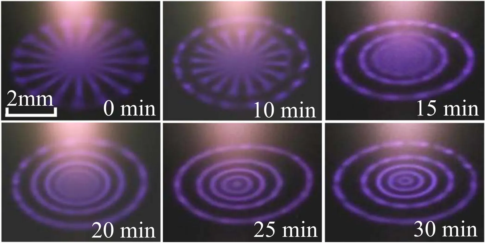
After atmospheric pressure glow discharge is initiated in the air gap, a radial-stripe pattern is formed at once above the water anode with I of 30.0 mA,as illustrated in figure 2.The radial-stripe pattern is surrounded by a ring as time elapses,leading to a single-ring pattern at 10 min.The ring number continuously increases from 15 to 25 min.That is to say, the concentric-ring pattern undergoes a scenario from a double ring (15 min), a triple ring (20 min), to a quadruple ring(25 min).For these concentric-ring patterns, the center is luminous.At last(30 min),a quintuple ring is time-invariantly stabilized above the water anode.Different to other concentric-ring patterns, the quintuple-ring pattern has a dark center.In a word, the ring number of the concentric-ring patterns increases with time elapsing, and up to five rings have been observed under the constant current of 30.0 mA.It is the first time that the quadruple-ring and the quintuple-ring patterns are observed in atmospheric pressure water-anode glow discharge.

Figure 2.Temporal evolution of self-organized patterns on the water surface(initiation moment corresponds to 0 min).Discharge current is 30 mA, gap width is 5.0 mm, and texp is 10 ms.

Figure 3.Transition of the time-invariant patterns with increasing discharge current.Gap width is 5.0 mm, and texp is 100 ms.

Figure 4.Average conductivity of the water anode as a function of operation time (a) and discharge current (b).
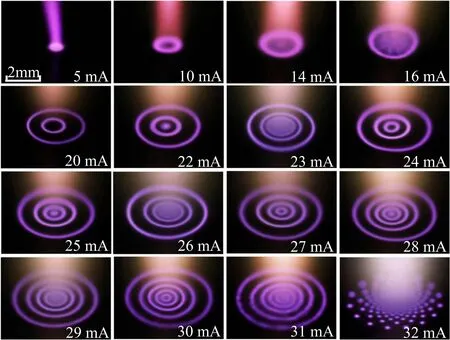
As mentioned above, pattern becomes time-invariant after about half an hour operation of the discharge.However,the final time-invariant pattern evolves with varying discharge current, as presented in figure 3.At a low discharge current(5.0 mA), the pattern seems like a diffuse spot.Its diameter slightly increases with increasing discharge current.With a current of 10.0 mA,the diffuse-spot pattern transits to a single ring (the center is dark), which is similar to that reported by Shirai et al [30, 31].When discharge current is increased to 14.0 mA,a diffuse spot appears in the center of the single-ring pattern.The diameter of the single ring increases and the central spot grows as discharge current is further elevated(16.0 mA).When discharge current reaches 20.0 mA, the central spot evolves into a new ring,resulting in a double-ring pattern.In a word,it seems that as discharge current increases,newcomer tends to appear in the center,which then transits to a new ring under a proper current.Interestingly, the pattern obeys this rule with further increasing discharge current, as can be seen for the transitions from the double-ring pattern(20.0 mA) to the triple ring (24.0 mA), from the triple-ring pattern (25.0 mA) to the quadruple ring (27.0 mA), and from the quadruple ring(28.0 mA)to the quintuple ring(30.0 mA).During these transitions, the ring number increases with increasing discharge current.Up to five concentric rings have been formed, and there is a central spot in the center of the quintuple ring at 31.0 mA.With further increasing discharge current, the concentric-ring patterns cannot be sustained above the water surface, and some discrete spots can be seen above the water anode (32.0 mA).
Electronegative species generated in the discharge, such as O, O3, H, OH, NO, NO2, NO3, NH, and NH2, can attach free electrons [21].Resultantly, negative ions, mainly O-,H-, OH-, NO-, etc, will be deposited on the water surface[15, 32].The deposited negative ions enhance the electric field in the interface between the bulk plasma and the water anode, resulting in a layer near the water surface, which is brighter than the plasma above it [15, 33].When these negative ions are distributed nonuniformly, the region with more negative ions is brighter due to a higher enhanced field.In the bulk plasma, electrons are mainly produced near the axis of the discharge due to the high α (the first Townsend ionization coefficient) resulting from the maximal electric field in the center.In turn, more electrons will generate more electronegative species near the discharge axis.After generation, electrons and electronegative species near the axis diffuse to the rim.Hence, compared with the discharge rim,more electrons and electronegative species are abundant in the center.As a result, more negative ions tend to be deposited above the central region of the pattern.Therefore,newcomer is inclined to appear in the center of the concentricring patterns with increasing current.

Figure 5.Optical emission spectrum scanned from 300 to 800 nm.
As pointed out by Rumbach P et al [24], ionic strength(IS) and discharge current (I) mutually dictate the autocatalytic reaction of electrons.Hence, ISand I should be responsible for the pattern evolution mentioned before.Between them, ISis positively related with electrical conductivity.Hence, the electrical conductivity of the water anode is studied, as indicated in figure 4.Resulting from the generation of HNO3and HNO2[34, 35], the conductivity of the water anode increases with time,which reaches saturation after about 30 min operation.Moreover, the conductivity increases with increasing discharge current.In combination with figures 2 and 3, it can be deduced from figure 4 that pattern type varies with the variation of electrical conductivity(related with IS).
Figure 5 presents 300-800 nm scanned optical spectrum emitted from the discharge above the water anode.Besides the second positive system of N2(C3∏u→B3∏g)[32],spectral lines of Ar I(4p→4s)[36],and O I(3p3P → 3s3S)at 844 nm[37], the first negative system ofsystem band from OH(A2∑+→ X2∏) [38], NH(A3∏→X3∑) [39], and NO(A2∑+→ X2∏)[26],can also be discerned.From optical emission spectrum,intensity ratio of spectral lines(391.4 nm to 380.5 nm, and 371.1 nm to 380.5 nm) has been investigated, as presented in figure 6.The line intensity ratio of 391.4-380.5 nm is an indicator to electron temperature (Te),while that of 371.1-to 380.5 nm can reflect the variation trend of electron density(ne)[40,41].Results show that both Teand neincrease as time elapses or current increases.In addition, gas temperature (Tg) has been estimated from the first negative system ofthrough using LIFBASE software[42].Obviously, as time elapses, Tgkeeps increasing until reaching a constant value after 30 min discharge operation.Tgalso increases with increasing current.As is well known[22], Tghas a decisive effect on the pattern structure.Therefore, the concentric-ring pattern transits concurrently with Tgvariation.

Figure 6.Intensity ratio and gas temperature as functions of operation time and discharge current.
The aforementioned concentric-ring patterns are simulated by the same method explored by Rumbach P et al[24].From the Turing reaction-diffusion mechanism [43], it is believed that electrons are used as activators.Through the collision ionization of electrons, the autocatalytic reaction is realized, which is dictated by discharge current (I) and ionic strength(IS).With this model,the discharge patterns are given by the eigenfunctions(harmonics)of the cylindrical Laplacian(Ylmn) as follows, and detailed derivative process of the cylindrical Laplacian can be found in the[24].Here,l,m,and n are positive integers

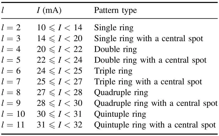
where Jm(kmlr) corresponds to the mth Bessel function of the first kind.(r,z,θ)are cylindrical coordinates.kml=a ml/rp(rpis the finite radius of the plasma), where amlcorresponds to the lth zero of the mth Bessel function.Amland Bmlare undetermined coefficients, andk nz=π/2 for simplicity.According to the formula, the cylindrical harmonics (the simulated patterns) are obtained with m = 0, as shown in figure 7.With l = 2 and m = 0, the simulated pattern is the single ring with a dark center (hollow structure).A central spot appears in the single ring with l = 3 and m = 0.With increasing l,the simulated concentric-ring patterns increase in ring number.
The relationship between the l value and discharge current is listed in table 1.From table 1,one can see that the integer(l)increases with increasing discharge current.However, discharge current has a small variation range for a specific l value.Hence, all of the concentric-ring patterns formed in experiments have been numerically reproduced in simulations.However, at most five rings have been observed in experiments, which transit to discrete spots with current higher than 32 mA.This can be explained from the criteria for stability,which is related with the first Townsend ionization coefficient(α)[24].α in the interfacial layer between the bulk plasma and the water anode is influenced by Tg.With a current higher than 32 mA, Tgis so high that stability criteria cannot be satisfied any more,resulting in the disappearance of the concentric-ring patterns.As a result, at most five concentric rings have been observed in our experiment.However,the maximal number of concentric rings is not limited according to formula(1).Hence,we believe that more rings could be obtained if the onset of thermal instability are restrained.Therefore, we will try our best to reduce the gas temperature in our future work through the usage of liquid nitrogen as a refrigerant, similar to that reported in the [44-46].

Figure 7.The concentric-ring patterns given by the cylindrical Laplacian equation where k nz =π/2.

Table 1.The relationship between the l value and the discharge current (I).
4.Conclusion
In summary, various concentric-ring patterns have been formed above the water anode of a glow discharge operated in atmospheric pressure air.The results reveal that the ring number of the patterns increases with time elapsing.Moreover, it increases with increasing discharge current.Among these concentric-ring patterns, it is the first time that the quadruple-ring and the quintuple-ring patterns are observed in water-anode glow discharge operated in atmospheric pressure air.For both the quadruple ring and the quintuple ring, the center is either luminous or dark,depending on the discharge current.It has been found that the electrical conductivity of the water anode, electron temperature, electron density, and gas temperature vary as a function of time elapses and increasing discharge current.At last, the various concentricring patterns are reproduced in simulations based on the autocatalytic reaction model dictated by ionic strength and discharge current.
Acknowledgments
This work is financially supported by National Natural Science Foundation of China (Nos.11875121 and 51977057),Natural Science Interdisciplinary Research Program of Hebei University(Nos.DXK201908 and DXK202011),and Natural Science Foundation of Hebei Province, China (Nos.A2020201025 and A2019201100).In addition,we appreciate the financial support from Post-Graduate’s Innovation Fund Project of Hebei Province (Nos.CXZZBS2019023 and CXZZBS2019029), and Post-Graduate’s Innovation Fund Project of Hebei University (Nos.HBU2021ss063 and HBU2021bs011).
 Plasma Science and Technology2022年5期
- Plasma Science and Technology的其它文章
- Synthesis of Ag-decorated vertical graphene nanosheets and their electrocatalytic efficiencies
- Upgrade of an integrated Langmuir probe system on the closed divertor target plates in the HL-2A tokamak
- Numerical study of atmospheric-pressure argon plasma jet propagating into ambient nitrogen
- Effects of O2 addition on the plasma uniformity and reactivity of Ar DBD excited by ns pulsed and AC power supplies
- Design and first result of combined Langmuir-magnetic probe on J-TEXT tokamak
- Selective catalytic reduction of NOx with NH3 assisted by non-thermal plasma over CeMnZrOx@TiO2 core-shell catalyst
