Blast responses of polyurea retrofitted utility tunnel reinforced with basalt fibre reinforced polymer bars
Jian-nan Zhou, Xiao-shuo Chen, Yin-zhi Zhou, Wen-ye Wang, Peng Wang, Xin-li Kong,Ying Xu, Han-sheng Geng, Feng-nian Jin
State Key Laboratory for Disaster Prevention & Mitigation of Explosion & Impact, Army Engineering University of PLA, Nanjing, 210007, China
Keywords:Urban utility tunnel Retrofitting Polyurea CFRP Explosion
ABSTRACT Polyurea coating and carbon fibre reinforced polymer reinforcing techniques were applied to retrofit a severely damaged urban utility tunnel (UUT).The blast responses of the retrofitted UUT were investigated through in-filed explosion experimental tests, and the displacements, strains, accelerations, and damage were compared.The retrofitted UUT exhibited comparable or even better blast resistance than the intact UUT.Although the polyurea coating was flexible, it exhibited excellent performance in improving the blast resistance of the damaged UUT.As the UUT reinforced with basalt fibre reinforce polymer (BFRP) bars has smaller damage compared with the UUT reinforced with steel bars, its retrofitting is simple, and the cost is low.The roof was simplified as an elastically simple support one-way slab.Euler beam theory was adopted to analyse the dynamic responses of UUT roof considering the interaction between soil and structure, which agree well with the experiments in the first three cases.
1.Introduction
Urban utility tunnels (UUTs) have been widely constructed in modern cities [1,2].These underground tunnels can also serve as protective structures during accidental explosions,terrorist attacks,or even wartime [3,4].UUTs may be subjected to explosive loads,which is usually ignored during its design and construction.
In previous studies, many studies about the blast responses of UUT were conducted by Finite Element method[5,6].Zong et al.[7]investigated the blast performance of shallow buried utility tunnel subjected to ground surface explosion with small scaled distance by Finite Element method.De et al.[8] used geofoam barrier as protection against surface blast on underground tunnels by numerical modelling.Yang et al.[9,10]investigated the dynamic responses of metro tunnel in soft soil and shallow buried water diversion box culverts subjected to ground explosion by Finite Element method.
As blast experiments on large scale underground UUT are very expensive and time-consuming,there is quite limited literature on the experimental data of dynamic response of UUT under blast loading.Hayes et al.[11] obtained buried structures response behaviours in various backfill materials by series explosion tests.Ma et al.[12] investigated in-structure shock of underground shallow buried tunnel under ground shocks with both experimental and theoretical method.Zhou et al.[3,4] investigated the dynamic responses and failures of UUTs under repetitive surface explosions and revealed the potential damage patterns of blast-loaded UUTs.
In modern underground construction, fibre reinforced polymer(FRP) bars have been applied to reinforced concrete elements to improve their anti-corrosion ability [13-15].FRP-reinforced concrete elements always have a higher load-carrying capacity than steel-reinforced concrete elements [16-18] with identical reinforcement ratios.FRP-reinforced concrete structures also exhibit excellent blast-resistant ability[16-18].Zhou et al.[19]developed an improved finite difference method of predicting the dynamic response of blast-loaded FRP-reinforced concrete elements.Concrete elements are severely damaged during explosions [20,21].The FRP strengthening method has also been applied to retrofit damaged underground concrete elements [22,23] and efficiently improve the structural performance under explosion loads.
Polyurea coating is another retrofitting method used for strengthening anti-blast concrete elements[24,25].Chen et al.[24]found that compared to carbon FRP (CFRP) -strengthened panels,polyurea-coated panels possess a lower quasi-static load-carrying capacity but significantly higher blast-resistant ability.
In this study, the polyurea coating was applied to retrofit severely damaged UUTs,and the retrofitting effect was investigated through experimental explosion tests and comparisons with the CFRP strengthening technique.
2.Damaged UUT and retrofitting methods
2.1.Damaged UUT
The basalt FRP(BFRP)bar-reinforced UUT(BBRU)was subjected to repetitive explosions ranging from 1.5 to 0.7 m/kg[3].The unstrengthened UUT was 5200 mm long, 1740 mm wide, and 1740 mm high (Fig.1(a)).The thickness of the roof and side walls was 120 mm,and the concrete grade of UUT was C40.Details of the reinforcements were described by Zhou et al.[3,4].After nine explosions,the cover of the UUT was removed to examine the exterior damage.The final damage pattern was the extension of developed cracks along the UUT.Five parallel cracks were formed inside the UUT after repetitive explosions (Fig.1(a)).The maximum width of the cracks was approximately 1 mm.No cracks appeared on the outer surface of the UUT.
2.2.Retrofitting methods
Two retrofitting techniques were applied to strengthen the damage UUT and ensure that the damaged BBRU could be reused.Half of the UUT was strengthened with three CFRP cloth layers,and the other half was coated with 6 mm thick polyurea(Fig.1(b)).After retrofitting, the UUT was shallow-buried again for explosion tests(Fig.1(c)).
During retrofitting, SPE-120b-sprayed polyurea manufactured by Shjiazhuang Weishiqi New Material Co., Ltd.was applied.The carbon fibre cloth had an areal density of 300 g/mand a thickness of 0.167 mm;it was produced by Nanjing Mankate Technology Co.,Ltd.
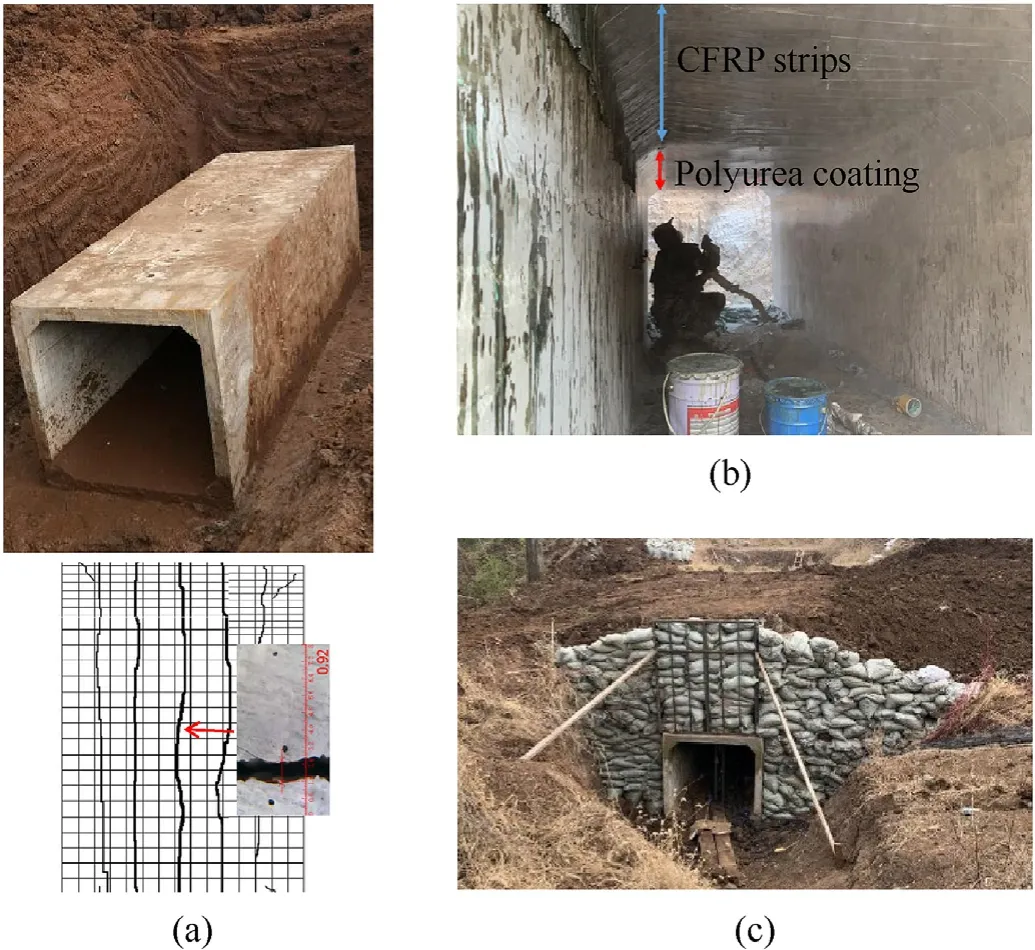
Fig.1.(a) Damaged UUT [3], (b) retrofitted UUT using polyurea coating and CFRP strips, and (c) shallow-buried retrofitted UUT for explosion.
2.3.Material properties
The material properties of the polyurea and CFRP cloth were first determined.The quasi-static tensile experiments were conducted to detect the material properties.The bone-like samples of polyurea and CFRP strips samples were shown in Fig.2 and Fig.4(a),respectively.The cross-section size of polyurea samples and CFRP strips samples were listed in Table 1.
The tensile stress-strain curves of polyurea were shown in Fig.3.The initial elastic modulus was only approximately 30 MPa,whereas the stress at this stage was lower than 3 MPa.The polyurea samples exhibited non-linear and large deformations.The fracture strain exceeded 2.0, and the fracture strength was higher than 150 MPa.
The stress-strain curves of CFRP strips were plotted in Fig.4(b).In contrast to the polyurea samples,the CFRP samples experienced brittle deformation (Fig.4(c)).The fracture strain was approximately 0.016, and the fracture strength value was close to 2500 MPa.
The material properties of polyurea and CFRP strips were listed in Table 1.Based on the experimental results, the materials could exhibit completely different behaviours.The CFRP cloth was stiff,strong, and brittle, whereas the polyurea was flexible and ductile.Thus, the two materials exhibited different explosive mechanical behaviours.
3.Explosion experimental tests
In-field explosion tests were performed to evaluate the retrofitting efficiency.The buried depth of the UUT was changed from 2 to 1.2 m to determine the designed scaled distance.The backfill soil above the top of the entrance was blocked using sandbags.The explosion scheme and measurement system are depicted in Fig.5.The Donghua test system was adopted to collect experimental data.Data acquisition instruments were connected through four-core shielding wires inside the tunnel to ensure the stability of the signal transmission.
The TNT block was placed above the central tunnel surface(Fig.6(a)).The pressures from the blast waves acting on the BBRU roof were measured using CYG1711F surface reflection pressure sensors(Fig.6(b)).The frequency response ranged from 0 to 20 kHz.The measurement range was 30 MPa,and the protection class was IP67.
The displacements of the roof and side walls were measured using PBS2C-200 displacement sensors with a frequency response of 0-40 kHz and a measurement range of 200 mm (Fig.6(c)).The strains of the polyurea coating and the CFRP cloth were measured using THY120-5AA(15%)-Q30P2K large-range strain gauges with a strain limit of 15% (Fig.6(d)).Acceleration sensors of type 350C03 were set up to obtain the acceleration values of the roof and side walls.
Details of the sensor locations are depicted in Fig.7.
Nine cases of experimental explosion tests were performed at a scaled distance changing from 2.0 to 0.557 m/kg(Table 2).In each case,the pressures, displacements,strains, accelerations,and damage patterns were recorded.
4.Explosion responses
4.1.Pressure analyses
Fig.8 shows two time-history curves for the pressure at the centre of the roof(P7)in Cases B7 and B8.The peak pressures from B1 to B9 are listed in Table 3,and these results were compared with the values obtained through CONWEP calculations.The results are consistent with acceptable errors, indicating that the measured pressures are reliable.These values are also close to those measured by Zhou et al.[3,4],guaranteeing latter comparisons under similar explosion conditions.
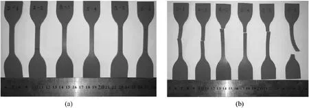
Fig.2.(a) Stretched and (b) broken polyurea samples.

Table 1 Tensile experiments and results for polyurea and CFRP strips samples.
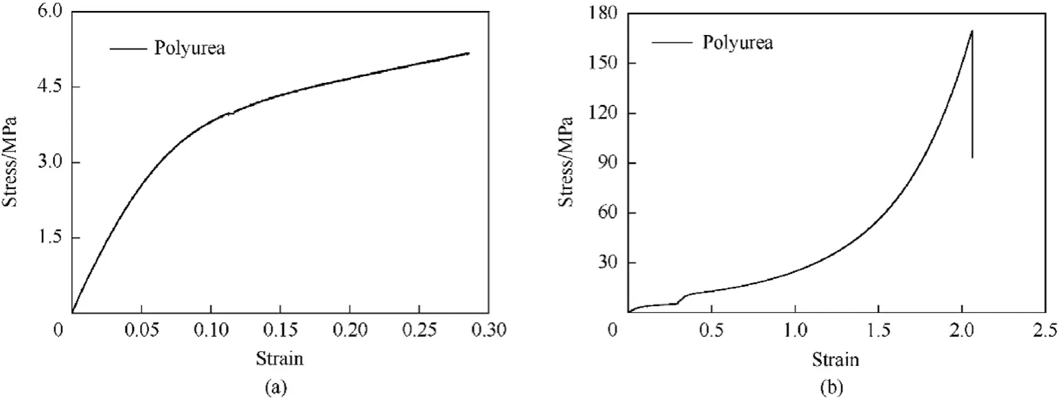
Fig.3.Tensile stress-strain curves for polyurea samples under (a) small deformation and (b) complete deformation.
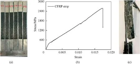
Fig.4.(a) CFRP samples, (b) tensile stress-strain curves, and (c) broken sample.
Fig.9 depicts the pressure distribution along the UUT.The inhomogeneity of the load distribution increased with the explosion load.The roof centre experienced more intense blast waves.
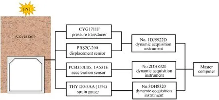
Fig.5.Explosion scheme and measurement system.
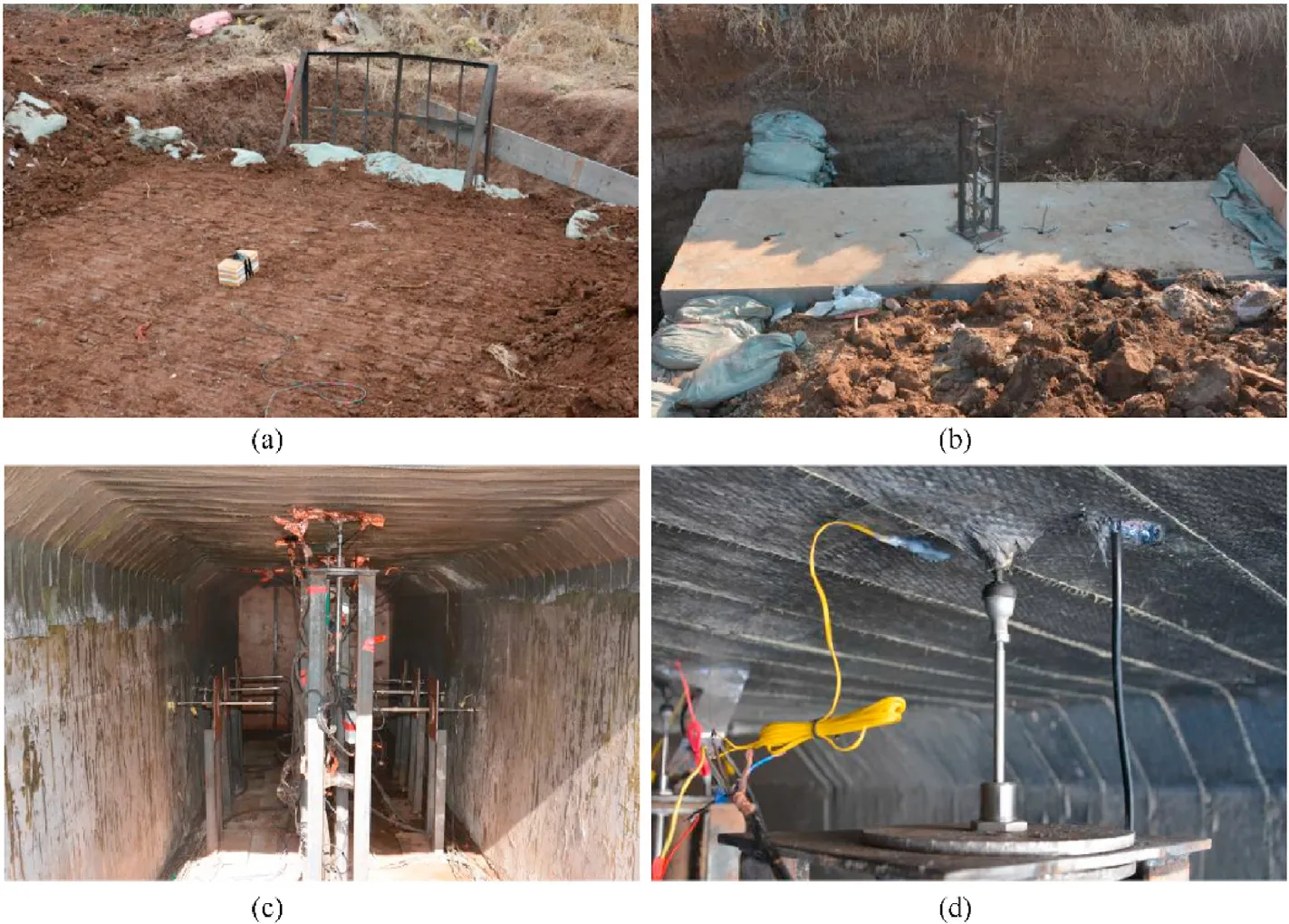
Fig.6.Explosion experiment: (a) TNT placement, (b) pressure sensor layout, (c) displacement sensor layout, and (d) strain sensor layout.
4.2.Displacement analyses
Because the displacement frames were fixed to the floor, all measured values were relative displacements with respect to the floor.Fig.10 shows the displacement curves for the roof.Points D2 and D3 were located at half strengthened with CFRP sheets, while Points D5 and D6 were located at half strengthened using polyurea coating.Point D4 was located at the centre of the roof.Measurement points D2 and D6 were symmetrical to the centre of the roof at 2.4 m.Points D3 and D5 were also symmetrical from 1.2 m.It was observed that a decrease in the scaled distance increased the deflection at each point (Table 4).The polyurea-coated segment had a slightly larger deflection from Cases B1 to B6 at an extended scaled distance.From Case B6 to B7,the scaled distance decreased,and the CFRP-strengthened segment experienced a slightly larger deflection.
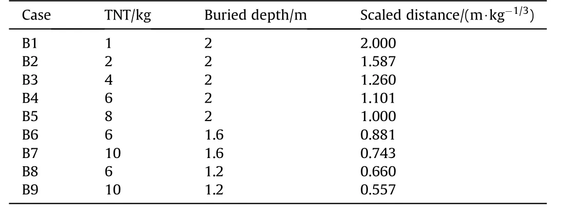
Table 2 In-field explosion cases.

Table 3 Measured and calculated peak pressures for each case (MPa).
The strengthening effect of the CFRP cloth was directly compared with that of the polyurea coating (Fig.11), and the displacement distributions along the UUT were recorded.
The displacements of the CFRP cloth-reinforced roof for cases B1 to B5 were smaller than those of other cases,and the strengthening efficiency of the CFRP cloth was better.When the scaled distance was 0.881 m/kg, the maximum displacement of the polyureareinforced side decreased.As the scaled distance decreased, the displacement difference between the two segments increased.The advantage of the polyurea coating in retrofitting was significant at a smaller scaled distance.It was observed that the CFRP cloth improved the retrofitting under a weak explosion load at a considerable scaled distance, whereas the polyurea coating performed better under intense explosion at a short-scaled distance.In this study, the critical scaled distance was 0.881 m/kg.
The measured data were compared with those of intact UUTs obtained by Zhou et al.[3,4] (Fig.12).
At the same scaled distance, the CFRP-strengthened UUT was significantly smaller (Fig.12(b)).The polyurea-coated UUT under intense explosion experienced a significantly smaller deflection(Fig.12(c)),and the retrofitting efficiency of the polyurea coating was validated.After strengthening,the displacement of the side wall was also smaller (Fig.12(d)).
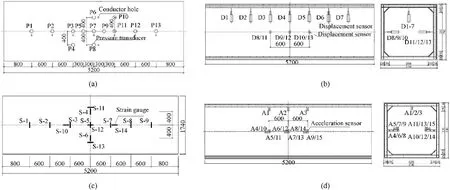
Fig.7.Locations of (a) pressure sensors, (b) displacement sensors, (c) strain sensors, and (d) acceleration sensors.
4.3.Strain analyses
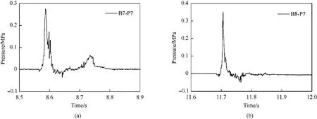
Fig.8.Typical blast pressure curves at (a) B7 and (b) B8.
The maximum strain values are listed in Table 5.At the same scaled distance, the polyurea coating experienced a larger strain than the CFRP cloth.The maximum strain of the polyurea coating experienced a displacement comparable to that of the unstrengthened UUT (Fig.12(a)).Under intense explosion, the displacement of the un-strengthened UUT was slightly large.The retrofitting efficiency of the CFRP cloth was validated.Moreover,the displacement of the strengthened UUT under intense explosion reached 17777.2 με, and that of the CFRP cloth was only 2157.8 με.As the CFRP cloth had a comparatively higher elastic modulus,the CFRP cloth exhibited a significantly smaller strain than the polyurea coating.

Table 4 Peak displacement at each measurement point (mm).
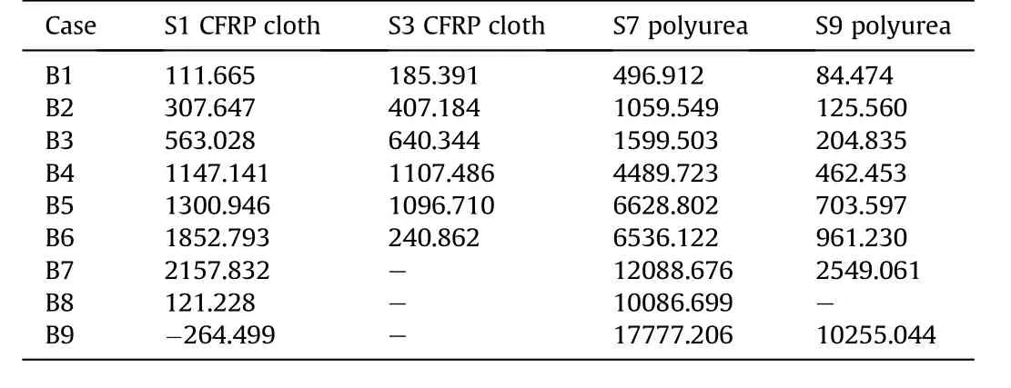
Table 5 Peak strain at each measurement point (με).

Table 6 Material property of UUT roof and reinforcing materials.
However, the variation in the strain with the scaled distance is interesting.The CFRP cloth strain initially increased with decreasing scaled distance and then abruptly decreased at Case B8 for Point S5,and at Case B6 for Point S3.On the contrary,the strain of the polyurea coating continuously increased with decreasing scaled distance.This trend indicates that the CFRP cloth will delaminate from the concrete and be subjected to minimal loads when the explosion is intense.The critical scaled distance in Case B6 was 0.881 m/kg.This phenomenon was similar to that of the displacement.
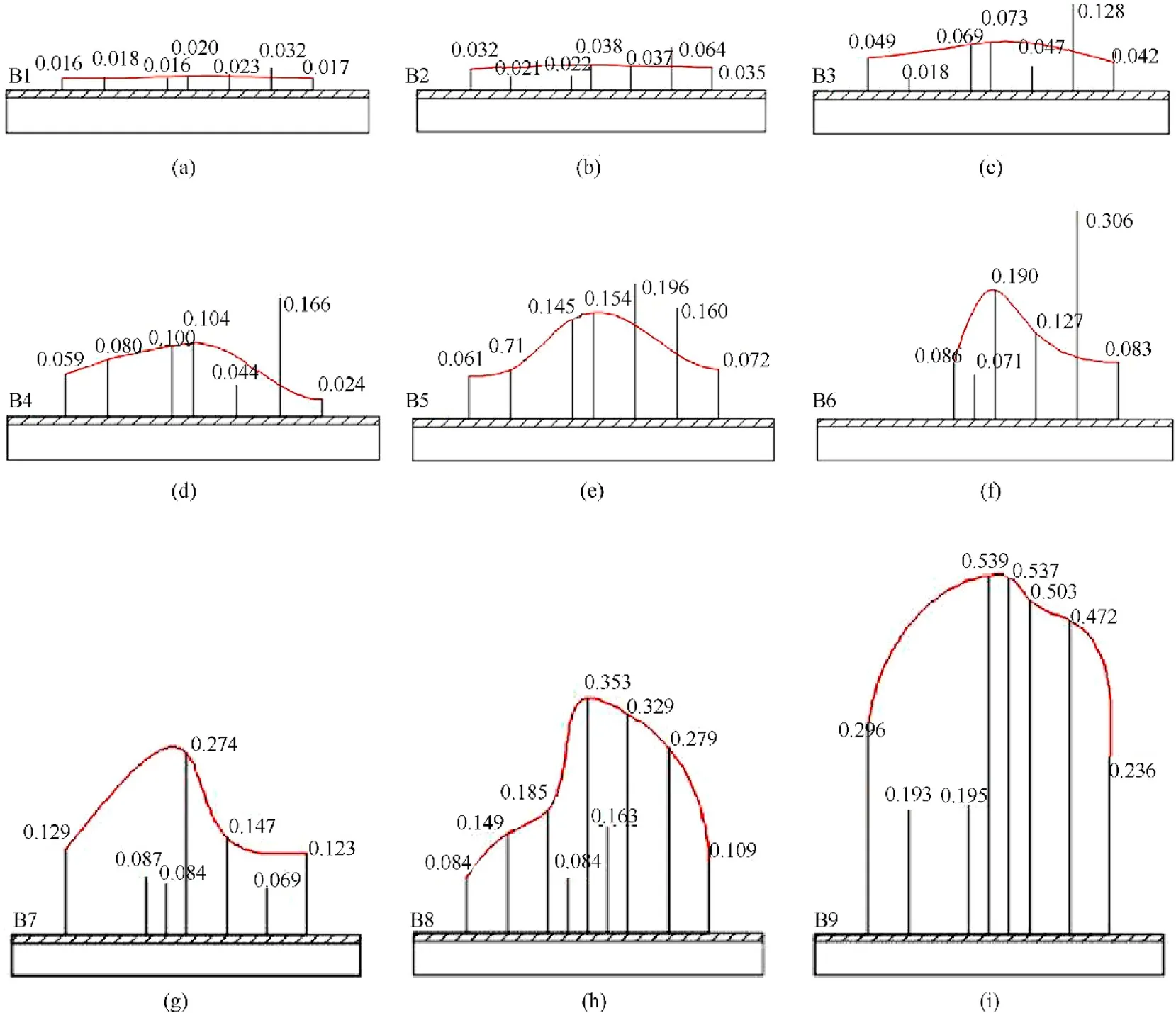
Fig.9.Pressure distribution along UUT in (a) B1, (b) B2, (c) B3, (d) B4, (e) B5, (f) B6, (g) B7, (h) B8, and (i) B9.
4.4.Acceleration analysis
Accelerations were measured and compared with those of unstrengthened BBRU specimens obtained by Zhou et al.[3,4](Fig.13).From Cases B1 to B5,the accelerations of the roof and side walls approximately increased inversely linear to the scaled distance.After Cases B6 and B7, the accelerations increased sharply.The accelerations significantly decreased after retrofitting, validating the strengthening effect.
4.5.Damage
After the explosion tests were conducted, the damage patterns of the roof were compared (Fig.14).No damage on the polyurea coating surface was observed, while local fracture and large-area delamination of the CFRP cloth from the concrete occurred.These phenomena provided a reasonable explanation for the large deflection of the CFRP cloth-strengthened segment under intense explosions, and the strain of the CFRP cloth abruptly decreased to nearly zero.Delamination of the CFRP cloth was the main reason for the larger deflection.The tight adhesive between the polyurea coating and the concrete facilitated the retrofitting effect under intense explosion loads.
5.Dynamic analyses
The dynamic response of UUT roof is theoretically analysed in this section.As the span-thickness ratio is exceed 60,the UUT roof can be simplified as Euler beam model in dynamic analyses.The interaction between soil and structure was considered by introducing interface damping.This method can rapidly predict the maximum displacement of UUT roof subjected to ground explosion and is helpful for UUT structural anti-blast design.
5.1.Blast loading
The blast loading at calculated section was simplified to uniformly distributed load along transverse direction.The blast loads at a given pointis calculated by the loads at central point of UUT roofmeasured in tests.The calculate method is given as Eq.(1).The calculation diagram was shown in Fig.15.

where,υ is poisson ration of reinforced concrete which is 0.3 in this project.φ is the angle between the roof centre,the given point and the explosion point.
As TM5-855-1[27],equivalent uniformly distributed load can be obtained by the mid-span loads.As the ratio of buried depth to short span of roof is 1.66, equivalent uniform coefficient is 0.88 in this project.
The ground shock reducing exponentially after reaching its peak pressure,as shown in Fig.16 of Actual pressure.The attenuation law is given as Eq.(2).
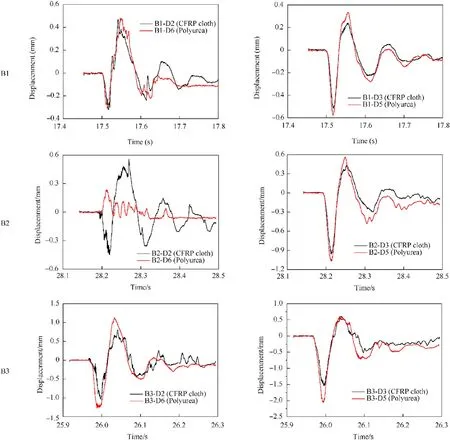
Fig.10.Displacement time-history curves for tunnel roof: (a) Roof D2 (CFRP) and D6 (Polyurea), and (b) Roof D3 (CFRP) and D5 (Polyurea).

where σis the maximum equivalent uniformly distributed load at given section with unit MPa.is the pressure rising time with unit s.is the time when the blast pressure reaches the calculated point.In this project,=10[27].
To simplify calculation, the blast pressure time history can be simplified as triangular blast loads with rising phrase and reducing phrase,as shown in Fig.16 of Simplified pressure.The expression of simplified curve can be given as Eq.(3).

whereis the time when pressure reducing from σto zero,which can be given as Eq.(4).

5.2.Analysis model
The dynamic response of UUT roof can be divided into three stages: pressure rising stage, pressure reducing stage and free vibration stage.The pressure rising stage and pressure reducing stage range from 0<≤0.05and 0.05<≤1.05,respectively.The dynamic governing equation on the cross section of UUT roof at the given point in pressure rising stage and pressure reducing stage are given as Eq.(5) and Eq.(6), respectively.

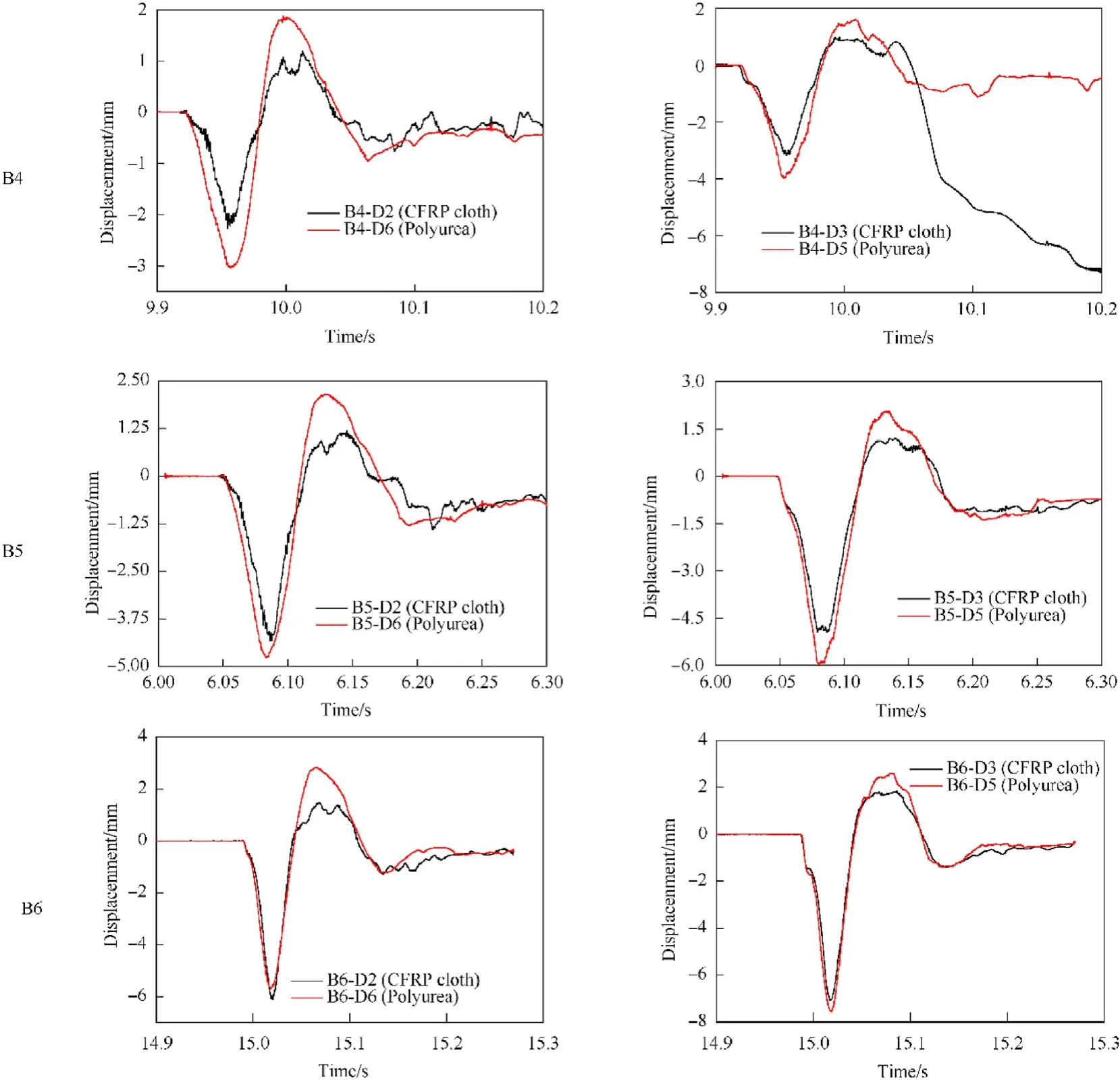
Fig.10.(continued).

where(,) is the displacement of roof, in whichis the coordinate of the given section., ρ andis flexural rigidity, density and section area of UUT roof.ρis wave impedance of backfill soil.
The displacementcan be calculated by Eq.(7)in elastic stage.

where,()is theth mode of the beam,and()is generalized coordinate.
Based on the elastic boundary conditions,W()can be given as Eq.(8).

Take Eq.(7)into Eq.(5),the governing equation can be given as Eq.(9).

where ωis theth natural frequency of beam given as Eq.(10).

Assuming that the interfacial damping between soil and structure is ξgiven as Eq.(11), Eq.(10) will be given as Eq.(12).

whereis the beam length.

ξ≥10<≤0.05
The initial conditions are(,0)=0 and ˙(,0) = 0.The solution of Eq.(12) is given by
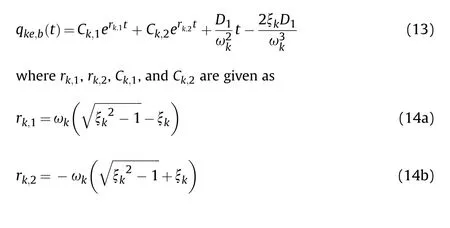

Combined with Eq.(8) and Eq.(10), the displacement atth mode is obtained as

ξ≥10.05<≤1.05
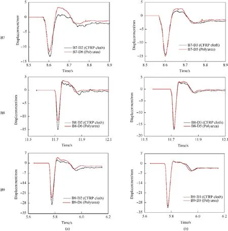
Fig.10.(continued).
In pressure reducing stage, the initial conditions were given in
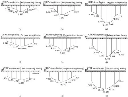
Fig.11.Flexural distribution maps of tunnel roof in (a) B1, (b) B2, (c) B3, (d) B4, (e) B5, (f) B6, (g) B7, (h) B8, and (i) B9.

Taking Eq.(16) into Eq.(12), the solution can be given as

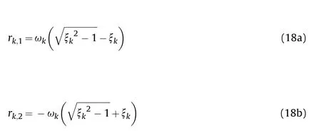
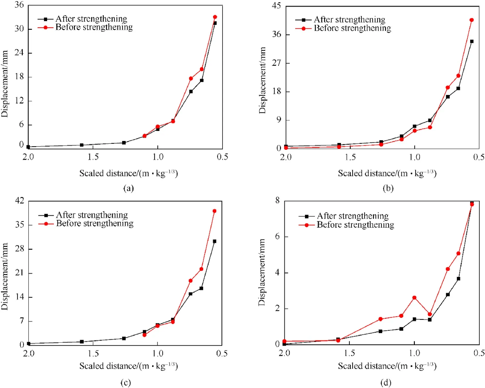
Fig.12.Displacement comparison between un-strengthened BBRU and retrofitted BBRU at (a) D3 strengthened using CFRP cloth, (b) roof centre D4, (c) D5 strengthened using polyurea coating, and (d) side wall centre D9.

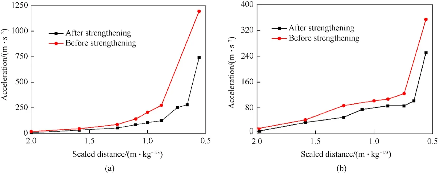
Fig.13.Comparisons of accelerations before and after retrofitting: (a) vertical acceleration of roof centre and (b) horizontal acceleration of side wall.

Fig.14.UUT roof after explosions: (a) undamaged polyurea coating, (b) CFRP cloth fracture, and (c) CFRP cloth delamination.
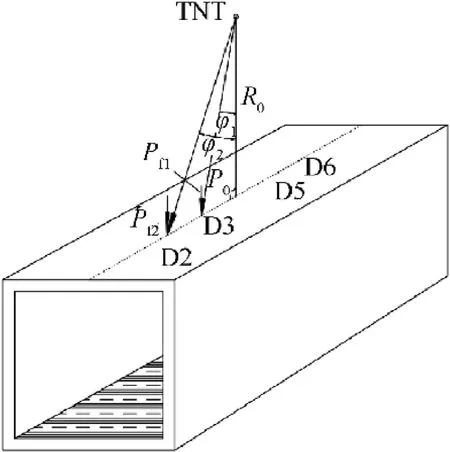
Fig.15.Calculation method of Blast loads in mid-span at a given point.
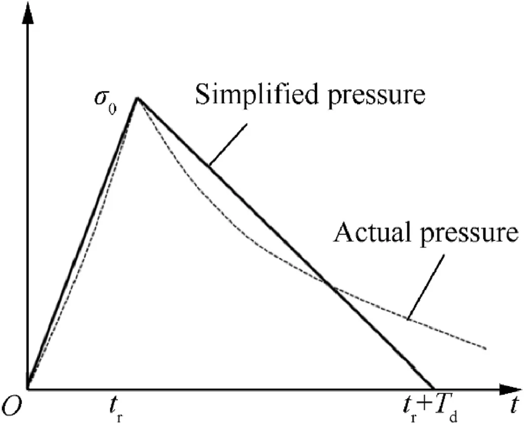
Fig.16.Blast pressure time history curve in soil.

The displacement atth mode is obtained as
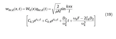
ξ<10<≤0.05
The calculate method in this case is similar to that in Case 1.The solution is given as

where,β, Cand Care given as
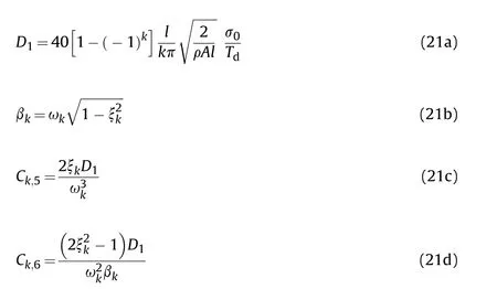
The displacement atth mode in this case is obtained as
ξ<10.05<≤1.05
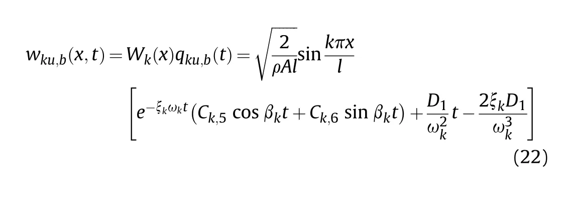
The calculate method in this case is similar to that of case 2.The solution of Eq.(12) in this case is given as

where,,β,andare obtained as
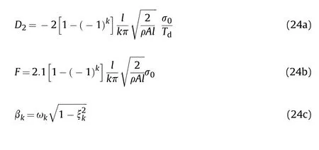
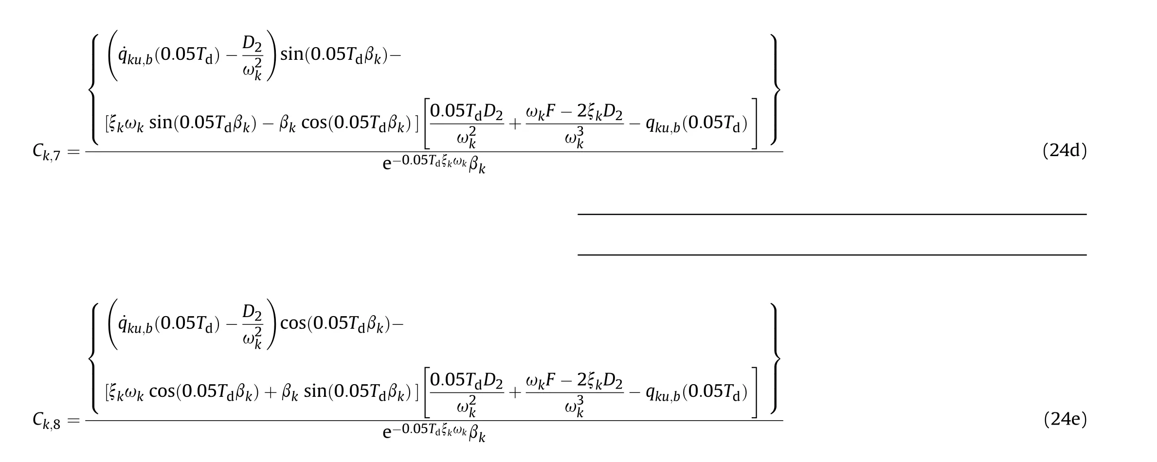
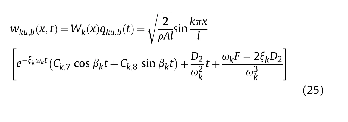
The displacement atth mode in this case is obtained as
>1.05T
In this case, UUT roof is in a state of free vibration.There is no interaction between soil and structure.The governing equation of roof can be given as

Considering that the response of roof is analysed in two situations of ξ≥1 and ξ<1 in the stage of forced vibration, the initial conditions of roof in free vibration stage is different in these two situations.
when ξ≥1, the solution of vibration coordinate is obtained as

whereandare given as
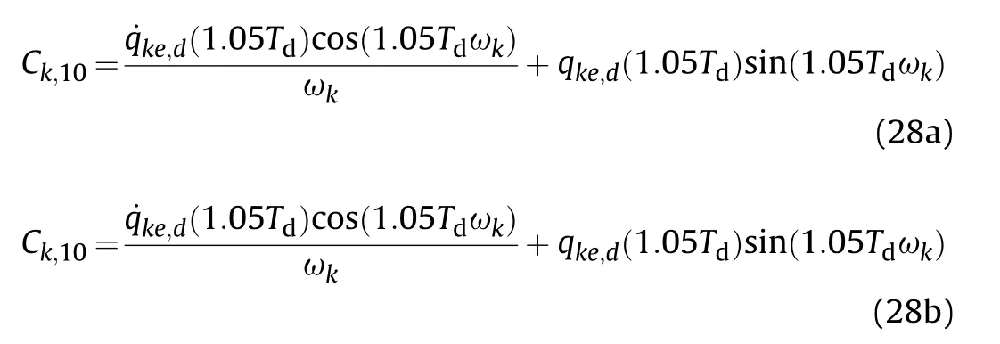
The displacement expression of roof is solutioned as
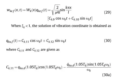

The displacement expression of roof is solutioned as

5.3.Validations
The elastic modulus of reinforced UUT roofcan be calculated by volume ratio of concrete and reinforcing materials, as given in Eq.(32).

whereandare the elastic modulus of reinforcing material and concrete,respectively.andare the volume ratio of reinforcing material and concrete, respectively.
The elastic modulus and volume ratio of concrete and reinforcing materials were listed in Table 6.According to Eq.(32), the equivalent modulus of elasticity of UUT roof repaired by Polyurea and CFRP cloth are 3.173 × 10MPa and 4.048 × 10MPa,respectively.
The parameters of reinforced UUT roof used in theoretical model were listed in Table 7.

Table 7 Parameters of UUT roof used in analyses.
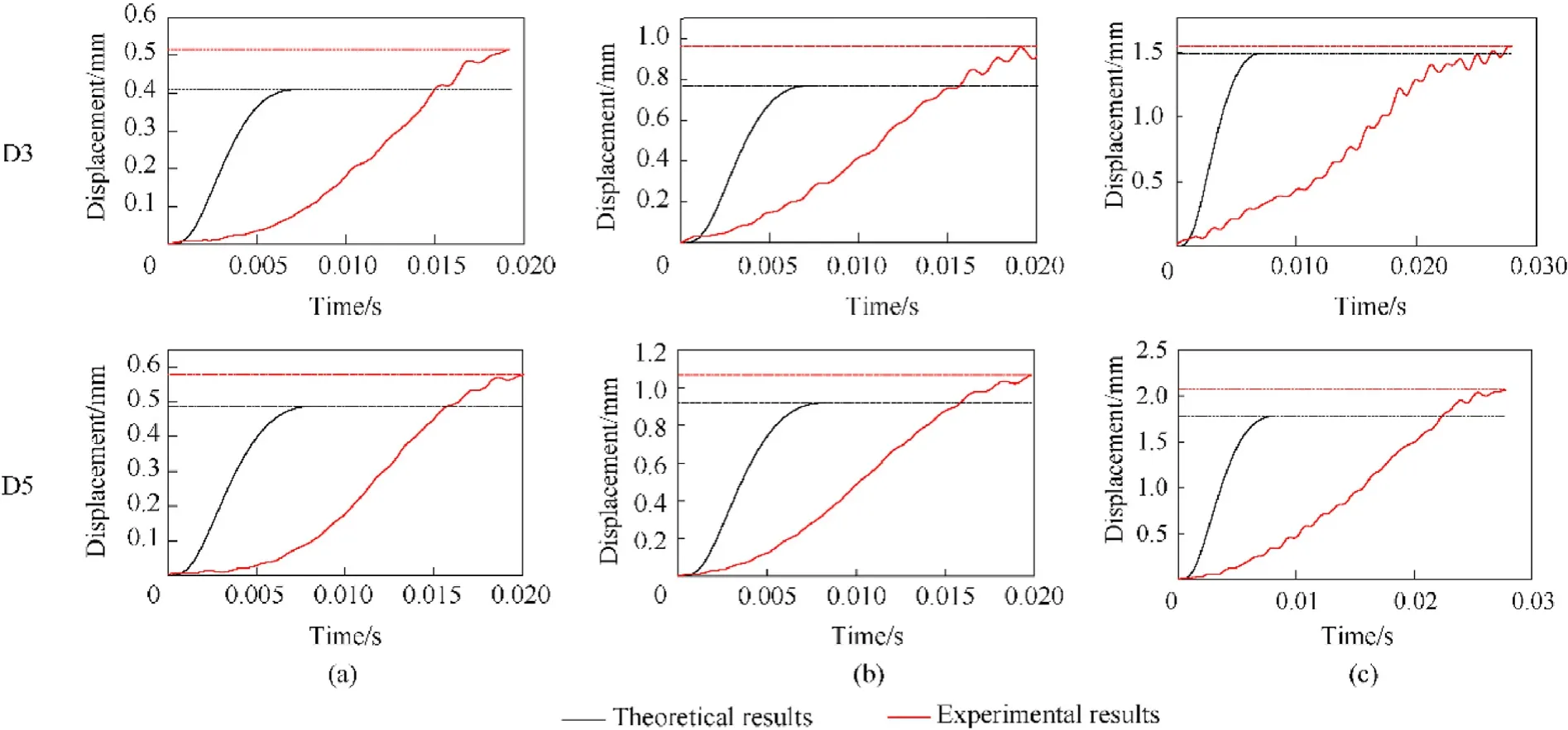
Fig.17.Comparison of displacement time-history curves between experimental data and theoretical results in cases of (a) B1, (b) B2, (c) B3.
The displacements measured in tests at point D3 and D5,which were repaired by CFRP cloth and by Polyurea, respectively, were used to verify this theoretical model.The blast pressure duration time in reducing stage subjected to point D3 and D5,,as well as the distance from measured points to explosion,,are 2.088 m and 0.028 s, respectively.
This theoretical analysis method is based on small deformation hypothesis.The displacement of tunnel roof measured in experiments of cases B1, B2 and B3 are used to verify the theoretical method.The comparison of displacement time-history curves between experimental data and theoretical results at point D3 and D5 in cases B1, B2 and B3 were shown in Fig.17.
The maximum displacements of theory and experiment were listed in Table 8.The maximum displacements of the theory match those of the experiments with acceptable errors in the first three working conditions.

Table 8 Displacements of test and the theory.
6.Strengthening effect of steel bar-reinforced UUT
The experimental tests validated the retrofitting efficiency of the polyurea coating for BBRU.Will this technique still be efficient for steel bar-reinforced UUT (SBRU)? After repetitive explosions, the SBRU showed more severe damage than the BBRU(Fig.18(a)).The roof width was 11.2 mm, and the roof exhibited a large residual deflection[4].The damaged concrete was first removed and re-cast to retrofit the SBRU (Fig.18(b)-(d)).In retrofitting, the soil cover must be removed first, making the retrofitting process more complex and costlier.This procedure was partly reported by Chen et al.[26].
The retrofitting and explosion schemes adopted for SBRU was the same as that of BBRU.The displacement distributions along the SBRU in each case are shown in Fig.19.The regulation was similar to that of BBRU.The polyurea coating was more efficient under intense explosions beyond Case B4.
The retrofitting effect was also validated by comparing the unstrengthened and strengthened SBRUs (Fig.20).Under intense explosion,the retrofitting efficiency of the SBRU was excellent and even better than that of strengthened BBRU, probably induced by the newly cast concrete roof.
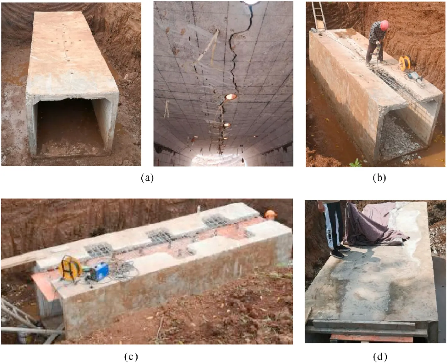
Fig.18.Retrofitting SBRU: (a) Damaged UUT [4], (b) removing damaged concrete, (c) setting up template, and (b) concrete repairing.
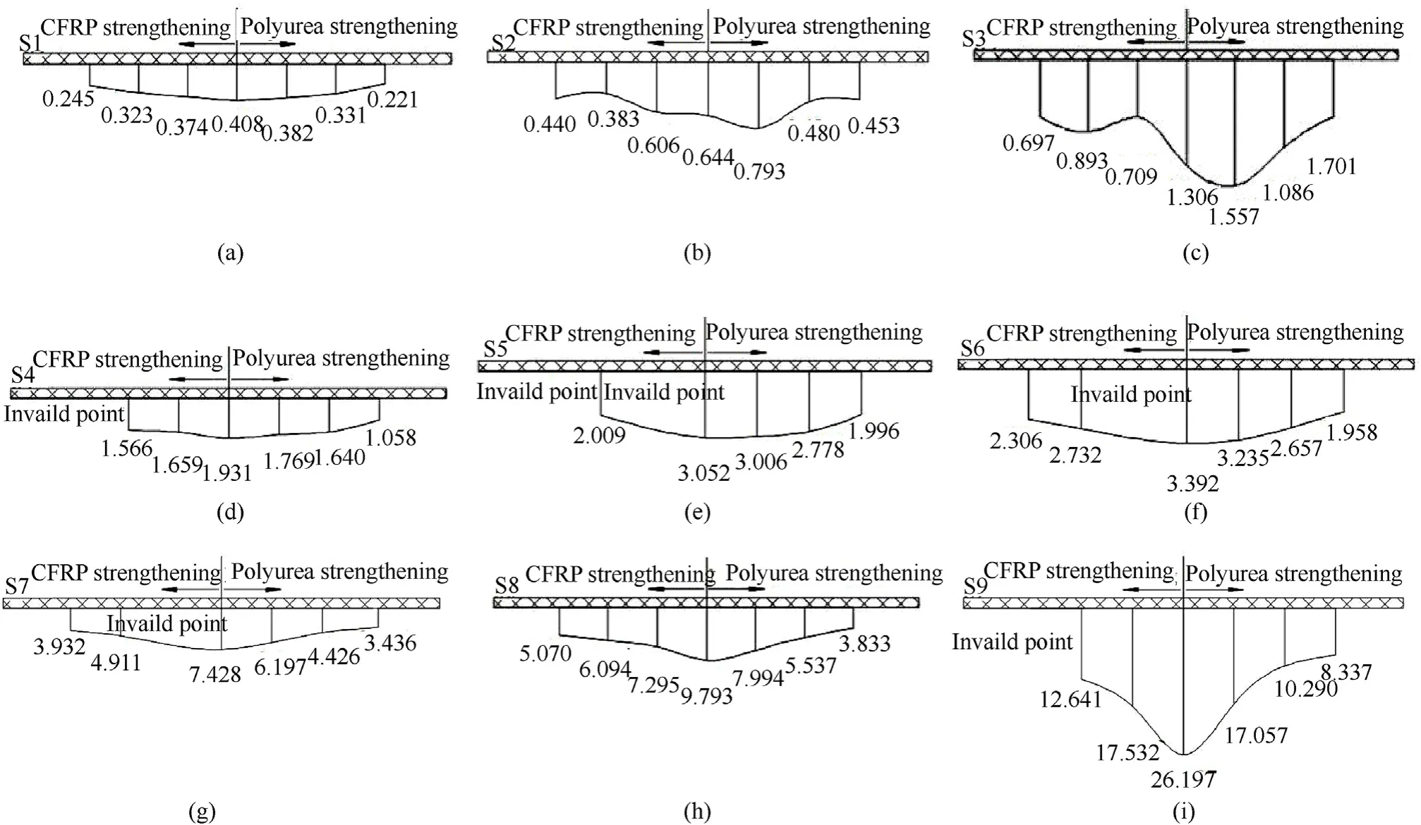
Fig.19.Flexural distribution maps of tunnel roof at (a) B1, (b) B2, (c) B3, (d) B4, (e) B5, (f) B6, (g) B7, (h) B8, and (i) B9.
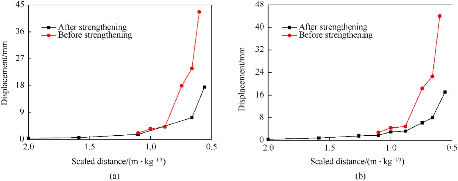
Fig.20.Displacement comparisons: (a) D3 retrofitted using CFRP cloth and (b) D5 retrofitted using polyurea coating.
7.Conclusions
Through in-field explosion experimental tests, the retrofitting effects of two strengthening techniques were investigated and evaluated.The following conclusions can be drawn:
1) Both polyurea coating and CFRP strengthening techniques are efficient for retrofitting blast-damaged UUTs using steel or BFRP bars as reinforcement.This viewpoint was verified based on the smaller deformation and weaker damage of the retrofitted UUTs after repetitive explosions.
2) The CFRP-strengthened UUT exhibited better performance under weak explosions, attributed to the smaller displacement.However, polyurea-coated UUT exhibited better performance under intense explosions, as confirmed through the smaller displacement.The critical scaled distance in this study was 0.881 m/kg.
3) Why did the CFRP-strengthened UUT not perform satisfactorily?The delamination of the CFRP from the concrete surface was the critical factor,which was validated by the abrupt decrease in the strain of the CFRP cloth when the scaled distance was 0.881 m/kg.The tight adhesive strength of the interface between the polyurea coating and the concrete guaranteed excellent retrofitting performance.
4) The advantage of BFRP bar-reinforced UUT was also attributed to retrofitting.More severe damage to the steel bar-reinforced UUT significantly increased the complexity and costs of retrofitting with additional removal and re-casting of the concrete roof.
5) Elastic deformation of the UUT under explosion can be effectively predicted by elastically simply supported beam theory considering the interaction between soil and structure.But the theory can hardly predict the plastic deformation.
The authors declare that they have no known competing financial interests or personal relationships that could have appeared to influence the work reported in this paper.
This work was supported by National Natural Science Foundation of China [51778622]; Social Development Project of Science and Technology Department of Jiangsu Province [BE2017780];Jiangsu Natural Science Foundation Youth Project [BK20190573].
- Defence Technology的其它文章
- Defence Technology
- Roll angular rate extraction based on modified spline-kernelled chirplet transform
- Buckling of composite cylindrical shells with ovality and thickness variation subjected to hydrostatic pressure
- Preparation of the core-shell HMX@CS microparticles by biological excitation:Excellent hydrophobic-oleophilic properties and decreased impact sensitivity effectively
- Quantitative prediction and ranking of the shock sensitivity of explosives via reactive molecular dynamics simulations
- An efficient light-to-heat conversion coupling photothermal effect and exothermic chemical reaction in Au NRs/V2C MXene membranes for high-performance laser ignition

