Dynamics of luffing motion of a hydraulically driven shell manipulator with revolute clearance joints
Chen Zhi-qun , Qin Lin-fng ,b, Chen Gung-song , Nie Shou-heng , Yin Qing ,*,Yue Ci-heng
a School of Mechanical Engineering, Nanjing University of Science and Technology, Nanjing, 210094, China
b Northwest Institute of Mechanical and Electrical Engineering, Xianyang, 712099, Shaanxi, China
c China North Industry Corporation, Beijing,100053, China
Keywords:Parameter identification Shell manipulator Hydraulic cylinder Revolute clearance joint
ABSTRACT In this study, a modeling method for investigating the dynamic characteristics of a hydraulically driven shell manipulator with revolute clearance joints is presented. This model accounts for the effect of the clearance, the flexibility of the rotating beam, and the coupled dynamic characteristics of the hydraulic cylinder. A modified contact force model was developed to simulate the physical properties of realistic revolute joints with small clearances, heavy loads, and variable contact stiffnesses and damping coefficients with variations of the indentations. Considering the strong coupling relationship between the hydraulic cylinder and the flexible beam, a system equation of motion combining the state variables of the hydraulic cylinder and mechanical system was established. The complex nonlinear friction force of the hydraulic cylinder motion was constructed using a modified LuGre model,and the parameters of the friction model were identified using intelligent identification algorithms.Moreover,a test system for the shell manipulator was established to achieve experimental validation.Finally,the effects of the clearance size and the stiffness of the cylinder support on the dynamic response were investigated.
1. Introduction
The shell manipulator is an essential part of the automatic loading system of large-caliber artillery.It is mainly used to receive the shell from the magazine and then transfer the shell to the ammunition ramming position. After the shell is rammed into the barrel by the ammunition rammer,the shell manipulator returns to the original position to wait for the next shell [1]. The shell manipulator has the characteristics of a large load, large mass moment of inertia, high flexibility, and high rotational speed.Therefore, a hydraulically driven device is usually used as an actuator to provide a high transmission power and enhance the system support stiffness. The task of the shell manipulator is to transport the shell quickly and accurately to the required angles of fire. However, in actual service, the complex and harsh working environments may lead to positioning errors and chattering of the shell manipulator,which significantly reduces the reliability of the whole ammunition automatic loading system. Therefore, it is urgent to develop a dynamic model that can accurately describe the actual physical state of the shell manipulator to clarify the motion characteristics of a shell manipulator.
The configuration of the shell manipulator is similar to that of industrial robots,construction cranes,large solar panels,and other high-speed rotating and lifting mechanisms. The interaction between the large overall motion and the elastic deformation of the flexible component significantly affects the stability and precision of the mechanism [2]. Meanwhile, various factors can give rise to the existence of clearance in the mechanism, such as the design requirements, manufacturing and assembling errors, material deformation, and wear. The impact force and friction force generated at the clearance joint lead to vibration noise and wear and further affect the operation accuracy,stability of the response state,and service life of the mechanical system[3].
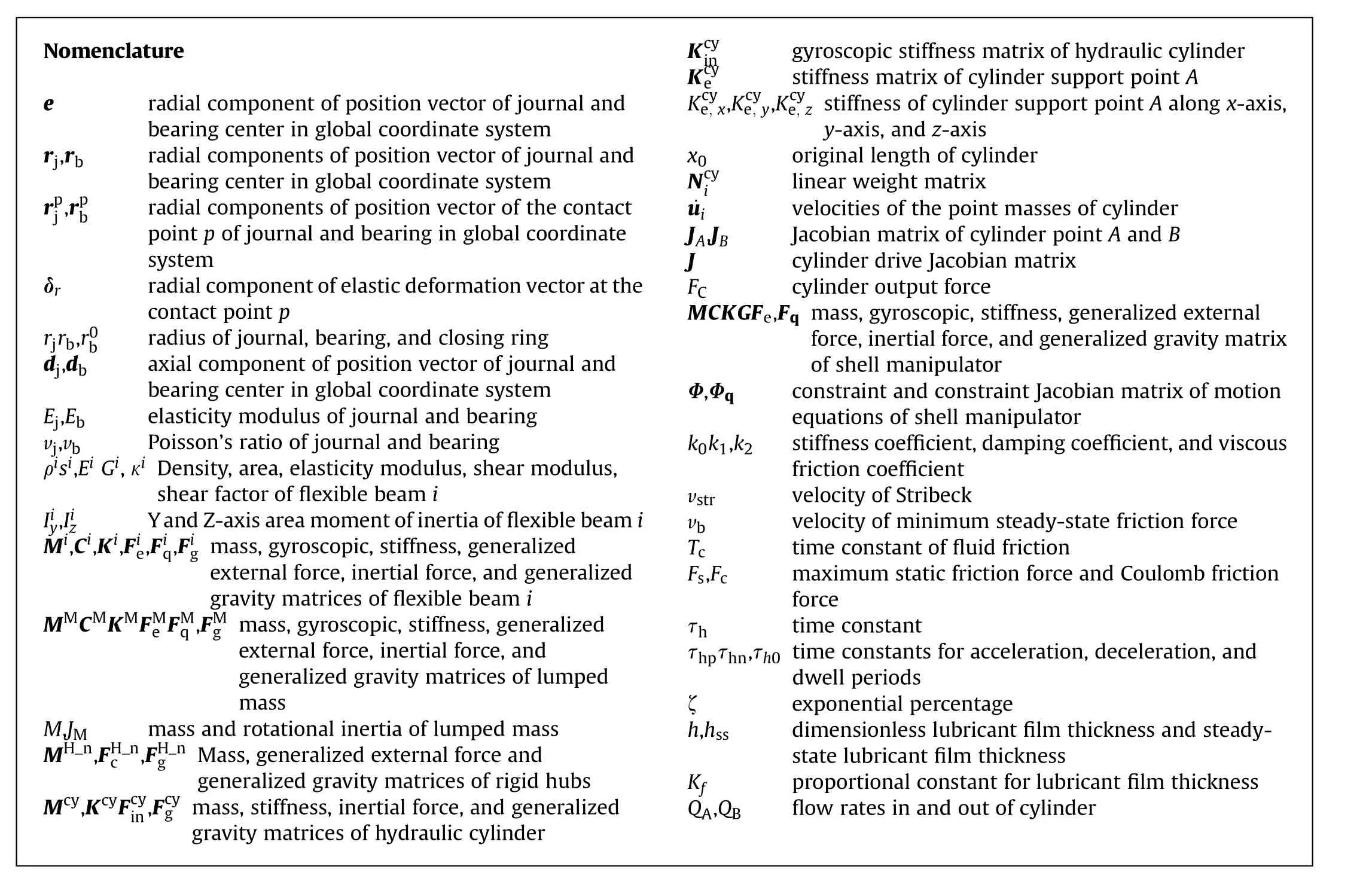
Nomenclature e Kcy ingyroscopic stiffness matrix of hydraulic cylinder radial component of position vector of journal and bearing center in global coordinate system rj,rbradial components of position vector of journal and bearing center in global coordinate system rpj,rp b radial components of position vector of the contact point p of journal and bearing in global coordinate system δrradial component of elastic deformation vector at the contact point p rjrb,r0bradius of journal, bearing, and closing ring dj,dbaxial component of position vector of journal and bearing center in global coordinate system Ej,Ebelasticity modulus of journal and bearing vj,vbPoisson’s ratio of journal and bearing ρisi,Ei Gi,κi Density, area, elasticity modulus, shear modulus,shear factor of flexible beam i Iiy,IizY and Z-axis area moment of inertia of flexible beam i Mi,Ci,Ki,Fie,Fiq,Fig mass, gyroscopic, stiffness, generalized external force,inertial force,and generalized gravity matrices of flexible beam i MMCMKMFMe FMq ,FMg mass, gyroscopic, stiffness, generalized external force, inertial force, and generalized gravity matrices of lumped mass M,JMmass and rotational inertia of lumped mass MH_n,FH_n c ,FH_ngMass, generalized external force and generalized gravity matrices of rigid hubs Mcy,KcyFcy in,Fcyg mass, stiffness, inertial force,and generalized gravity matrices of hydraulic cylinder Kcyestiffness matrix of cylinder support point A Kcye, x,Kcye, y,Kcye, z stiffness of cylinder support point A along x-axis,y-axis, and z-axis x0original length of cylinder Ncy ilinear weight matrix ˙uivelocities of the point masses of cylinder JA,JBJacobian matrix of cylinder point A and B J cylinder drive Jacobian matrix FCcylinder output force MCKGFe,Fq mass, gyroscopic, stiffness, generalized external force,inertial force,and generalized gravity matrix of shell manipulator Φ,Φqconstraint and constraint Jacobian matrix of motion equations of shell manipulator k0k1,k2stiffness coefficient,damping coefficient,and viscous friction coefficient vstrvelocity of Stribeck vbvelocity of minimum steady-state friction force Tctime constant of fluid friction Fs,Fcmaximum static friction force and Coulomb friction force τhtime constant τhpτhn,τh0 time constants for acceleration, deceleration, and dwell periods ζexponential percentage h,hssdimensionless lubricant film thickness and steadystate lubricant film thickness Kfproportional constant for lubricant film thickness QA,QBflow rates in and out of cylinder
With the development of equipment quality and technology,flexibility and low weights have become a trend of equipment upgrading and transformation. The theoretical and practical research on flexible rotating beam structures, which are widely used in engineering, has attracted numerous scholars in recent decades. Bauer [4,5] established a flexible multi-body system dynamics model utilizing the combination of the zero approximation method and the floating coordinate method to depict the dynamic behaviors of vertical and horizontal rotary beams under different boundary conditions.Kane[6]and Yoo[7]investigated the effect of the coupling between the stretching and bending motion on the modal features of the flexible beam undergoing overall movement and then introduced the phenomenon of dynamic stiffening. Lee[8] built a bending motion model of a rotating beam considering the effect of the tip mass; meanwhile, the effects of the rotational inertia, rotational velocity, and cross-sectional parameters of the beam on the natural frequency of the beam were discussed.Hua[9]established an eccentric rotating beam dynamic model and researched its periodic motion characteristics under a continuous impact load.The analysis of the Bernoulli-Euler beam model,shear beam model, and Timoshenko beam model for rotating composite beams was presented by Aksencer[10].Bahaadin[11]used rotating beam theory to analyze the dynamic behaviors of functionally graded polymer composite thin-walled rotating blades reinforced with multilayer graphene nanoplatelets in supersonic flow. Similarly, the dynamics of flexible rotating mechanisms/lifting mechanisms actuated by hydraulic cylinders have been studied extensively. The dyfignamic response of a hydraulically driven single-arm flexible crane was researched by Sun [12]. Cibici [13]developed a dynamics model of a flexible knuckle boom crane using screw theory. Meanwhile, the bond graph method was adopted to couple the dynamics model and mass balance of the hydraulic cylinder. Henikl [14] presented a method for the mathematical modeling of a hydraulic manipulator considering both the static friction force and elastic deformation,and the validity of the modeling method was verified through the experiments. Tra˛bka[15]utilized the finite element method to analyze the influences of the number of elastic components on the dynamic characteristics of the crane.
The aforementioned studies focused on the effect of flexibility on the dynamic response and neglected the clearance. It is remarkable that the existence of clearance will lead to strongly nonlinear dynamics. Numerous scholars have proposed several approaches to establish contact force and impact dynamics models for hinge mechanisms with clearance over the past decade.
Flores et al. investigated the effects of clearance joints [16,17],wearing clearance [18], number of clearance joints [19], contact force model[20],and lubricated revolute joints[21]on the dynamic characteristics of the planar rigid multibody system. They also proposed a simple and efficient computational method for contact detection [22] and analyzed the effect of Baumgarte stability parameters on the forward dynamics numerical integration errors of constrained multibody systems with clearance [23]. Bai et al. [24]researched the dynamic behaviors of a 4-bar mechanism with regular and irregular clearance formed by wear,and the simulation results showed that the wear of the clearance joint would distinctly change the response characteristics of multibody mechanical systems. Virlez et al. [25] proposed a new three-dimensional cylindrical joint model considering clearance, eccentricity, and friction;it was utilized to analyze the dynamic characteristics of automobile transmissions. Ma et al. presented a new hybrid model [26] and used it to analyze the influence of dynamic interactions of three revolute clearance joints on the planar 4-bar mechanism[27].They studied a parameter identification method of contact collision to obtain the dynamic parameters of the contact force model[28-30].Yan [31] presented a three-dimensional revolute joint model with axial and radial clearances considering the effect of eccentricity between the shaft and the bearing. The effectiveness of the threedimensional revolute joint model was proven by comparing simulation and experimental results. Based on the studies of clearance joint lubrication force models for a multi-body system conducted by Flores and Lankarani [32], Tian et al. introduced a lubricating film force into the clearance joint to establish a dynamics model of the flexible multibody system with lubrication and analyzed the dynamic characteristics of the system under different lubrication force models[33-35].Subsequently,they methodically summarized previous relevant studies involving kinematic and dynamic analyses of multibody systems with the translational,planar, spherical, and spatial clearance joint [36]. Erkaya et al.[37-39] analyzed the effects of joint clearance and flexible connections on mechanical vibrations through numerical and experimental research. Based on the fast Fourier transform algorithm,Salahshoor et al.[40]investigated the vibration characteristics of a typical flexible crank slider mechanism with flexible components and joint clearances and compared the influence of the joint stiffness, clearance size, and coupler axial deformation on its dynamic responses. Zheng et al. [41] proposed a modified computational method for the modeling and simulation of multilink high-speed precision presses considering the effects of the flexibility of the linkage and crankshaft,supporting bearing stiffness,and clearance.
Due to the strong universality of commercial software,they are widely used in the research of the dynamic behaviors of flexible rotating beams and mechanisms with joint clearances [42]. However, the parameters default setting of the contact and friction models used in commercial software are lack of flexibility.They are set depending on the experience of operators and do not change over time in calculating process. All these shortcomings limit the accuracy of the calculation results when the clearances are considered.
Although, recent years, a flood of researches have been investigated on the dynamic characteristics of rigid-flexible mechanism with clearance joint[59],these studies generally have the following defects. (a)The dynamic stiffening phenomenon is ignored,which will lead to the deformation error under the high-speed rotation.(b) The influence of the complicated dynamic behavior of driving system is neglected,which will lead to the decrease of the analysis precision. (c) The Hertz distribution assumption is adopted to construct the contact force model,which only estimate the contact force roughly with conformal contact conditions often observed for low clearances.
In order to analyze the dynamic characteristics of the shell manipulator more reasonably and accurately, this paper presents an improved computational model of a hydraulically driven shell manipulator with revolute clearance joints.This methodology fully accounts for the effects of revolute clearance, the flexibility of the rotating arm, and the dynamic characteristic of the hydraulic cylinder.The modified contact force model was developed to simulate the physical properties of realistic revolute joints with small clearances,heavy loads.A quadratic coupling term of the arc length stretch caused by the transverse bending deformation is introduced in the beam deformation description.It effectively characterizes the effect of dynamic stiffening under the high-speed rotation and avoids numerical divergence in calculation.To construct the driving characteristics, the strong coupling relationship between the hydraulic cylinder and the flexible beam is built. Meanwhile, the complex nonlinear friction behavior of the hydraulic cylinder motion was included. Moreover, the improved model was verified by experiments. Finally, the dynamic responses of the shell manipulator under different clearance sizes and stiffnesses of the cylinder support were investigated.
2. Physical description
Simplified diagrams of the specific structure and X-Y plane of the shell manipulator are shown in Fig.1.The shell manipulator can be divided into three parts in terms of different functions:the main frame, hydraulic actuator, and ramming mechanism. The main frame is the main load-bearing assembly,which is made of several rectangular tubular trusses welded at the joints. The hydraulic actuator is an actuating component that drives the manipulator to rotate around the Z-axis. The ramming mechanism is used to grab and convey the shell. To facilitate this study, we made some reasonable simplifications and assumptions.
Hubs (1) and (2) are rotating hubs on both sides of the shell manipulator. The hubs are not the major components bearing the bending moment,and their area moments of inertia are larger than those of the other components. Thus, they are considered to be rigid bodies,ignoring their flexible deformation.Flexible beams(1),(2), (3), and (4) are the major components bearing the bending moment in the shell manipulators. The flexible deformations of these components have a tremendous impact on the motion characteristics for the shell manipulator. The front end of flexible beams (1) and (2) are welded with rigid center hubs (1) and (2),respectively. Flexible beam (3) is the middle connecting component,which is welded to the rear sides of the flexible beams(1)and(2).
The front end of flexible beam (4) is bolted to middle flexible beam(3);its longitudinal symmetry plane coincides with the midpoint plane of the middle flexible beam (3). Ramming mechanism(7) fixed on flexible beam (4) by bolts. In the process of the manipulator’s rotation, there is no operation on the ramming mechanism. Therefore, it can be considered to be a lumped mass attached to flexible beam (4) in this study. Rear support (9) is welded on a cantilever truss in the actual physical prototype.Therefore, the effect of its stiffness on the rear support of the hydraulic cylinder is considered.
Due to the small slenderness ratio of these flexible beams,Timoshenko theory is chosen to construct the flexible beam model.Based on the physical structure of the beams,flexible beams(1),(2),and(4)are considered to be cantilever beams,and flexible beam(3)is considered to be a clamped beam.A combined bearing is adopted in the two revolute joints of the hydraulic cylinder, and the assembly between the pin and inner ring of the combined bearing is interference fit. Thus, the revolute joints of the hydraulic cylinder can be regarded as ideal joints. Due to the complexity of the assembly process, it is difficult to eliminate the clearances at the Hand Hjoints. To analyze the dynamic characteristics of the shell manipulator accurately, the effect of the clearances at Hand Hshould be considered.
3. Model of hydraulically driven shell manipulator with revolute clearance joints
3.1. Model of revolute clearance joint
3.1.1. Mathematical model of joint with clearance
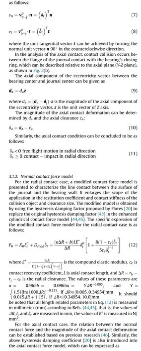
The revolute clearance joint of the shell manipulator consists of the hubs’bearing and journal,as shown in Fig.2.Because the radial clearance is much smaller than the length of the shaft and the manipulator is subjected to a heavy load, this negligible misalignment effect on the clearance joint is ignored. There are four scenarios for the motion relations between the bearing and journal,namely: (i) free flight motion where there is no contact between journal and bearing; (ii) the surface of the journal contacts the bearing wall at a line; (iii) the flange of the journal contacts the bearing’s closing ring at an annular plane; (iv) contact on an annular plane coexists with contact at a line.
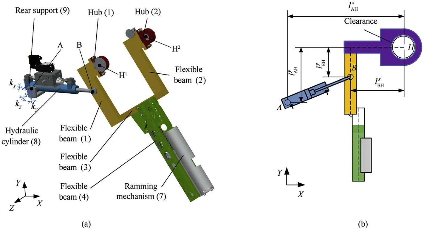
Fig.1. Configuration of shell manipulator: (a) 3D structure; (b) Simplified diagram of the X-Y plane.
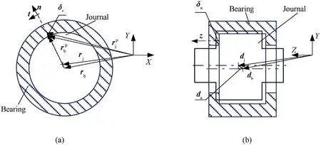
Fig. 2. Revolute joint clearance with contact: (a) radial contact (X-Y plane) and (b) axial contact (Y-Z plane).
In the analysis of the radial contact, contact collision occurs between the surface of the journal contact with the bearing wall,which can be described in accordance with the radial plane (X-Y plane), as illustrated in Fig. 2(a).
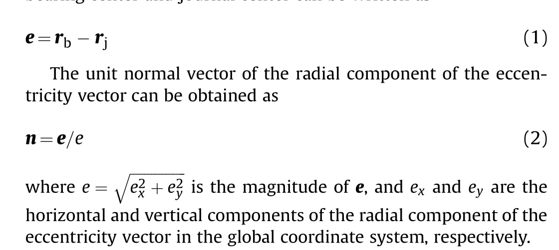
The radial component of the eccentricity vector between the bearing center and journal center can be written as
When the bearing comes into contact with the journal, the radial component of the contact deformation vector at the contact point p is
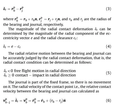
The relative normal velocity vand the relative tangential velocity vof the contact points in the radial direction can be obtained
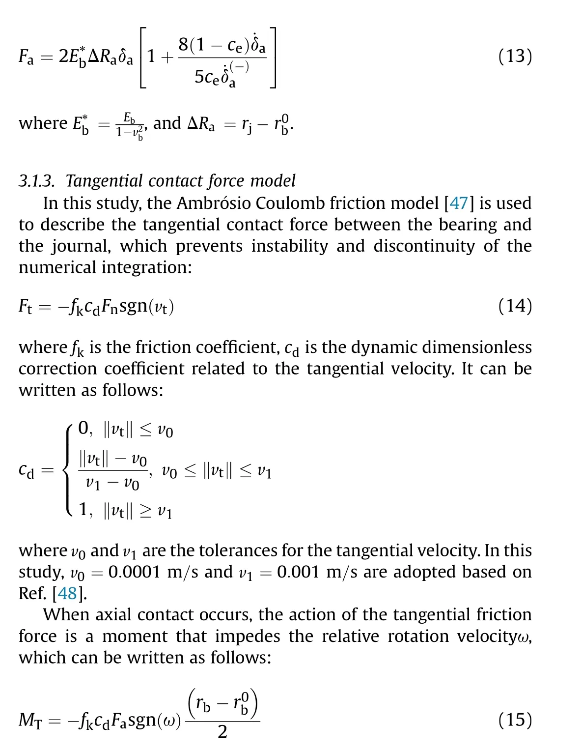
3.2. Model of flexible beam
A floating frame of reference approach is used to model the motion of the flexible beam of the shell manipulator,as illustrated in Fig. 3. The position vector of point pon the deformed flexible beam i in the global coordinate system can be written as
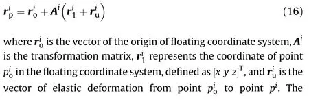
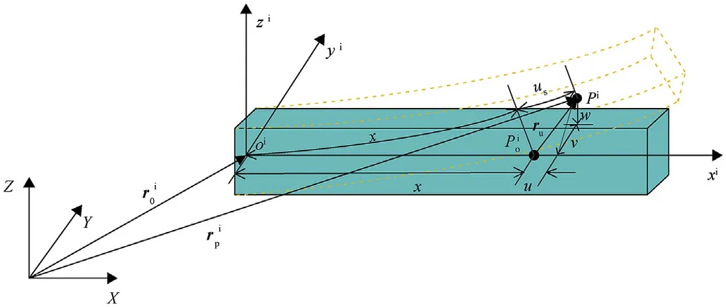
Fig. 3. Description of deformation of flexible beam.
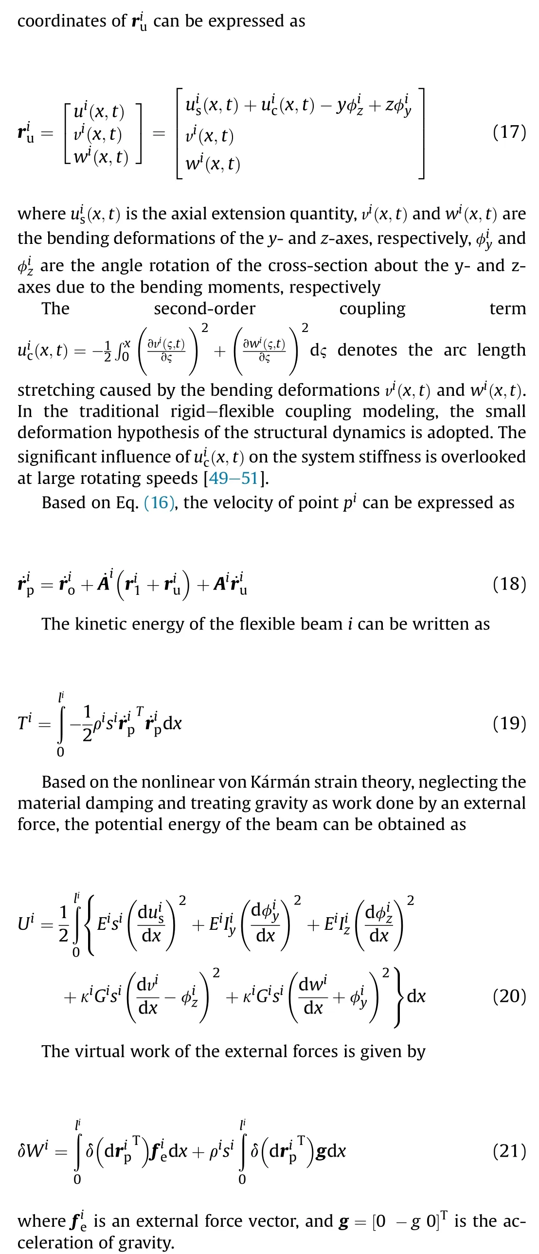
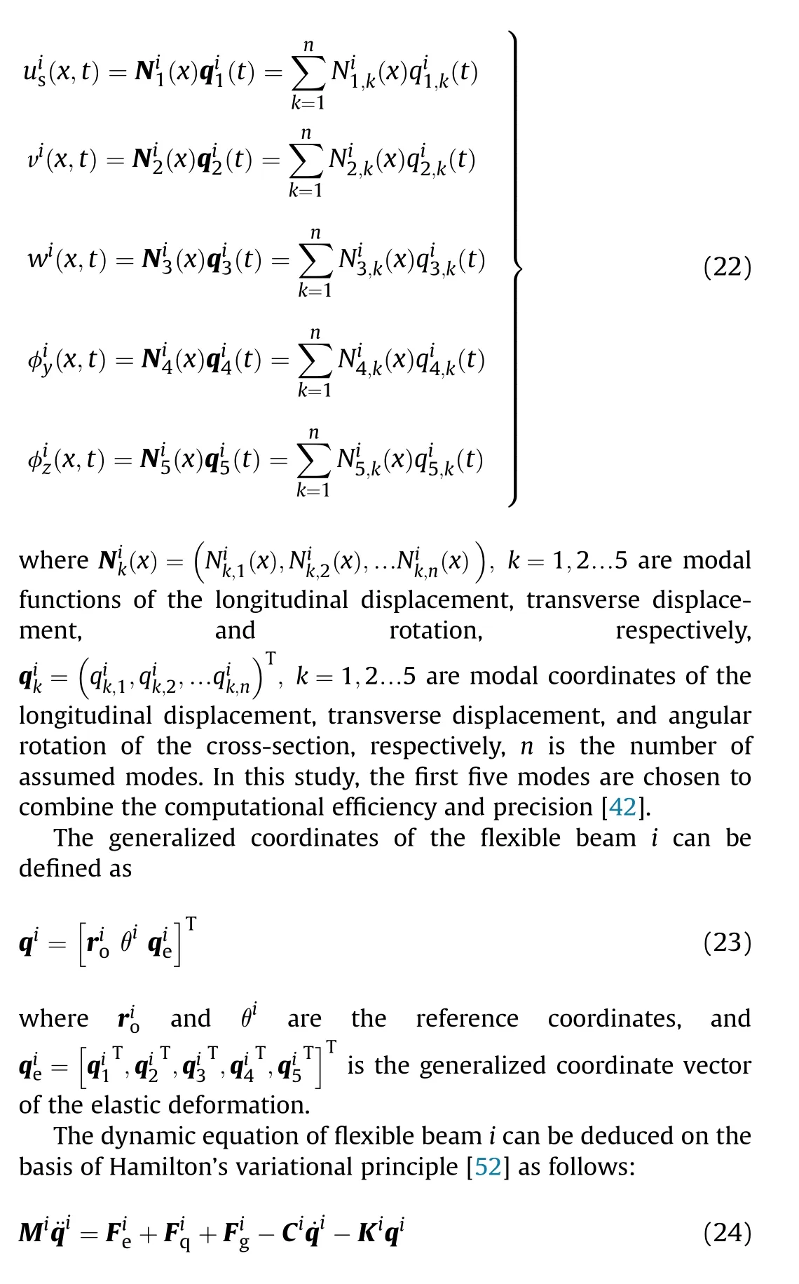
To reduce the high-frequency oscillation excitations arising from high-order modes and the number of elastic coordinates,the method of modal superposition is used to represent the elastic vibrations on the flexible beam,and the specific form is as follows:
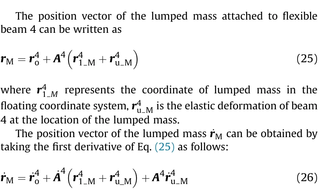
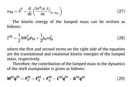
3.3. Model of lumped mass
Neglecting the insignificant angular velocity around the x and y axes, the angular velocity of the lumped mass is obtained as follows:
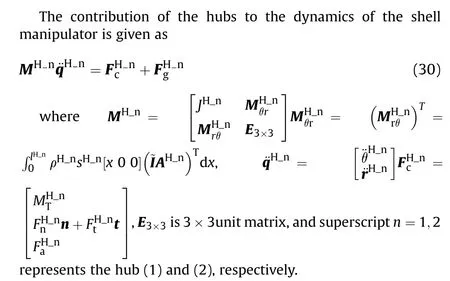
3.4. Model of rigid hubs
3.5. Coupling of manipulator and cylinder modelsown
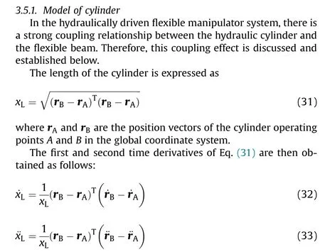

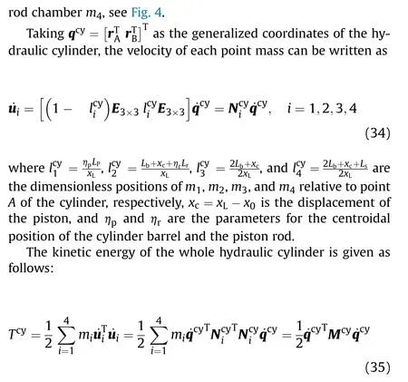
where the masses of the cylinder barrel and the piston rod are constant.However,the masses of the hydraulic fluid vary,and they can be expressed as follows:

where ρis density of hydraulic oil, Vand Vare the initial fluid volumes in rodless chambers and rod chambers, respectively, sand sis the area of rodless chambers and rod chambers,respectively.
Since the mass matrix of the cylinder is a function of the displacement of the piston, the gyroscopic stiffness is introduced into the equation of motion.The gyroscopic stiffness matrix shown in Eq. (38) is obtained by taking the first variation of the inertial force
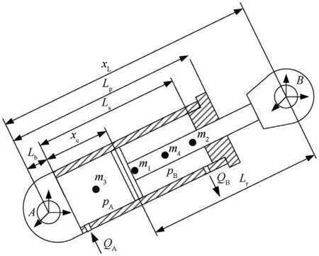
Fig. 4. Main dimensions and variables of hydraulic cylinder element.
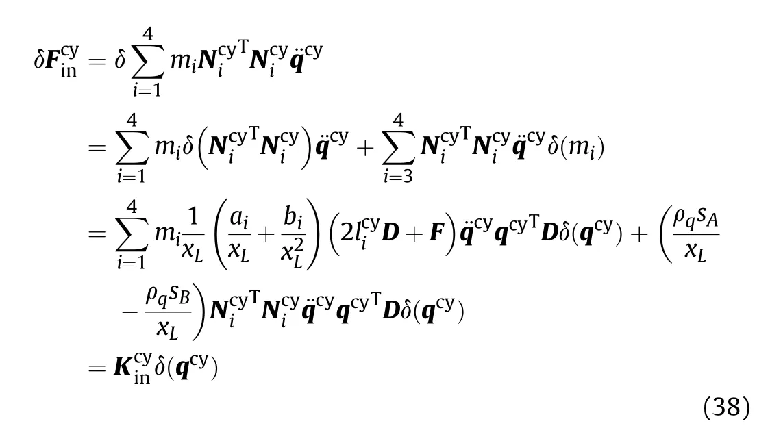
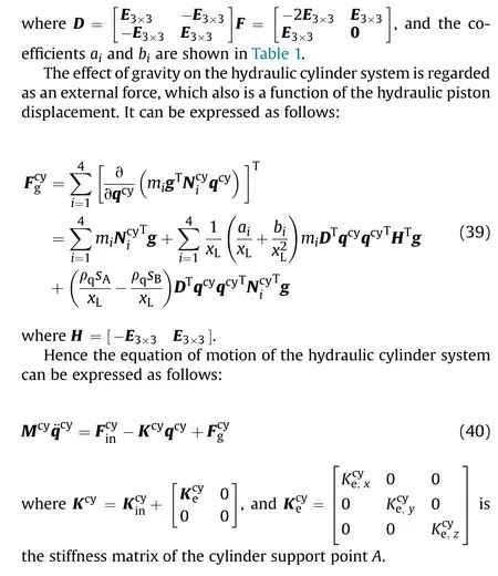
3.5.2. Generalized force of hydraulic cylinder
The point B is the coupling point between the hydraulic system and the mechanical system. Hence, its position vector can also be expressed using the generalized coordinates of flexible beam 1,and the generalized coordinates of the shell manipulator system can be defined as follows:

The coordinate of B is defined as [x0 z]in the floating coordinate system of flexible beam (1), and the expression form of rcan be obtained as follows:


Table 1 Derivative coefficients o
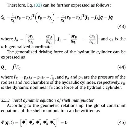
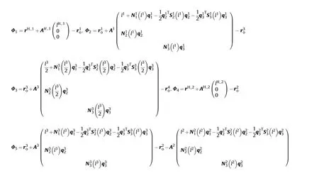
where Φis the position constraint between the rear end of hub(1)and the front end of flexible beam(1),Φis the position constraint between the rear end of flexible beam (1) and the front end of flexible beam (3), Φis the position constraint between the midpoint of flexible beam (3) and the front end of flexible beam (4),Φis the position constraint between the rear end of hub (2) and the front end of flexible beam (2), Φis the position constraint between the rear end of flexible beam (3) and the front end of flexible beam (2), the specific expression forms of Φ-Φare as follows:
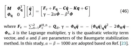
Combining the equations of motion of the revolute clearances,flexible beam,lumped mass,rigid hubs,and hydraulic cylinder,the nonlinear dynamics equation of the shell manipulator can be expressed as follows:
The variable step-size Runge-Kutta-Fehlberg method(RKF45)is used to solve the dynamics equation of the shell manipulator.Fig.6 shows the computational procedure of hydraulically driven shell manipulator with revolute clearance joints, and the parameters of the shell manipulator for the simulation are listed in Table 2).
4. Friction model and parameter identification
4.1. Nonlinear friction model of cylinder friction
The dynamic friction force is presented as a product of two functions,where one depends on the pressure of the two chambers and the other depends on the velocity of the piston ˙x,and z is the bristle deformation[53],as shown in Fig.5.The specific expression of the nonlinear friction force is as follows:
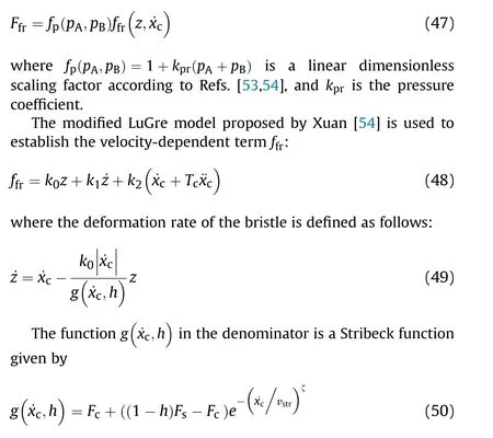
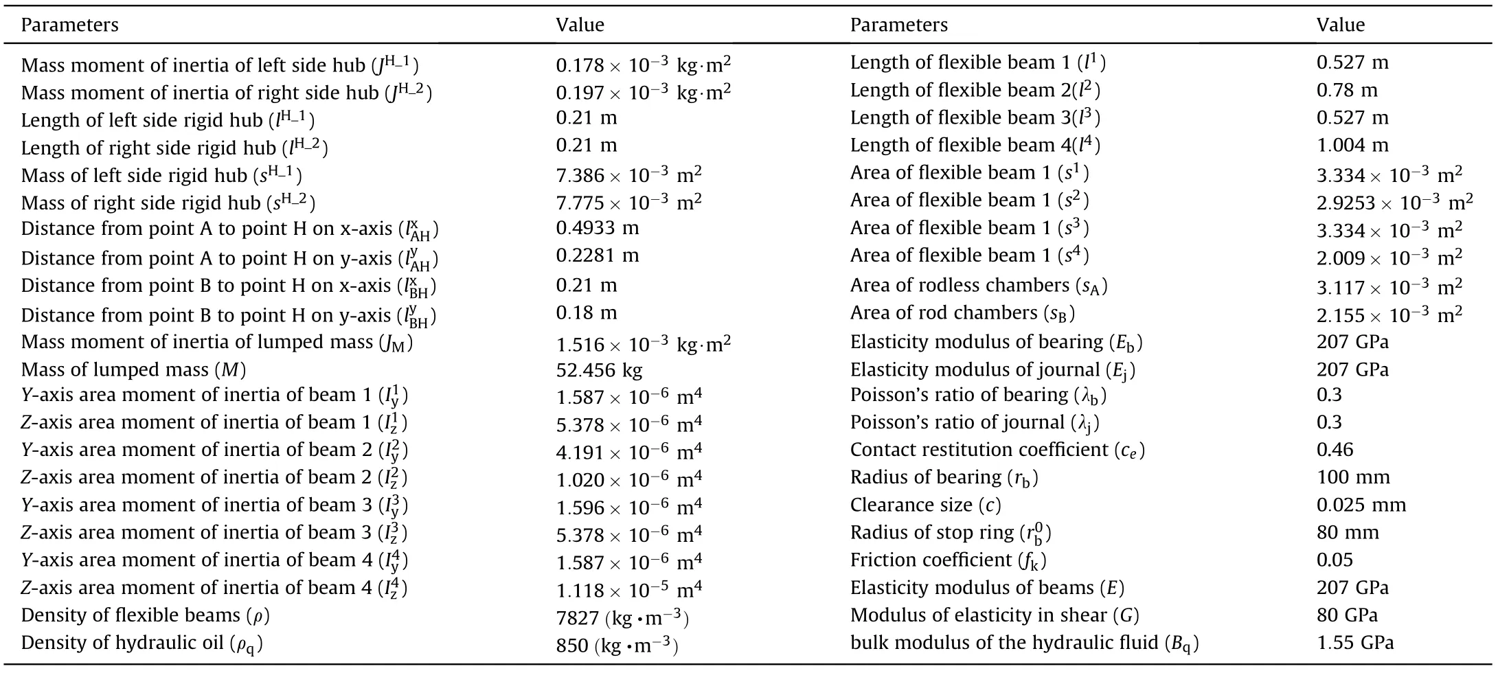
Table 2 Simulation parameters of the shell manipulator.
The lubricant film dynamics model with a varying time constant is expressed as follows [55]:
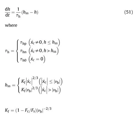
The state equation for the variables of the friction model can be written as follows:
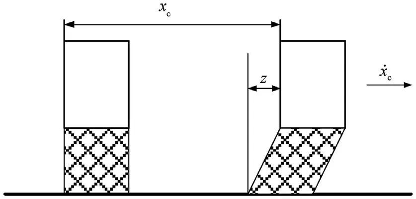
Fig. 5. Piston sealing ring deformation z.
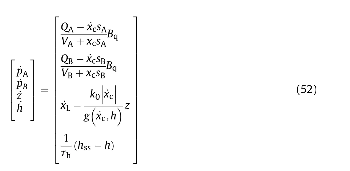
where Bis the bulk modulus of the hydraulic fluid, which is a function of the fluid pressure.However,it can be assumed that the volume modulus is constant in practical engineering applications[56].
4.2. Friction parameter identification
To determine the friction force of the cylinder in the shell manipulator, it is necessary to accurately identify the relevant parameters in the nonlinear friction model.Referring to the research in Refs. [54,55], the test scheme is designed and implemented on the shell manipulator prototype. The test procedure is to measure the relative physical parameters under a varying piston velocity and then determine the dynamic friction characteristics. Based on the possible speeds of the actual working conditions of the cylinder,the piston speed of the cylinder is designed as follows:

where m is the load mass, and a is the acceleration of the piston.
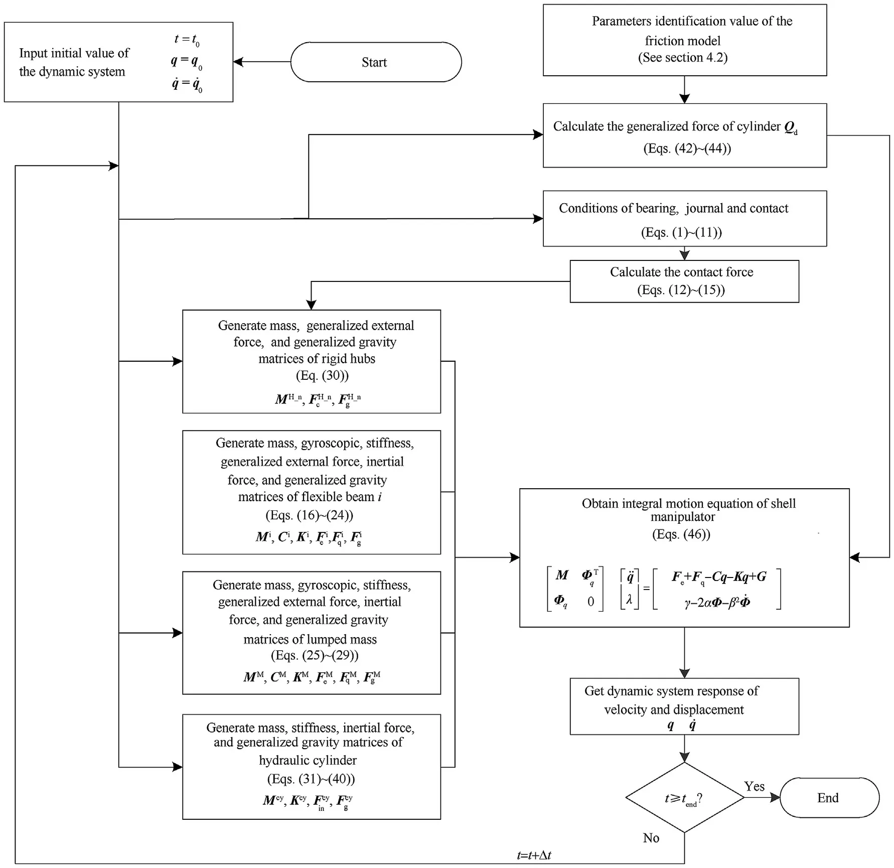
Fig. 6. Flowchart of algorithm used for dynamic analysis of hydraulically driven shell manipulator with revolute clearance joints.

Table 3 Parameters of the algorithm for friction parameter identification.
Although the uncertain parameters(k,k,k,k,T,F,F,v,v,ζ,τ,τ,τ) of the cylinder friction model in Eq. (48) can be identified by the method in Ref.[55],it will introduce a large error due to lack of engineering experience and unreasonable assumptions. To avoid the calculation errors caused by insufficient cognition, an improved multi-extremum-learning particle swarm optimization algorithm (MELPSO) [57] is used to search for the optimal values in the solution space to identify these parameters.MELPSO prevent premature convergence and stagnation that appear on traditional PSO frequently especially in non-linear parameters identification problems.
The error of the parameter identification can be calculated asfollows:
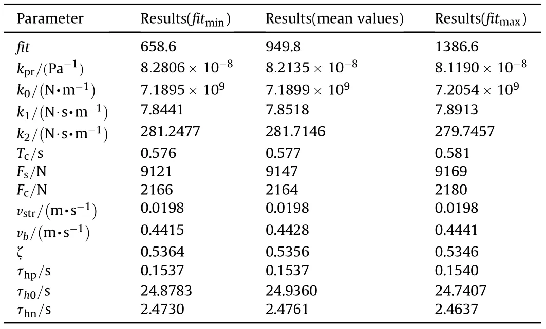
Table 4 Friction parameter identification results.
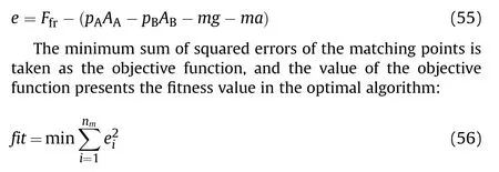
The related parameters of the algorithm for friction parameter identification are shown in Table 3. Meanwhile, the identification algorithm was performed 10 times to obtain the identification values and verify the consistency of the identification results. The parameter identification results obtained by multiple computations are very close, as seen in Table 4. Although the fitness value has a large deviation,the average force error allocated to each matching point is less than 5 N,so the consistency of identification results is verified.The measured velocity variations of the cylinder are shown in Fig.7(a),the convergence curve is shown in Fig.7(b),the friction force-time curve is shown in Fig. 7(c), and the friction force-velocity curve is shown in Fig. 7(d). After nearly 230 iterations,the MELPSO achieved convergence.Based on Fig.7(d),it can be concluded that the theoretical nonlinear friction model could simulate the dynamic behaviors of friction accurately under variable-velocity circumstances. The results indicate that the MELPSO was an effective method to achieve the ideal identification effect.
5. Model verification
5.1. Validation of the planar problem solver
In order to verify the effectiveness of the proposed method,we carried out a comparison case referring to section model verification in Ref.[2].It is should be noted that the axial contact length L was not defined in Ref.[2].Here,it is chosen as 10 mm so that the contact stiffness values are basically the same in different model.
The comparison results of the main motion characteristics are presented in Figs. 8-11. It can be seen from Figs. 8 and 9 that the calculation results of the contact force used the method proposed in this paper are very close to those obtained by the other two methods. It proves that the improved contact model proposed in this paper can accurately describe the contact-collision motion at the clearance joint. Due to the different setting of damping parameters, the contact force calculated by different method exist phase differences. The angle and angular velocity curves of the planar flexible beam under different dynamic model are displayed in Figs.10 and 11.Obviously,the numerical solution of the proposed model shows well agreement with the results obtained by Ref. [2]and the commercial soft.In addition,from partial enlarged detail in Fig. 11, the fluctuations in angular velocity are presented in the models proposed in this paper and Ref. [2] after 4 s. However, the result of commercial software was lost vibration information. This indicates that the coupling characteristics between flexible and rigid body motion have been considered based on the model presented in this paper and Ref.[2]which would obtain more accurate dynamic response.
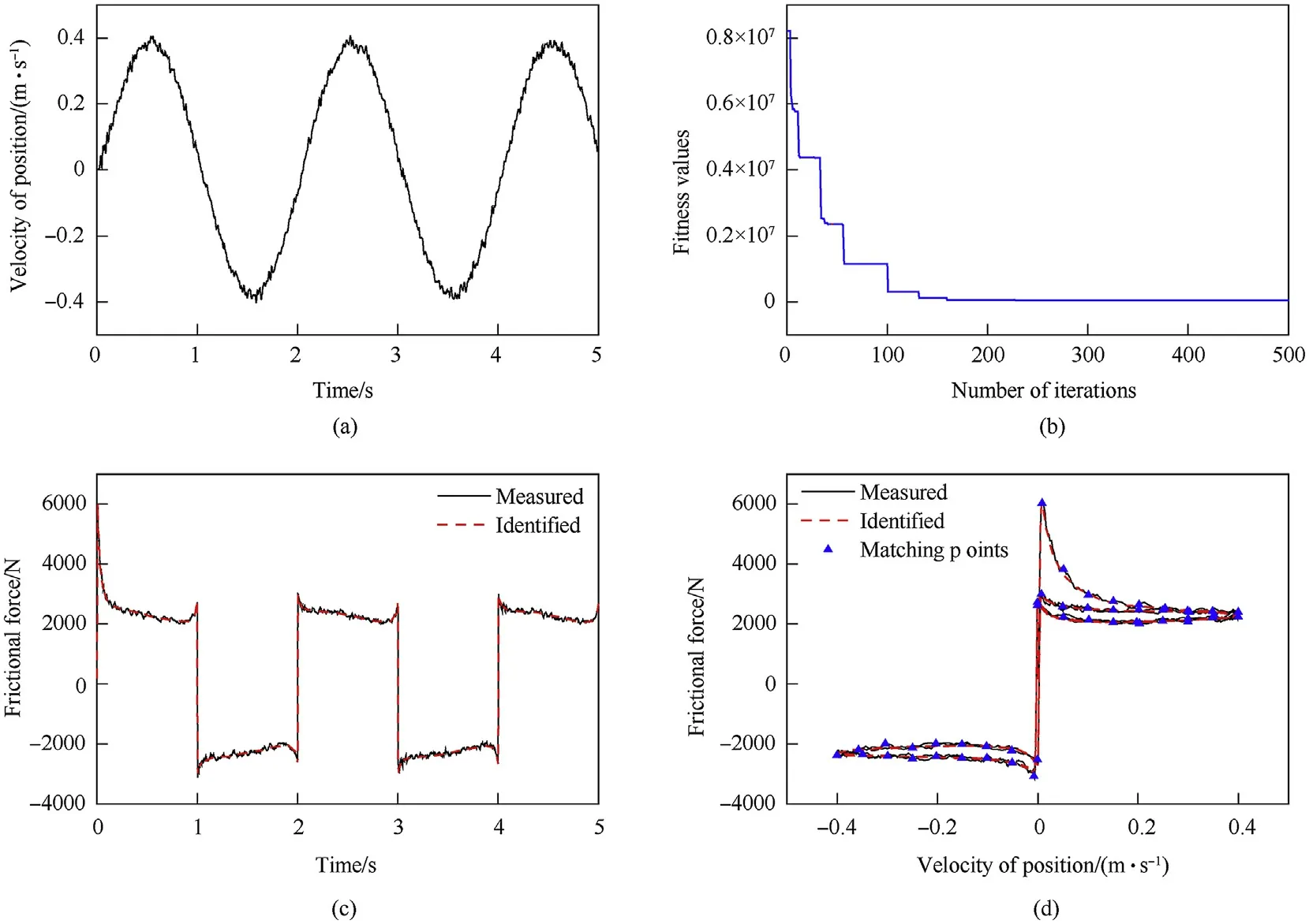
Fig. 7. Test data and identification results: (a) velocity variation of cylinder, (b) convergence curve, (c) friction force-time curve, and (d) friction force-velocity curve.

Fig. 8. Contact force X direction in different models: (a) model proposed in this paper; (b) model established by ADAMS; (c) model proposed in Ref. [2].

Fig. 9. Contact force Y direction in different models: (a) model proposed in this paper; (b) model established by ADAMS; (c) model proposed in Ref. [2].

Fig.10. Angle curve calculated by different models: (a) model proposed in this paper; (b) model established by ADAMS; (c) model proposed in Ref. [2].

Fig.11. Angular velocity curve calculated by different models: (a) model proposed in this paper; (b) model established by ADAMS; (c) model proposed in Ref. [2].
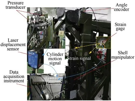
Fig.12. Dynamic response testing system of shell manipulator.
5.2. Experimental verification
In order to further verify the effectiveness of the model presented here in the real system, a test system for the shell manipulator was built, as shown in Fig.12, and a relevant experimental study with and without shell loads was carried out. The working pressures of the plus and minus chambers of the hydraulic cylinder were measured by pressure sensors.The displacement of the piston was acquired by a laser sensor when conducting the friction parameter identification tests.The velocity and acceleration of the piston were obtained by the first and second differentiations of the displacement, respectively. To improve the quality of differential signal, the nonlinear tracking-differentiator method [58] has been used. In addition, the noises in the calculated velocity andacceleration signal were filtered by a Butterworth low-pass filter with a bandwidth of 80 Hz. The angle signal of the hub (2) was recorded by an angle encoder. Strain gauges were attached to the center of the lower side of flexible beams (1) and (2).

Table 5 Test instrument and related parameters.
The strains were collected by the data acquisition instrument,which represented the flexible deformation at the sticking point of the strain gauges. For convenience, only the strain measured at flexible beam 1 is discussed below.The control system and control strategy were the same as the actual device,and the information of the test sensors is shown in Table 5.
In the simulation analysis, the radial clearance was the median of the fit tolerance (c= 0.025 mm), the axial clearance cwas 0.1 mm,other parameters were assigned according to the attributes of the 3D model, as detailed in Table 2. The centers of both hubs were assumed to coincide with the corresponding journal centers at the initial moment.The initial angles of the hubs corresponding to the global coordinate system were -180. To eliminate the influence of early unstable collisions caused by the initial position uncertainty, the stabilization time of 0.2 s was added to the simulations,that is,the hydraulic cylinder began to move after 0.2 s.The pressures of the two chambers of the hydraulic cylinder were assigned according to the value measured in the experiment. The mathematical relationship between the elastic displacement and the strain at the measuring point can be expressed as follows:

where d is the distance from the measuring point to the neutral layer, v is the elastic displacement, φ(x) and q(t) are modal functions of and modal coordinates of the measuring point,respectively.
Dynamic responses of the luffing motion of the shell manipulator without and with loads are shown in Figs.13-15.The bearing center locus in the radial plane and the components of the contact forces in both revolute clearance joints are shown in Figs.16-19.
Fig.13 shows that the simulation and experimental results of the rotation angle were similar. The maximum errors of the rotation angle between the simulations and experiments were 0.2and 0.5under the no-load and load conditions,respectively.In addition,the time histories of the angular velocity and the errors between the simulations and experiments are plotted in Fig. 14; the angular velocities of the simulations generally agree with the experimental values.
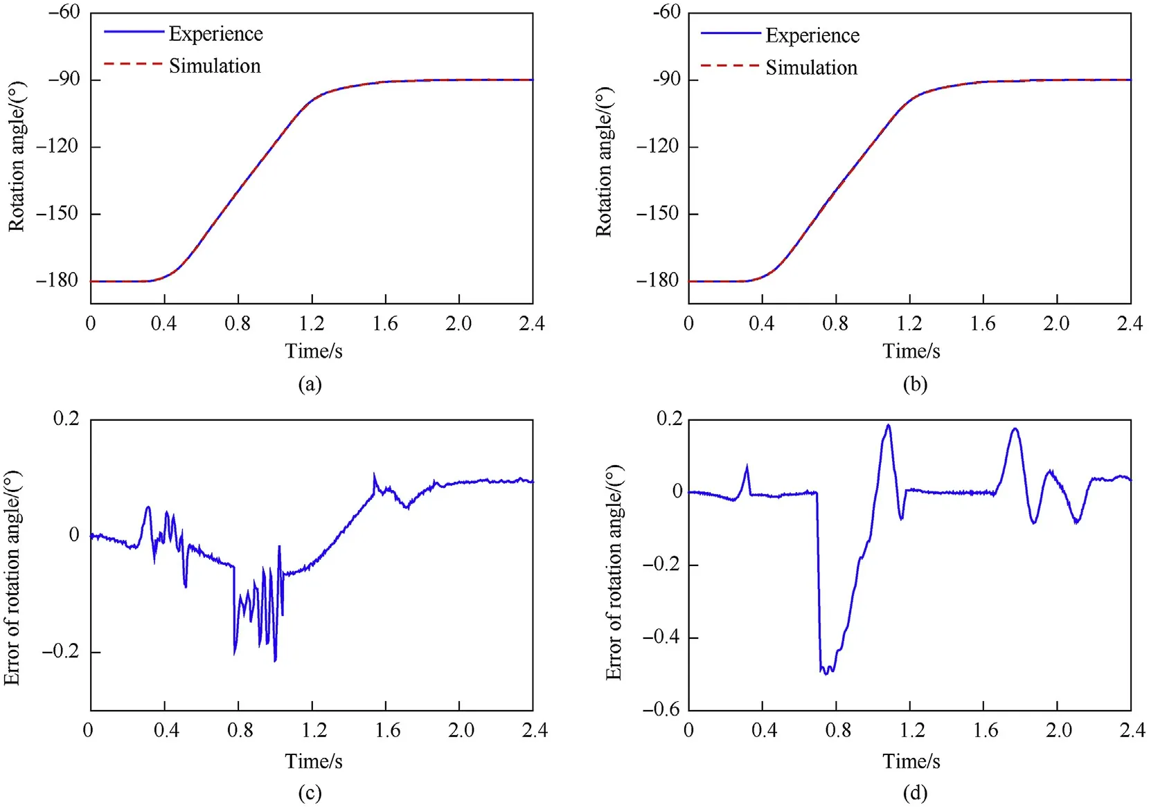
Fig.13. Rotation angle of the shell manipulator and the errors between the simulation and experiment:(a) rotation angle under no-load conditions, (b) rotation angle under load conditions, (c) error of rotation angle under no-load conditions, and (d) error of rotation angle under load conditions.
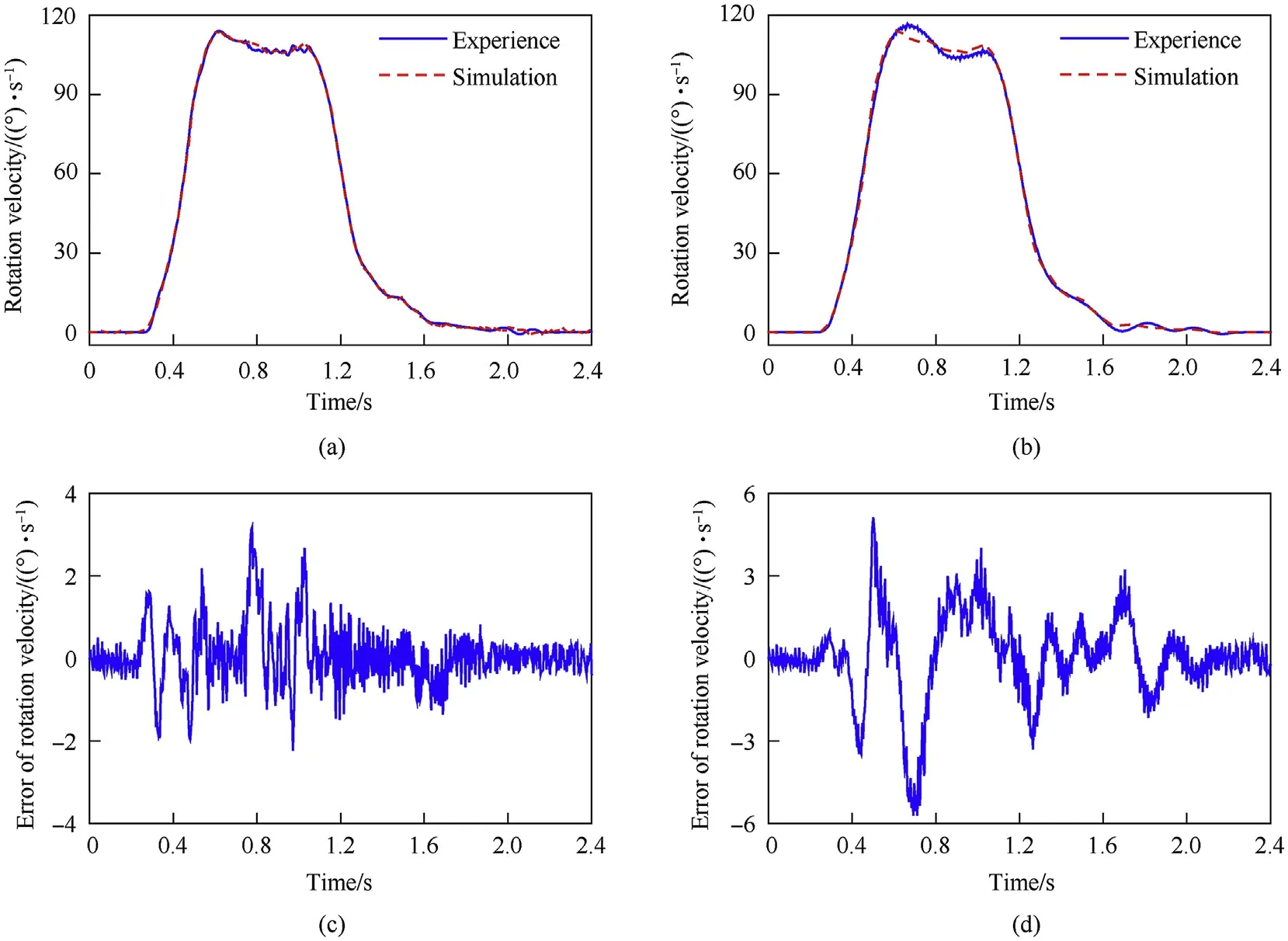
Fig.14. Rotational velocity of the shell manipulator and the errors between the simulations and experiments under no-load and load conditions:(a) rotational velocity under noload conditions, (b) rotational velocity under load condition, (c) errors of rotational velocity under no-load conditions, and (d) errors of rotational velocity under load conditions.
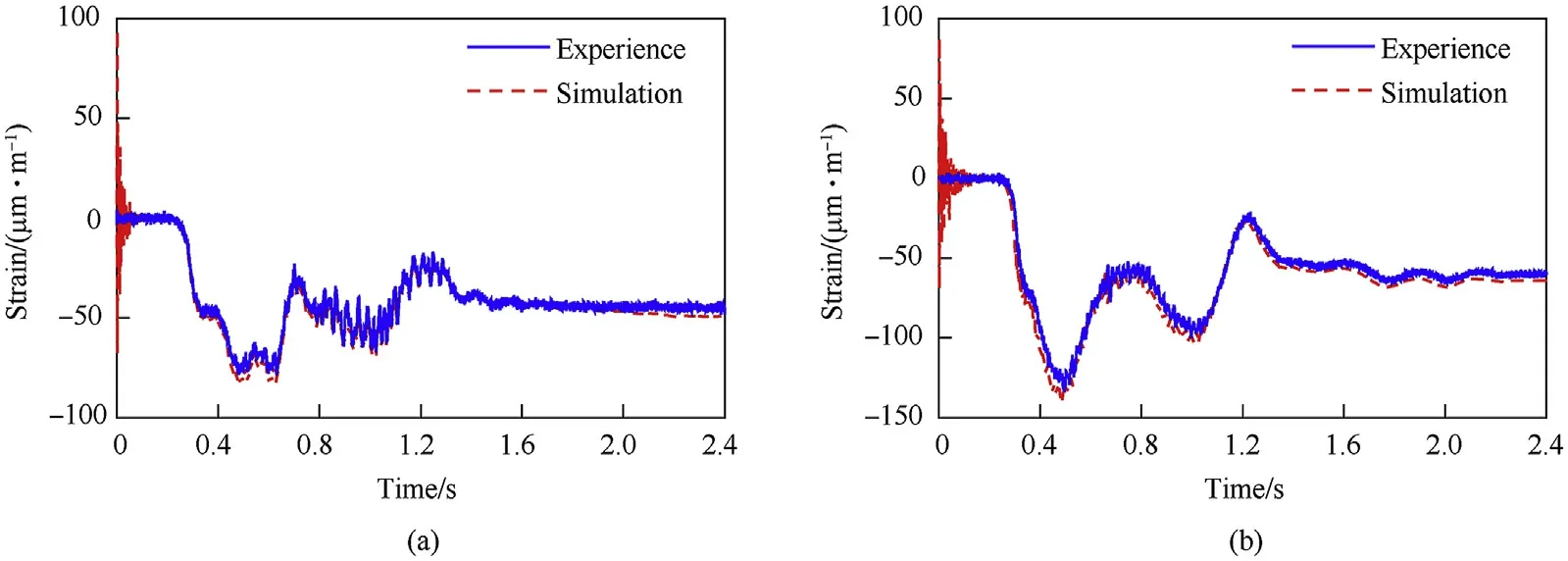
Fig.15. Strain of flexible beam under no-load and load conditions: (a) under no-load conditions and (b) under load conditions.
The strains at the measuring point of flexible beam (1) with or without a load are illustrated in Fig.15.There was a large deviation between the strain values obtained by the simulations and tests within 0.2 s. The reason was that the initial position of the hub bearing in simulation can’t match the actual situation exactly.This leads to frequent and sharp variations of the contact force between the bearing and the journal,which affects the elastic displacement of the flexible beam.However,after 0.2 s,the simulated strain was close to the strain obtained by the experiment.
As shown in Figs.16 and 17, the bearing of the left hub always maintained contact with the journal after several transitions between the contact state and free-flight state.However,the bearing of the right hub changed motion states between contact and free flight for a long time and maintained contact with the journal after 0.7 s.The penetration depth of the left revolute clearance joint was larger than the right revolute clearance joint. The penetration depth of both the revolute clearance joints with a load was greater than that without a load.
Figs.18 and 19 show that the value and duration of contact force in the axial direction were far less than those in the radial direction.However,the amplitude variation of the contact force in the vertical direction was significantly greater than that in the horizontal direction in the radial plane. As illustrated in the partial enlarged drawing of the contact force, the radial force still fluctuated after the shell manipulator was in the set position.This occurred because the stored energy was transferred in the elastic components mutually.
The above comparisons between the simulation and experimental results demonstrated that the proposed model for the shell manipulator was reasonable and effective, and it further indicated the accuracy of the friction parameter identification results.
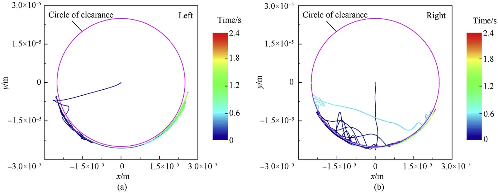
Fig.16. Bearing center locus in radial plane under no-load conditions: (a) left clearance joint and (b) right clearance joint.
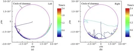
Fig.17. Bearing center locus in radial plane under load conditions: (a) left clearance joint and (b) right clearance joint.
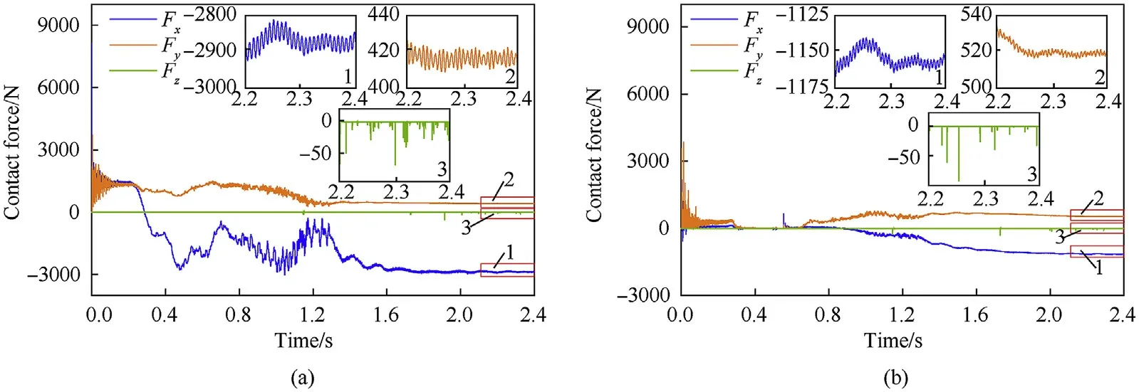
Fig.18. Contact forces of clearance joint without load: (a) left clearance joint and (b) right clearance joint.
6. Effect of parameters on dynamic response
6.1. Effect of clearance size
In this section, the dynamic characteristics of the shell manipulator under different clearance sizes, 0.025, 0.1, 0.5 mm, are examined. The other parameters in the simulation were the same as those in the experimental verification (see Section 5.2). The tip displacement and velocity of the shell manipulator under different clearances and their corresponding errors from the design clearance(0.025 mm)are shown in Fig.20,and the radial contact forces of the clearance joints on both revolute joints with different clearance sizes are plotted in Fig. 21.
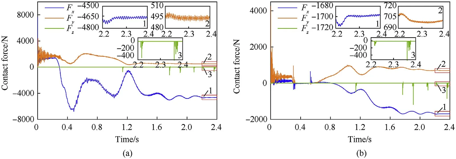
Fig.19. Contact forces of clearance joint with load: (a) left clearance joint and (b) right clearance joint.
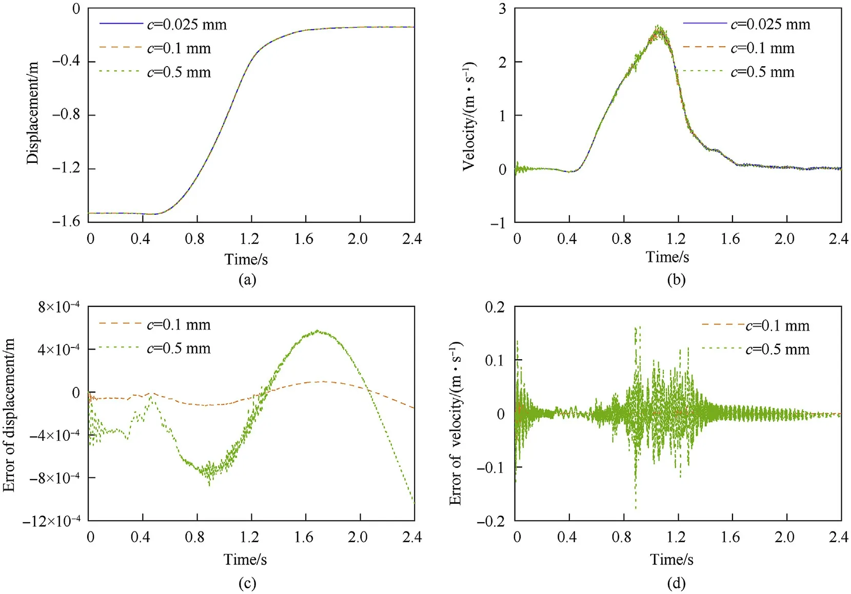
Fig.20. Tip displacement of shell manipulator under different clearance sizes and the errors relative to the design clearance:(a)displacement,(b)velocity,(c)displacement errors,and (d) velocity errors.
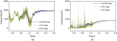
Fig. 21. Contact forces of revolute clearance joint under different clearance sizes: (a) left clearance joint and (b) right clearance joint.

Fig.22. Tip displacement of shell manipulator with different stiffnesses and the errors relative to the design stiffness:(a)displacement,(b)velocity,(c)displacement errors,and(d)velocity errors.
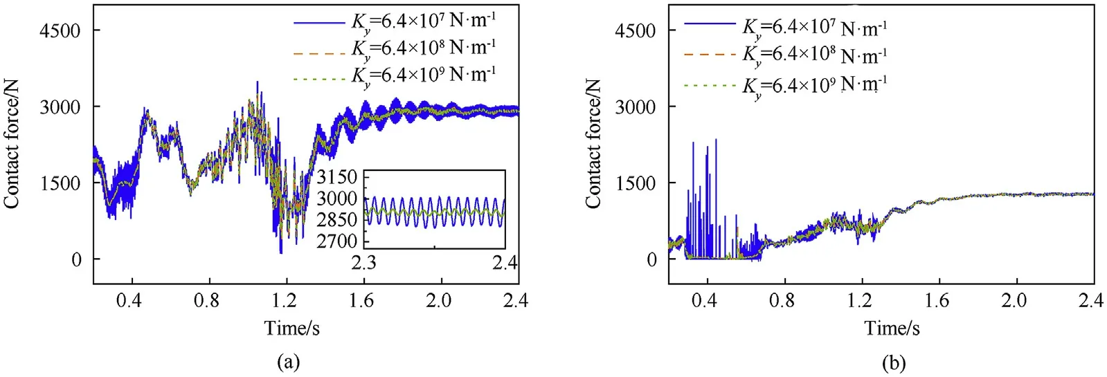
Fig. 23. Contact forces of clearance joint under different stiffness: (a) left clearance joint and (b) right clearance joint.
Fig. 20 shows that the deviation errors of the tip displacement and velocity increased as the clearance increased, and the velocity was more sensitive than the displacement to the clearance. From the trend of the deviation errors of the tip displacement and velocity,it can be deduced that the deviation errors in the initial stage were caused by the different distances between the initial position and the contact point under different clearance sizes. The large variations of the errors were mainly due to angular deviations of the shell manipulator with different clearance sizes. As shown in Fig.21,with the increase in the clearance size,the peak value of the contact force increased, and the fluctuation of the contact force became more violent. When the clearance values were 0.025, 0.1,and 0.5 mm,the maximum contact forces of the left clearance joint were 3253, 3650, and 3811 N, respectively, and the maximum contact forces of the right clearance joint were 1283, 1670, and 4478 N, respectively. The contact force of the left clearance joint was always greater than zero after the hydraulic cylinder was actuated.It indicated that the bearing and the journal remained in contact at the left clearance joint. Therefore, the increase in the clearance size will not lead to a large collision force of the left clearance joint but will lead to a huge impact force on the right clearance joint, which revealed that a heavy load imposed on the clearance joint was conducive to the stability of the contact state.
6.2. Effect of stiffness of cylinder support
To investigate the influence of the stiffness of the cylinder support on the dynamic characteristics of the shell manipulator,different types of stiffnesses were considered. For the sake of conciseness,only the influence of Y-axis stiffness was discussed in this paper, because the influence of stiffness on Y-axis is significantly larger than other two axes under gravity environment. The other parameters in the simulation were the same as those in the experimental verification (see Section 5.2). The tip displacement and velocity of the shell manipulator for different stiffnesses and the corresponding errors from the design stiffness(6.4×10N/m)are shown in Fig.22,and the radial contact forces of the clearance joints on rigid hubs with different clearances are plotted in Fig.23.
As illustrated in Fig. 22, when the stiffness dropped from the design stiffness, the errors of the tip displacement and velocity increased. The velocity was more sensitive than the displacement.However, when the stiffness increased from the design stiffness,the effect on the dynamic response was slight.The tip displacement and velocity underwent periodic oscillations after the angle of the shell manipulator achieved the set value. This indicated that the errors were mainly caused by the elastic deformation of the flexible body. Analogously, when the stiffness dropped from the design stiffness, as plotted in Fig. 23, the peak value of the contact force increased, and the fluctuations of the contact force became more violent. This indicated that the increase in the stiffness had little influence on the dynamic characteristics of the system when the stiffness of the cylinder support was greater than the design stiffness, whereas the decrease in the stiffness will produce a large change of the dynamic response.
7. Conclusion
In this study,an improved computational model is proposed to describe the motion characteristics of a hydraulically driven shell manipulator with revolute clearance joints, which takes the influence of the joint clearance, the elastic deformation of the rotating beam, and the dynamic behavior of the hydraulic cylinder into account.A first-order rigid-elastic coupling model and Timoshenko beam theory are adopted to simulate the deformations of shell manipulator. A modified contact force model was developed to simulate the physical properties of realistic revolute joints of shell manipulator with small clearances, heavy loads, and damping coefficients with variations of the indentations.The coupled equation of motion of the cylinder and the flexible beam was derived based on length control method, in which the nonlinear friction characteristics of cylinder are considered.
Through the comparison with former research and experimental result, the effectiveness and accuracy of the proposed model were validated. The proposed method has several superiorities compared with other similar studies: (a) it effectively guarantees the convergence of the computation under high rotational speed and larger deformation of beam; (b) the scope of the application in the restitution coefficient and clearance size of the collision object are enlarged especially in case of conformal contact conditions with lower clearance values;(c)the proposed approach provides a novel way to establish the luffing motion of hydraulically driven manipulator with clearance,which has high computational precision and efficiency.
Based on the improved computational model, the influences of different clearance sizes and stiffnesses of the cylinder support on the dynamic characteristics of the shell manipulator were studied.The simulation results showed that the clearance size had a significant effect on the dynamic behaviors of the shell manipulator.The increase in the clearance size led to an increase in the position error and generated a huge impact force of the clearance joint.When the stiffness of the cylinder support decreased from the design stiffness, the position errors and contact force became larger.However,the increase in the stiffness will have a significant influence on the motion characteristics of the shell manipulator after the stiffness exceeds the threshold value.
The authors declare that they have no known competing financial interests or personal relationships that could have appeared to influence the work reported in this paper.
This work was supported by the National Natural Science Foundation of China [grant number 11472137] and the Fundamental Research Funds for the Central Universities[grant numbers 309181A8801, 30919011204].
- Defence Technology的其它文章
- Research on DSO vision positioning technology based on binocular stereo panoramic vision system
- Blast performance of layered charges enveloped by aluminum powder/rubber composites in confined spaces
- Chemical design and characterization of cellulosic derivatives containing high-nitrogen functional groups: Towards the next generation of energetic biopolymers
- Applicability of unique scarf joint configuration in friction stir welding of AA6061-T6: Analysis of torque, force, microstructure and mechanical properties
- Multi-area detection sensitivity calculation model and detection blind areas influence analysis of photoelectric detection target
- Accurate analysis of limiting human dose of non-lethal laser weapons

