Strategy of Barrel Roll and Decoy Deployment Against Infrared Air-to-Air Missile
ZHANG Nan,CHEN Changsheng,SUN Jingguo,LIANG Xuechao
〈制导与对抗〉
Strategy of Barrel Roll and Decoy Deployment Against Infrared Air-to-Air Missile
ZHANG Nan1,CHEN Changsheng1,SUN Jingguo1,LIANG Xuechao2
(1.,710065,;2.,100076,)
Evasive maneuvers and decoy deployment are effective measures against infrared (IR) air-to-air missiles for fighters.In this study, both aspects were considered: barrel roll maneuver and unpowered point source decoys.For practical purposes, the interference process, movement characteristics, and influence mechanism of the decoy on the missile guidance system are expounded, in which the conditions needed for the barrel roll maneuver and the force of the decoy are considered.In addition, the air-to-air missile is assumed to adopt the true proportional navigation law or augmented proportional navigation law, and the decoys are launched in the conventional mode or emergency mode.Linearized time-varying models and adjoint models for barrel roll maneuvers with decoy deployment influence on missile guidance precision are established.The correctness of these models was verified by a simulation result analysis and comparison.The miss distance is an important parameter for characterizing the performance of an air-defense missile.The average miss distance and percentage of maximum miss distance were proposed to analyze the adjoint model results.Based on the work mentioned above, the barrel roll rate and the transition step maneuver angle of the target aircraft, as well as the simultaneous launch quantity, the period between successive launches, and launch direction policy on the miss distance are analyzed to provide strategic references for fighters against IR air-to-air missiles.
adjoint method, decoy launch, evasive maneuver, IR air-to-air missile, miss distance, proportional navigation law
0 Introduction
Compared with radar air-to-air missiles, infrared (IR) air-to-air missiles have a strong anti-interference ability and high hit rate and are widely used in air combat.History suggests that almost 90% of all downed aircraft between 1979 and 1993 were destroyed by IR-homing missiles.In addition, 14 out of 22 airplanes (78%) were downed by IR homing missiles during the First Gulf War[1].IR air-to-air missiles are the most effective short-range air combat weapons.Therefore, it is necessary to study countermeasures against IR air-to-air missiles.
Short-range IR air-to-air missiles mainly pursue the target using proportional navigation (PN)[2-3]or its modified forms[4-5].PN has been widely used in engineering because of its straight terminal trajectory, small overload, strong robustness, and high precision.PN can be used as long as line-of-sight (LOS) can be acquired.PN guidance laws can be categorized into two major classes[6].The first is missile velocity referenced PNs, which mainly include pure proportional navigation (PPN) and its variants, where the commanded acceleration is perpendicular to the missile velocity.Suwon Lee et al.[7]performed a statistical analysis of the missile’s capture region for pure proportional navigation guidance considering target maneuvers.LI Kebo et al.[8]proposed a guidance strategy with impact angle constraints based on PPN and the interception performance was demonstrated through numerical simulation examples.Satadal Ghosh et al.[9]proposed a composite proportional navigation guidance law using a combination of standard pure proportional navigation and the retro-proportional navigation guidance laws for intercepting higher speed non-maneuvering targets at specified impact angles in three-dimensional engagements.The second class of PNs is LOS referenced PNs, including true proportional navigation (TPN) and its variants.The performance of 3D TPN against an arbitrarily maneuvering target was thoroughly analyzed using the Lyapunov-like approach by LI Kebo et al.[10], and, the upper bound of the 3D LOS rate and the commanded acceleration of the 3D TPN were obtained.Feng Tyan[11]analyzed the capture area of general 3D TPN guidance laws using a novel method.A more practical capture region of the realistic true proportional navigation guidance law for an arbitrarily maneuvering target was analyzed by BAI Zhihui et al.[12].The direction of the TPN’s commanded acceleration was perpendicular to the LOS, and its magnitude was only proportional to the LOS rate.When aiming at a maneuvering target, if the target maneuver compensation is added to the proportional navigation, it is called augmented proportional navigation (APN).According to the optimal control theory, it can be proved that PN is the optimal solution of the linear guidance problem that minimizes the square integral of the control quantity without considering the target's maneuvers or the dynamic delay of the guidance system.APN is the optimal guidance navigation for a maneuvering target with a constant overload.The missiles used in this study were considered to have adopted these two guidance laws.
The target aircraft mainly avoids attacks from IR air-to-air missiles by implementing tactical maneuvers[13]and IR interference[1,14].The numerically obtained three-dimensional optimal evasive maneuvers of a fighter against a proportional navigation missile are those of the vertical-S type and horizontal-S type[15], which are two-dimensional in nature.The barrel roll maneuver is regarded as an approximation of these optimal maneuvers; however, the barrel roll maneuver is easier to implement than the optimal maneuvers[16].The barrel roll maneuver is an effective maneuvering form[17].
According to the radiation characteristics of IR decoys, the decoys can be divided into point source decoys and surface decoys.According to their motion characteristics, IR decoys can be divided into unpowered, aerodynamic, self-propelled, towered, and air-launched decoys.Most research on IR decoys focuses on compositions[18], simulations[19], IR target recognition algorithms[20- 21], and so on.This paper focuses on the deployment policy of the unpowered point source decoy considering the influence on the missile miss distance from the guidance point of view, and thus, target recognition is reasonably simplified.
In terms of research methods, the adjoint method is widely used for missile modeling and simulation, performance evaluation, precision analysis of guidance system, and other problems such as target allocation.Among them, Martin Weiss et al.introduced the adjoint method for state space models[22], hybrid guidance loop state-space models[23]and two-phase guidance loop models[24].LI Quancheng et al.[25]presented three seeker blind range guidance policies with different guidance precisions using the adjoint method.Several computationally efficient weapon target-allocation algorithms for assigning defenders to missiles in a cooperative interception scenario were developed by Vitaly Shalumov et al.[26].Domenic Bucco and Martin Weiss[27]used the adjoint method to study the influence of the blind range of seekers on missile guidance.Timo Sailaranta et al.[17]established a simple model of the target barrel roll maneuver, and validated its rationality using the adjoint method.However, none of the above studies considered the influence of decoy deployment on the miss distance of the missiles.WANG Weiqiang et al.[28]proposed a guidance precision analysis method for the entir process of air countermeasures from infrared decoy deployment, identification, and guidance disturbance to the final miss distance calculation.Arthur Vermeulen et al.[29]used the adjoint method to study the influence of the target maneuver and decoy interference on the miss distance of the missile and provided corresponding countermeasures; however, they studied the two-dimensional maneuver of the target and did not consider the effect of the decoy force.Huang Hesong et al.[30]established the movement and radiation models of target maneuver and surface-type decoy based on real data, and the best defense strategy was analyzed when the missile came from the front of the aircraft, however there was little work on a multi-decoy deployment policy.
In this study, considering the interference process, movement characteristics, and influence mechanism of the decoy on the missile guidance system, mathematical models to study the tactical strategy of the target barrel roll maneuver and decoy deployment against an infrared air-to-air missile were proposed based on the adjoint method.The main contributions of this study are as follows:
1) The model built in this study comprehensively considers the barrel roll maneuver and decoy deployment, which are closer to the actual situation, and fully validates the model.The modeling method can provide a reference for other maneuver forms and decoy deployment research.
2) Maneuver and decoy deployment strategies are usually studied from an experimental point of view, which requires a large amount of work and lacks regularity.In contrast, computational efficiency can be improved, and more rules can be found with the introduction of the adjoint method.
3) The target and decoy of this study are built in an absolute coordinate system, which can not only can model and analyze the conventional deployment mode but also the emergency deployment mode.
4) The miss distance is considered an important index of missile combat performance.The average miss distance and percentage of maximum miss distance, which considers the occurrence probability of time-to-go, are proposed to analyze the results of the adjoint model.
The remainder of this paper is organized as follows.The decoy interference processes are described in Section 1.The linearized time-varying models and adjoint analysis models for barrel roll maneuvers with decoy deployment influence on the missile guidance precision are established in Section 2.Section 3 presents model validation, simulation results, and analysis.Finally, conclusions are presented in Section 4.
1 Description and modeling of decoy interference process
The classical decoy interference process in this study is described as follows: when the decoy is launched, a radiation source similar to the target IR characteristic is generated in the seeker's field of view.Without loss of generality, we can assume that the LOS of the missile is no longer aimed at the target, but at the power centroid of the target and the decoys until the target has been identified.This type of interference is called power centroid interference.Suppose that the position, velocity, and acceleration for the i-th decoy in the seeker field of view are (Di,Di), (Dyi,Dzi) and (Dyi,Dzi), respectively.While (T,T), (Ty,Tz) and (Ty,Tz) are the position, velocity, and acceleration of the target, respectively.Tdenotes the radiation intensity of the target.Then, the positionC, velocityCyand accelerationCyof the power centroid in the-direction can be calculated as:
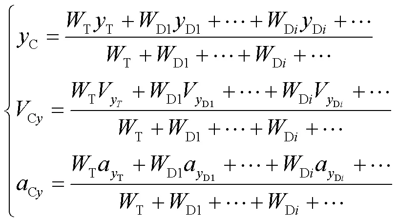
The corresponding physical quantity of the power centroid in the-direction is similar to that in(1).The technical parameters involved include simultaneous launch quantity, the period between successive launches, and launch direction policy.
The missile anti-interference process can be described in three phases[29], as shown in Fig.1.

Fig.1 The process of air-to-air missile anti-interference
In the missile's terminal guidance, the seeker locks and tracks the target and the target launches the decoy att.The decoy ignites and leaves the target, as shown in Fig.1 (a), corresponding to the first phase.The lateral position of the decoy is consistent with that of the aircraft; however, their lateral accelerations and velocities are different.Because the missile seeker cannot instantaneously discriminate between the decoy and target, the seeker tracks the power centroid, that is, the false target.With the movements of the decoy and target, the false target moves away from the aircraft, and the seeker tracks it during the period of timettot,as shown in Fig.1(b), corresponding to the second phase.After the discrimination time, the seeker has successfully discriminated the target through the anti-interference algorithm of the seeker att, which means the missile begins to track the target (assuming that the target is still in the seeker's field of view) and the aiming point instantly shifts back to the target, as shown in Fig.1(c) corresponding to the third phase.If the target has already left the seeker’s field of view, then the seeker will lose the target, which is not discussed in this paper.In the figure,MandTrepresent the constant velocities of the missile and target, respectively.crepresents the closing speed of the missile and the target.For the head-on scenario,c=M+T,and for tail chase,c=M-T.For simplicity, the initial value of the LOS angle was taken as zero, that is,=0.The time-to-gogo=F-, whereFis the final time of the engagement corresponding to the minimal miss distance andis the current flight time.The distance between the missile and the target,, is given by the product ofcandgo.MandTare taken as the maneuver overloads of the missile and target, respectively.Ddenotes the decoy velocity.DCb,DCbandDCbare the suddenly shifted values of the displacement, velocity, and acceleration of the power centroid, respectively, att.
To induce an IR-guided air-to-air missile effectively, the radiation intensity of the decoy is always designed to be higher than the IR radiation intensity of the aircraft.The ratio of the decoy radiation energy to the target radiation energy in the dynamic state, that is, the suppression coefficient, is generally between 2 and 3.It can be considered that the intensity of the IR radiation source formed by multiple decoys launched by the target in each group is the sum of the radiation intensity of every single decoy.Here, we consider the radiation intensity of the decoy to be the same and equal toD.Thus,can be calculated as
=D/T(2)
2 Models of Target Maneuver and Decoy Deployment Influence on Missile
2.1 Model of target maneuver
The model described in [17] considers that the aircraft barrel roll maneuver has a certain normal velocity, however the normal situation is that the target aircraft is in a cruising state; that is, the target is in a uniform straight flight state when the missile is launched.The target first implements a step-transition maneuver that utilizes the rated overload capacity, then the barrel roll will be implemented.Fig.2 shows a schematic of the barrel roll maneuver.The maneuver was as follows: the target flew with a circular motion in the plumb plane and moved at a uniform speed along the axle of the barrel roll.The origin of the coordinate system is the barrel roll axis.
0anddenote the initial phase angle and the barrel roll rate, respectively.The initial velocity of the target barrel rollR=T/=T/, and the time spent on the step maneuver isstep=R/T=1/.0=0+p/2 is the angle of the step maneuver.Ty,Tz,Ty, andTzare the overload and acceleration values of the target in theanddirections, respectively, which can be calculated during the step maneuver as follows:

Whereas overload and acceleration value of target during barrel roll can be given by

According to the definition in Fig.2 and the origin of the coordinate system, the initialandcoordinates of the targetsT0andT0are

And the position of the target in the simulation can be calculated as

The target maneuver can then be transformed into a pulse input function, and the acceleration in the Y-direction is shown in Fig.3.
2.2 Model of IR decoy
The decoy is primarily affected by gravity and aerodynamic drag.The kinematic equations are as follows[30]:
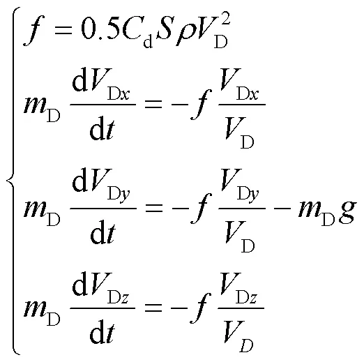
whereis the atmospheric density and,d,,D,Dare the drag force, drag coefficient, windward area, mass, and velocity of the decoy, respectively.Dx,Dy,Dzdenote the components of the missile velocity in the coordinate system shown in Fig.2, andis the gravitational acceleration.This paper discusses the initial velocity of the decoy in the barrel roll maneuver, which can be calculated as follows:

whereFis the launch velocity of the decoy relative to the target aircraft, which is positive when the decoy is launched to the outer side of the circular motion; otherwise, it is negative.denotes the angle for the barrel roll maneuver during decoy launch.
Taking the-direction as an example, a decoy model was established, and the-direction is similar.To facilitate modeling, the decoy accelerationDyis considered to be constant in the second phase of Fig.1.The specific calculation is as follows:

whereDyaandDybare the velocities of the decoy in the-direction attandt, respectively.Certainly,t=t-tis the significant time of the decoy, that is, the identification time required by the anti-interference algorithms of the seeker.
2.3 Calculation model of miss distance for IR decoy in conventional launch mode
The conventional launch mode of the IR decoy considered here refers to the launch mode with a period of successive launches not less than thet.Other parameters include the simultaneous launch quantity n and the launch direction policy.In actual combat situations, the quantity, direction, and speed of every decoy causes a difference in the discrimination time of the seeker.In this study, it is assumed that the seeker needs another fixed time to discriminate the real target whenever a new decoy appears in the seeker field of view.By analyzing the anti-interference process of the IR air-to-air missile, as shown in Fig.1, in the absence of velocity pointing deviation and initial displacement deviation, the influence model of the power centroid under the barrel roll maneuver on the missile miss distance is shown in Fig.4.
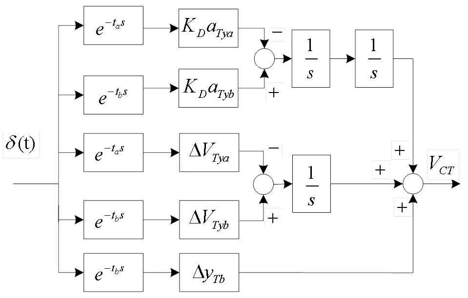
Fig.4 Influence model of power centroid under barrel roll
In Fig.4,D=/(+1) is the sudden shift value andCTdenotes the influence of the target maneuver on the power centroid velocity when the decoy works.According to (1), the effect of the target on the acceleration of the power centroid is decreased byDtimes at t, and the effect is increased byDtimes att.Because of the time delay link, the initial phase of the sinusoidal signal needs to be adjusted according to (9) to ensure consistency with the phase at the moment of acceleration shift.

DTyarepresents the velocity shift value of the power centroid caused by the target maneuver att, whereasDTybandDTbrepresent the velocity and displacement shift values attrespectively, which can be calculated as

whereTyarepresents the velocity of the target attandTybandTbrepresent the velocity and position of the target at t, respectively.When multiple groups of decoys are launched, the velocity and absolute displacement of the target at each discrimination time can be calculated in advance using (5) to avoid the individual calculation for each module and reduce the complexity of the model.
The motion characteristics of the decoy when launched without maneuvering are shown in Fig.5.
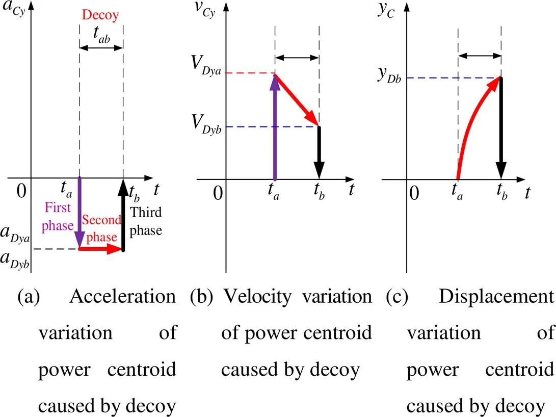
Fig.5 The process of decoy interference
In Fig.5, the decoy is launched attand discriminated attusing the anti-interference algorithm of the seeker.Dbrepresents the position of the decoy att.In the first phase (t), it can be considered that the position of the decoy coincides with the IR radiation source of the target, however the acceleration and velocity of the power centroid change.The acceleration shift valueDDyaand velocity shift valueDDyacaused by the decoy can be calculated using (12).During the second phase (t-t), because the acceleration of the power centroid caused by the decoy is considered to be constant before, the velocity changes linearly and the displacement changes parabolically.In the last phase (t),DDyb,DDyb, andDDbdenote the acceleration, velocity, and position shift value of the power centroid caused by decoy, respectively, att, and they can be expressed as follows:

Therefore, the linearized model of the power centroid under decoy interference can be expressed as an impulse function, as shown in Fig.6.In this figure,CDrepresents the effect of the decoy on the velocity of the power centroid.
2.4 Calculation model of miss distance for IR decoy in emergency launch mode
The emergency launch mode means that the target will launch decoys intensively with a period of successive launches less than thet.Because thetis generally small, for the convenience of modeling analysis, it is assumed that the period of successive launches ist/2.As previously assumed, when a new decoy appears in the seeker’s field of view, the seeker needs another timetto discriminate the real target.It is assumed thattafter launch, every decoy will be out of the seeker’s field of view or have been eliminated by the anti-interference algorithm.Consequently, the power centroid calculation does not consider these eliminated decoys.The power centroid moves toward the target after the new decoy launches; however, based on previous assumptions, the seeker will continue aiming at the power centroid consisting of the target and multiple new decoys.The seeker will not discriminate the real target for a long period of time, and this increases the discrimination difficulty because of the lack of target information accumulation.Therefore, it is necessary to study the influence of emergency launch mode on the missile miss distance.Table 1 shows the weight coefficients of the power centroid at the time of the first row in the emergency launch mode, so the sum of the coefficients in every column is 1.1,2,3, and4are the weight coefficients of the power centroid and can be calculated as follows:


Table 1 Weight coefficients of power centroid
The target launches the first group decoys atstep, and no more than three groups of decoys should be considered when calculating the power centroid.The parameters shown in Table 1 are the weight coefficients of the target and decoy in the power centroid calculation at each time step; therefore, the shift value of each time can be calculated by using the weight coefficients of the current column minus the former ones.We can then establish a mathematical model of the emergency launch mode based on the conventional launch mode.
2.5 Linearized model of IR air-to-air missile


If the missile adopts TPN, the direction of the missile overload command is vertical to that of the LOS and can be stated as

If the missile can estimate the target acceleration value and adopts APN, the overload value of the guidance law outputAPNcan be expressed as:


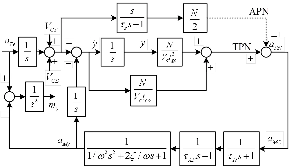
Fig.7 Linearized model of air-to-air missile
Using the superposition principle, taking the-direction as an example, combined with the calculation module shown in Fig.4 and Fig.6, a linearized model of the target barrel roll maneuver with decoy deployment influence on the missile is established, as shown in Fig.7.N,AP,M,andare the signal processing time constant, autopilot time constant, airframe response angular velocity, damping ratio, and proportional navigation coefficient of the missile, respectively.
2.6 Establishment of adjoint analysis model
According to the criterion for establishing the adjoint model of the linearized system[4], the adjoint analysis model of the target barrel roll and decoy launch influence on the missile was established.The adjoint form of the time-delay link is itself.The model in this study uses a time-forward simulation to calculate the required parameters of the adjoint model, which can avoid complicated case discussion and parameter derivation, as well as to aid the research on more complex maneuvers, continuous maneuvers, and multiple decoy launches.
There are three inputs in the model shown in Fig.7; therefore, the miss distance in the-direction,m, is the sum of the three outputs.Similarly, the miss distance in the-direction (m) can be acquired, and the miss distanceallcan be expressed as:

For the multi-decoy case, the shift value calculation module can be connected in parallel with the missile adjoint model at the corresponding time.Furthermore, through one simulation of the adjoint method, we can obtain the results of the time-forward system, which needs to be simulated many times; that is, the calculation efficiency is greatly improved.
3 Simulation and analysis
3.1 Time-forward model validation
Compared with the adjoint model, each variable of the time-forward simulation model has a clear physical significance and is easy to follow.Therefore, the time-forward simulation model was validated by taking the barrel roll maneuver and one decoy launch for the TPN missile as an example.The simulation conditions are listed in Table 2.The acceleration changes in the power centroid induced by the target and decoy, the acceleration of the target, and the power centroid are shown in Fig.8, and the corresponding velocity and position changes are shown in Fig.9 and 10.At 0.4s, the target implements a barrel roll maneuver and launches decoys towards the outside of the circular motion at the same time; meanwhile, the acceleration, velocity, and displacement of the power centroid induced by the maneuver become 1/3 of the target.At 0.8s, the seeker discriminates the real target, and the physical quantities curve of the power centroid coincides with the target later.All these simulation results match the expected results.

Table 2 Simulation parameters

Fig.8 Acceleration change of the power centroid and the target in the Y-direction

Fig.9 Velocity change of the power centroid and the target in the Y-direction

Fig.10 Position change of the power centroid and the target in the Y-direction
3.2 Time-forward simulation and adjoint simulation results validation
All decoys are launched towards the outside of the circular motion, and the time-forward simulation time varies from 0.2s to 7s with an interval of 0.2s.It can be seen from Fig.11 that the time-forward simulation and the adjoint simulation miss distance exactly coincide, which verifies the correctness of the adjoint model.
3.3 Simulation results of decoy launch during target barrel roll maneuver
The target launches decoys during the barrel-roll maneuver process.The initial mass of a typical decoy is 0.3kg, the mass consumption rate is 0.04kg/s, the windward areais 0.003m2, drag coefficientdis 0.35, the combustion time is 5s, and the launch speed is 30m/s, which is launched upward vertically relative to the target.At the beginning of the simulation, the attitude angles of the target aircraft were all 0°, the flight altitude was 4 km, the overload was 6g, the speed is 0.8Ma, and the barrel roll rate was 2rad/s.Then, the velocity of the decoy can be obtained.The position of the decoy can be obtained by integrating the velocity.The phase angle of the target barrel roll varied from 0° to 300° at intervals of 60°.Theplane trajectory diagram and change in velocity versus time are shown in Fig.12.The position, velocity, and acceleration of the decoy launched at each moment with different initial phase angles of the barrel roll maneuver were calculated.

Fig.11 Miss distance comparison for time-forward simulation and adjoint simulation
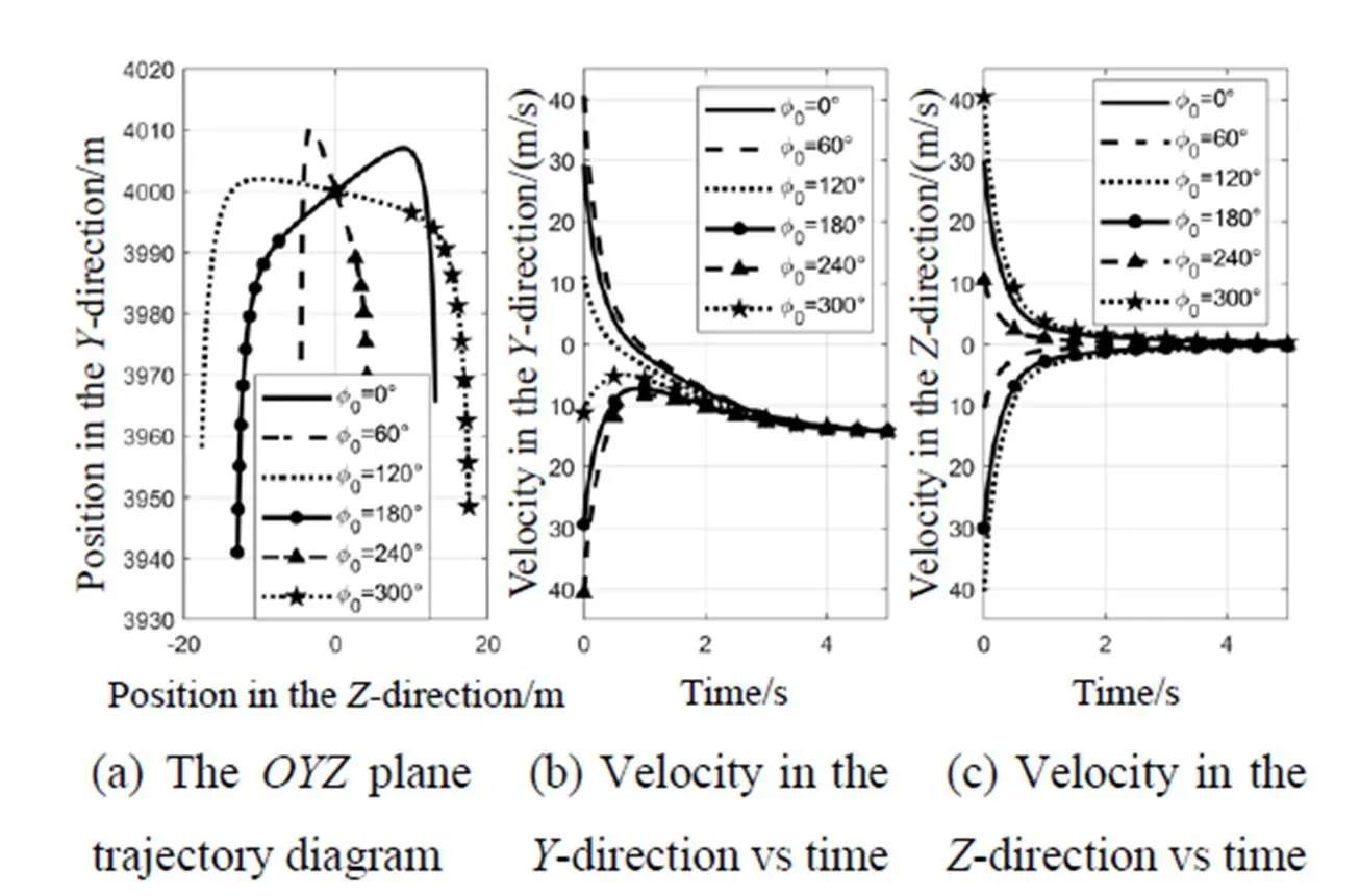
Fig.12 The trajectory diagram and the change of velocity vs time
3.4 Analysis of miss distance affected by barrel roll
1) Effect of barrel roll rate on miss distance for TPN and APN missiles
The barrel roll ratevalues studied were 1, 1.5, 2, 3and 4rad/s with different associated barrel diameters.The missile was a tail chase on the target, and the remaining simulation parameters were set as listed in Table 2.The influence of the barrel roll rate on the miss distance of the missile was studied.The variation in the missile miss distance versusgois shown in Fig.13.

Fig.13 The variation curves of miss distancevstgo for different barrel roll rates


wheremaxrepresents the maximumgoandm(go) represents the miss distance corresponding togo, as shown in Fig.14 (a).Meanwhile the concept of namely the percentage of the maximum miss distance[25]pfor the-th curve can be calculated as:


Fig.14 Analysis of the average miss distance and the percentage of the maximum miss distance
where max(go) represents the maximum miss distance of all curves corresponding togo, as shown in Fig.14(b).Assuming that the probability of eachgounder real airborne combat condition is equal, combined with thegoestimation error[32], the higher value means that there will be a greater survival probability.If the average miss distance varies slightly, more useful information can be obtained through the percentage of the maximum miss distance.
It can be seen from Fig.13 that to make the miss distance generated by the TPN-and APN-guided missiles sufficiently large, the barrel roll maneuver should be performed whengois greater than 2s, and the aircraft should try to put the missile behind the tail to increasego.By combining Fig.13 and Fig.14, it can be concluded that with the same barrel roll rate, APN will produce a higher miss distance than TPN.However, when the barrel roll rate is small, the average miss distances of the two guidance laws are not significantly different, nevertheless the TPN will produce a higher miss distance with a higher probability.TPN generates the maximum average miss at approximately 2rad/s, and APN generates the maximum average miss at 3rad/s.
2) The influence of initial phase angle of barrel roll maneuver on missile miss distance
The barrel roll rate is set to 2.5rad/s and decoys are launched vertically upward relative to the target.Two decoys were launched simultaneously with a launch period of 0.6s.The average miss distance and the percentage of maximum miss distance corresponding to the initial phase angle of the target barrel roll maneuver are shown in Fig.15.It can be seen that the average miss distances change only slightly with0in this simulation.When0is 0°, the TPN guidance law has the highest percentage of maximum miss distance, whereas when0is 120° and 220°, the TPN guidance law has the highest percentage of maximum miss distance.

Fig.15 Average miss distance and percentage of maximum miss distance vs initial phase angle of barrel roll maneuver
3.5 Analysis of the influence of decoy parameters on miss distance during barrel roll maneuver
1) The influence of simultaneous launch quantity on miss distance
The parameters of the decoy launch and barrel roll rate were set as shown in Fig.12 and 15.The other parameters are the same as those shown in Fig.13.The initial phase angle of the barrel roll maneuver was 0°.The suppression coefficient for one decoy was set to 2, and the suppression ratiofor the simultaneous launch quantitydecoys was 2.The variation curve of the miss distance versusgois shown in Fig.16, where=0 indicates that no decoy was launched.
As shown in Fig.16, for the two types of guidance laws, more simultaneous launches lead to higher missile miss distances.Comparing the curves in the figure, the decoy launch generates a higher miss distance than merely implementing barrel roll; however, with the increase in quantity, the miss distance growth tendency decreases.Furthermore, because of the limited quantity of decoys carried on the aircraft and the fact that there are generally multiple missile attacks during airborne combat, the simultaneous launch quantity should not be set higher than two or three due to economic and efficacy concerns.

Fig.16 Miss distance vstgofor different simultaneous launch quantity
2) The influence of the period between successive launches and launch direction policy on missile miss distance
The most practical deployment of decoys is to launch them at a certain rate[29].The group time intervals for conventional launch mode are from 0.5s to 2.1s with an interval of 0.2s, while for emergency launch mode it is set to 0.2s.The simultaneous launch quantity is 2, and the barrel roll rate is 2.5rad/s.Here, considering four policies, decoys are launched in the same directions for the first two policies, while for each of the other two policies, decoys are launched in reverse directions.The first group of decoys for the first and third policies are launched towards the outside of the circular motion, whereas for the other two policies, decoys are launched towards the inside.The remaining simulation conditions were the same as those shown in Fig.15.The launch speeds of all the decoys were the same, and the initial phase angle of the barrel roll was 0 °.The average miss distance of the missile in the emergency launch mode is shown in Table3; the influence on the miss distance under different launch policies in the conventional launch mode is shown in Fig.17.
By comparing Table 3 and Fig.17, it can be seen that the emergency launch mode generates a higher average miss distance, which is likely to cause the target to fly out of the seeker field of view to complete the escape.

Table 3 The average miss of missile in the emergency launch mode
4 Conclusions
In this study, a realistic target barrel roll maneuver model, decoy launch model, and adjoint analysis model were established for missile guidance accuracy.The influence of the target barrel roll maneuver and IR decoy on the miss distance of the IR-guided missile was studied.After the missile warning system issues an alarm signal, the target should place the missile behind the tail and implement a step maneuver with the maximum overload.When the velocity condition is reached, the target will perform the barrel roll maneuver with a roll rate of approximately 2 rad/s for TPN-guided missiles and with a roll rate of approximately 3 rad/s for APN-guided missiles.Currently, the aircraft launches decoys outside of the circular motion.The proposed simultaneous launch quantity is 2 or 3, and the period between successive launches should be less than 1s.If necessary, an emergency launch mode can be implemented for great effect.This study has significance in providing guidance on target maneuvers and decoy launches for evading IR-guided missiles.
[1] Raghav Harini Venkatesan, Nandan Kumar Sinha.Key factors that affect the performance of flares against a heat-seeking air-to-air missile[J].:,,, 2014, 11(4): 387-401.
[2] Giovanni Franzini,Luca Tardioli, Lorenzo Pollini, et al.Visibility augmented proportional navigation guidance[J].,,, 2018, 41(4): 983-991.
[3] XU Yang, FANG Yangwang, WU Youli, et al.Proportional guidance intelligent regulation strategy under the infrared interference and maneuvering[J]., 2019, 41(3): 137-145.
[4] Paul Zarchan.[M].the 6th, AIAA, 2012.
[5] WANG Xiaohai, MENG Xiuyun, ZHOU Feng, et al.Sliding mode guidance law with impact angle constraint based on bias proportional navigation[J]., 2021, 43(5): 1295-1302.
[6] LI Kebo, LIANG Yangang, SU Wenshan, et al.Performance of 3D TPN against true-arbitrarily maneuvering target for exoatmospheric interception[J]., 2018, 61(8): 1161-1174.
[7] LEE Suwon, LEE Youngjun, LEE Seokwon, et al.Data-driven capturability analysis for pure proportional navigation guidance considering target maneuver[J]., 2021,22(5): 1209-1221.
[8] LI Kebo, LIAO Xuanping, LIANG Yangang, et al.Guidance strategy with impact angle constraint based on pure proportional navigation[J]., 2020, 41(S2): 724277.
[9] Satadal Ghosh,Debasish Ghose, Soumyendu Raha.Composite guidance for impact angle control against higher speed targets[J].,,, 2016, 39(1): 98-117.
[10] LI Kebo, LIANG Yangang, SU Wenshan, et al.Performance of 3D TPN against true-arbitrarily maneuvering target for exoatmospheric interception[J]., 2018, 61(8): 1161-1174.
[11] FENG Tyan.The capture region of a general 3D TPN guidance law for missile and target with limited maneuverability[C]//, 2001: 512-517.
[12] BAI Zhihui, LI Kebo, SU Wenshan, et al.Capture region of RTPN guidance law against arbitrarily maneuvering targets[J]., 2020, 41(8): 323947.
[13] SHI Zhenqing, LIANG Xiaolong, ZHANG Jiaqiang, et al.Modeling and simulation analysis of 3-D air-to-air missile attack zone under the condition of target maneuvers[J]., 2019, 39(3): 97-106.
[14] Ernst-Christian Koch.Review on pyrotechnic aerial infrared decoys[J]., 2011, 26(1): 3-11.
[15] Ilan Rusnak.Bounds on the root-mean-square miss of radar-guided missiles against sinusoidal target maneuvers[J]., 2011, 34(4): 1066-1069.
[16] Fumiaki Imado and Sachio Uehara.High-g barrel roll maneuvers against proportional navigation from optimal control viewpoint[J]., 1988, 21(6): 876-881.
[17] Timo Sailaranta, Ari Siltavuori, Antti Pankkonen.Simple missile models against high-g barrel roll maneuver[C]//, 2011: 01-12.
[18] Ernst Christian Koch, Arno Hahma, Volker Weiser, et al.Metal-Fluorocarbon Pyrolants.XIII: High performance infrared decoy flare compositions based on MgB2and Mg2Si and polytetrafluoroe-thylene/viton[J]., 2010, 35: 1-7.
[19] Srinivasan Ramaswam, David A Vaitekunas, Willem H Gunter, et al.Improvements to the ShipIR/NTCS adaptive track gate algorithm and 3D flare particle model[C]//+, 2017, 10178: 1-12.
[20] LI Shaoyi, ZHANG Kai, YIN Jianfei, et al.Study on IR target recognition approach in aerial jamming environment based on bayesian probabilistic model[J]., 2019, 7: 50300-50316.
[21] SHI Chen.Research on target recognition for anti-jamming towards infrared decoys[D].Chengdu: University of Electronic Science and Technology of China, 2020.
[22] Martin Weiss.Adjoint method for missile performance analysis on state space models[J]., 2005, 28(2): 236-248.
[23] Martin Weiss, Domenic Bucco.Adjoint method for hybrid guidance loop state-space models[J]., 2015, 38(4): 614-622.
[24] Martin Weiss, Domenic Bucco.Evaluation method for dual phase guided weapons based on the adjoint method[C]//, 2007: 1-12.
[25] LI Quancheng, FAN Yonghua, WAN Shizheng, et al.Influence of the seeker blind range guidance policy on guidance precision[C]//9(CYBER), 2019: 1120-1124.
[26] Vitaly Shalumov, Tal Shima.Weapon–target-allocation strategies in multiagent target–missile–defender engagement[J]., 2017, 40(10): 2452-2464.
[27] Domenic Bucco and Martin Weiss.Blind range influence on guidance loop performance: an adjoint-based analysis[C]//, 2013: 1-16.
[28] WANG Weiqiang, JIA Xiaohong, FU Kuisheng, et al.Guidance precision analysis based on airborne IRCM stochastic process[J]., 2019, 41(2): 163-170.
[29] Arthur Vermeulen, Gerrit Maes.Missile avoidance maneuvres with simultaneous decoy deployment[C]//, 2009: 1-17.
[30] HUANG Hesong, TONG Zhongxiang, LI Taorui, et al.Defense strategy of aircraft confronted with IR guided missile[J]., 2017, 2017: 1-9.
[31] Hecht C.Homing guidance using angular acceleration of the line of sight[C]//, 1991: 856-869.
[32] Satadal Ghosh,Debasish Ghose, Soumyendu Raha.Unified time-to-go algorithms for proportional navigation class of guidance[J]., 2016, 39(6): 1188-1205.
基于桶滚机动和诱饵投射的红外空空导弹对抗策略研究
张 楠1,陈长胜1,孙靖国1,梁雪超2
(1.中国航空工业计算所,陕西 西安 710065;2.中国运载火箭技术研究院,北京 100076)
机动规避和投射诱饵是战斗机对抗红外空对空导弹的有效措施。本文主要从桶滚机动和无动力型点源诱饵两方面进行了对抗策略研究。为了使研究更具实用性,在考虑桶滚机动所需条件和诱饵弹受力的前提下,阐述了诱饵弹的运动特性、干扰过程和对导弹制导系统的影响机理。为使研究更具适用性,本文假设空对空导弹采用真比例导引律或增广比例导引律,并且诱饵考虑在常规模式和应急模式下投射。建立了桶滚机动并伴有诱饵投射时对导弹制导精度影响的线性化时变模型和伴随模型。同时,通过仿真结果的分析与比较,验证了模型的正确性。脱靶量是表征防空导弹性能的一个重要参数,提出了平均脱靶量和最大脱靶量占比来分析伴随模型的仿真结果。在此基础上,分析了目标机的桶滚机动角速率和过渡机动方位角以及诱饵弹的齐投数量、投射间隔与投射方向策略对导弹脱靶量的影响规律。这将为战斗机对抗红外空对空导弹提供策略参考。
伴随法;诱饵投射;机动规避;红外空空导弹;脱靶量;比例导引律
TJ765.3
A
1001-8891(2022)03-0231-13
date:2021-08-02;
date:2021-09-23.
ZHANG Nan (1987-), Male, Xi'an Shaanxi, Master degree, Mainly engaged in the research of avionics bus network and guidance.E-mail: 550100308@qq.com.

