
A synergy establishment by metal-organic framework and carbon quantum dots to enhance electrochemical water oxidation
2022-03-14 09:30QiuxingMouXunWngZhenhngXuPnurZulErleiLiPingpingZhoXinghiLiuHouinLiGongzhenCheng
Chinese Chemical Letters 2022年1期
Qiuxing Mou,Xun Wng,Zhenhng Xu,Pnur Zul,Erlei Li,Pingping Zho,∗,Xinghi Liu,∗,Houin Li,∗,Gongzhen Cheng
aSchool of Printing and Packaging,Wuhan University,Wuhan 430072,China
bCollege of Chemistry and Molecular Sciences,Wuhan University,Wuhan 430072,China
ABSTRACT Available online Integrating transition metal centered MOFs with conductive materials is a feasible route to enhance electron transfer efficiency of materials.Herein,a composite porous structure CQDs10@NiFe-MOF-A was fabricated via introducing carbon quantum dots(CQDs)into porous NiFe-MOF.The CQDs would make partial loss of lattice in MOF during its growth,leading to the composite building block with the coexistance of crystalline region and amorphous region.The calcining treatment would produce an ultrathin protective layer as well as some lattice collapse.The synergy effect between NiFe ions effectively regulated electronic structure of metal active sites,and successful grafting of CQDs to NiFe-MOF significantly improved electrical conductivity.As expected,the catalyst exhibited outstanding OER performances with high mass activity of 91.6 A/g at overpotential of 300 mV and robust durability of 10,000 cycles in 1 mol/L KOH,which outperformed that of noble catalyst IrO2 of 25.2 A/g.The strategy paves a feasible and effective avenue for the non-noble metal catalysts.
Keywords:Metal-organic framework Carbon quantum dots Electrochemical impedance spectroscopy Oxygen evolution reaction Stability
With the continuous depletion of fossil fuels and deteriorating environmental issues,there is unprecedented demand for clean energy.Hydrogen is considered a promising alternative to fossil fuels due to its high energy density and environmental friendliness[1,2].Electrochemical water splitting provides a sustainable strategy for hydrogen productionviaconverting electricity generated from renewable resources(e.g.,solar,wind,tidal)into a storable form[3].However,the sluggish kinetics of the half reaction oxygen evolution reaction(OER)becomes the bottleneck for energy conversion efficiency and power output,severely hindering its largescale applications and industrial production[4].Currently,noble metal oxides(RuOx/IrOx)are still preferred for OER but limited by their scarcity and low economic efficiency[5].Therefore,in the past decades,great efforts have been devoted to explore low-cost,earth-abundant,and high catalytic property non-precious metal catalysts such as transition metal-based materials and their derivatives,and carbon-based materials[6,7].
Metal-organic frameworks(MOFs)are a new class of crystalline microporous materials with periodic network structure formed by organic ligands and metal ions through orderly self-assemble,which feature unique advantages such as adjustable porosity,high specific surface area,diverse metal centers and synergy[8,9].MOFs have risen intense attention in many fields like gas storage or separation,catalysis,sensing and drug delivery[10].In recent years,an increasing number of studies have been conducted to explore the potential of MOFs in catalysts due to their uniform active metal site distribution and accessible pore channels,which is a promising platform for catalysis[9].Unfortunately,the inherent electrical insulating properties of MOFs fundamentally hinder their application in electrocatalysis[11].Therefore,finding suitable methods to improve the electrical conductivity is of great importance for developing the electrocatalytic properties of MOF-based materials[12].
Carbon quantum dots(CQDs)are new carbon nanomaterials with sizes less than 10 nm,which can be synthesized by topdown and bottom-up methods[13].Different synthesis methods result in different functional groups on the surface,which facilitates their compounding and doping with different materials.As electron acceptors,carbon quantum dots can substantially improve the electron transfer efficiency and electrocatalytic activity of materials when they are doped into solid-phase carriers or modified by self-doping[14].Thus,the effective combination of CQDs and MOFs paves a practicable avenue for enhancing OER activity.
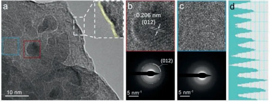
Fig.1.(a)TEM images of CQDs10@NiFe-MOF-A,inset in(a):enlarged TEM image of the boundary.(b,c)High-resolution TEM images and corresponding SAED in(a).(d)Contrast intensity profile of(b).
Herein,we reported a kind of transition metal porous MOF doped with carbon quantum dots CQDs10@NiFe-MOF-A,which was integrated by a hydrothermal treatment and followed by a low-temperature calcination to augment amorphization.The wellcombined catalyst featured homogeneous active sites and high specific surface area,and the synergistic effects between inherent OER catalysis of porous MOF and good conductivity of CQDs endowed the as-prepared sample considerable OER performances and robust durability,reaching a current density of 10 mA/cm2with overpotential of 289 mV at ultra-low loading mass,and exhibiting robust durability for 10,000 CVs and 30,000 s chronoamperometrical test.X-ray photoelectron spectroscopy(XPS)and Bode phase plots indicate that the intrinsic high catalytic activity from NiFe porous MOF and largely enhanced electroconductivity caused by the homogeneous and proper doping of CQDs all contribute to the outstanding OER performances.
The fabrication of the CQDs10@NiFe-MOF-A with an advanced OER performance was designed through a two-step synthesis strategy as shown in Fig.S1 and Experimental section(Supporting information).First,a one-pot solvothermal method was used to obtain CQDs10@NiFe-MOF,in which CQDs were embedded uniformly into the MOF matrix.Second,a low-temperature calcination process was carried out to obtain the target catalyst CQDs10@NiFe-MOF-A with less crystalline,where the “A” represented amorphous property.Scanning electron microscopy(SEM)images in Fig.S2(Supporting information)showed the as-prepared CQDs10@NiFe-MOF featured the nanoparticles clusters with particle diameters distributed from tens to hundreds of nanometers.After lowtemperature calcination,the morphology of CQDs10@NiFe-MOF-A did not change significantly,retaining the characteristics of nanoclusters,as shown in Fig.S3a(Supporting information).The TEM image of CQDs10@NiFe-MOF-A in Fig.S3b(Supporting information)confirmed a granular structure composed of randomly aggregated nanoparticles.A certain part was selected randomly to get its enlarged image,as shown in Figs.S3c and S4(Supporting information).It can be seen that the CQDs with about 10 nm size distributed in the MOF uniformly and firmly(such as the yellow circle).More details can be got in the high-resolution TEM(HRTEM)in Fig.1a.The MOF was equipped with an about 1 nmthick nanolayer on the outer wall,which was speculated to be a metal oxide layer formed by the low-temperature calcination.The surface was rugged,which was favorable to the exposure of reactive sites and the contact between catalysts and electrolyte.In the inner part,the CQDs was wrapped with the matrix closely.The functional groups(like–NH2,–OH,–COOH)in the CQDs combined well with MOF via chemical bonds,making a higher electron transfer efficiency.Fig.1b gave a lattice distance of 0.206 nm,as shown in Fig.1d,which is identical to the(012)plane of the carbon(PDF#50-1083).The further structural information of CQDs was given by the selected area electron diffraction(SAED)in Fig.1b,where the bright spots can be indexed to the(012)plane and also certified the carbon structure,which illustrated the successful introduction of CQDs.The SAED pattern of the blue box in Fig.1c displayed diffused rings,indicating the amorphous nature of the selected area of the MOF matrix,which may be induced by the lattice distortion caused by the introduction of CQDs and the excalation of lattice water during low-temperature calcination,and it was beneficial to the generation of more effective active sites.Meanwhile,recognizable lattice fringes were found in some other areas,as shown in Fig.S5(Supporting information),the HRTEM and corresponding fast Fourier transform(FFT)image in selected region testified its partial-order structure.Thus,we believed that the crystalline and amorphous regions coexist in such hierarchical composite,which guaranteed for the efficiency of electron transfer during OER.Fig.S3d(Supporting information)showed that the four elements C,O,Ni and Fe were evenly distributed in the CQDs10@NiFe-MOF-A.Hence,the as-prepared catalyst was qualified for the high OER catalytic efficiency and strong durability.
Powder X-ray diffraction(PXRD)was used to further investigate the evolution of structural characterization of these samples.The XRD patterns in Fig.2a exhibited almost the same positions with a few differences among these catalysts.NiFe-MOF showed the highest peak intensity among these samples,which indicated its maximum crystallinity by the well-ordered lattice growth.After the doping of CQDs,the peak intensity of CQDs10@NiFe-MOF showed a slight decline,which was caused by the introduction of CQDs into the MOF matrix that decreased crystallinity.Moreover,the peaks at 2θ=12.73°,33.40° and 59.31° disappeared,which might be because the introduced CQDs hindered partial lattice growth of NiFe-MOF in those directions[11].To verify this conjecture,control sample CQDs10-NiFe-MOF was made by integrating equivalent amount CQDs with the as-formed NiFe-MOF by another solvothermal treatment.XRD pattern of the CQDs10-NiFe-MOF showed the peaks maintained well in the same position as NiFe-MOF,proving the correctness of the above hypothesis.Compared with CQDs10@NiFe-MOF,the peaks in CQDs10@NiFe-MOF-A displayed lower intensity especially at 2θ=11.78°,demonstrating the decreased crystallinity due to the lattice water loss and partial collapse of MOF lattice arose from low temperature calcination,and this treatment can increase the number of defects and thus enhance OER performance of the catalysts[15].
N2absorption was used to infer the structure of these catalysts.As shown in Fig.2b,the three isotherms performed a type-IV isotherm with typical H3 hysteresis loop,which was often observed in structure with slit-like mesopores and caused by the unevenness surface of MOF and accumulation of nanoparticles[16,17].The BET analysis gave specific surface areas of 26.1,38.7 and 36.3 m2/g,and total pore volume of 0.066,0.085 and 0.109 cm3/g for NiFe-MOF,CQDs10@NiFe-MOF,and CQDs10@NiFe-MOF-A,respectively,indicating the introduction of CQDs brought an increase in pore volume and a basic maintenance on surface area.The similar isotherms illustrated that the doping of CQDs and calcination did not impose a significant effect on the large-scale structure,which was well-fitted with the SEM results.Subtle differences can be observed in the isotherms atP/P0>0.8,where the isotherm of CQDs10@NiFe-MOF-A presented a smaller curvature,demonstrating more mesopores were formed in the matrix by the calcinations[11].In the inset of Fig.2b,the pore width distribution of the three samples exhibited they all equipped with mesopores at about 3.5 nm,which ensured the porous structure.Overall,CQDs doping has increased the surface area of the samples,further calcination did not change the value significantly,but influenced the pore volume.
Thermogravimetric analysis(TGA)was measured from 40 °C to 1000 °C under oxygen atmosphere to verify the successful implementation of the low-temperature calcination.The curves in Fig.2c told us that the CQDs10@NiFe-MOF-A had a slight advantage in thermostability over the uncalcined counterpart,which was reflected by its slower falling curve and more residual weight after TGA test.This was resulted of the simple short-time calcination treatment at 160 °C during the fabrication of CQDs10@NiFe-MOFA.Thus,the CQDs10@NiFe-MOF-A exhibited a delayed decline in weight loss from the initial temperature to about 160°C(inset in Fig.2c),owning to the partial loss of lattice water,and a moredefective catalyst and enhancement in catalytic performance can be expected.
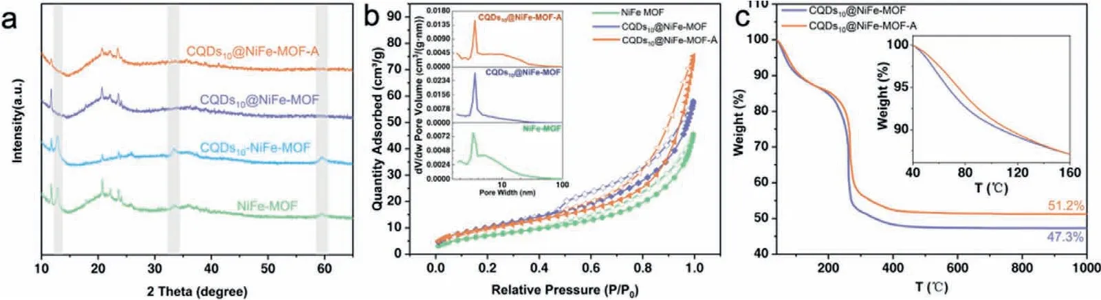
Fig.2.Characterization of the catalysts.(a)XRD,(b)N2 absorption-desorption isotherms,inset:pore width distribution.(c)TGA,inset:enlarged region from 40 °C to 160 °C.
To investigate the chemical states and electronic interactions of the main elements,X-ray photoelectron spectroscopy(XPS)was applied and analyzed.Survey patterns of the three samples of NiFe-MOF,CQDs10@NiFe-MOF and CQDs10@NiFe-MOF-A in Fig.S6(Supporting information)showed the signal of C,O,Ni and Fe can be observed.The high-resolution XPS spectra of C 1s,O 1s,Ni 2p and Fe 2p were shown in Fig.S7(Supporting information),where the curve I,II,III represented NiFe-MOF,CQDs10@NiFe-MOF and CQDs10@NiFe-MOF-A,respectively.The C 1s spectra in Fig.S7a can be fitted to the peaks centered at 284.8,286.0 and 289.4 eV,which can be assigned to C=C,C-N,and -COOH species,respectively[18].The O 1s spectra in Fig.S7b can be deconvoluted into three contributions,531.8 eV(O1),532.6 eV(O2),and 533.7 eV(O3),respectively,which was given rise to the signal of lattice oxygen,hydroxyl group(-OH),and water molecule absorbed[19].The curves of Ni 2p for the three samples in Fig.S7c showed the main peak of Ni 2p3/2located at around 857.0 eV,confirming the formation of highly oxidized state Ni3+[20],while the main peak for Fe 2p3/2centered at about 709.0 eV implied that Fe existed in the form of +2/+3(Fig.S7d)[21].Notably,compared to the bare NiFe-MOF and doped CQDs10@NiFe-MOF,a negative shift of~0.1 eV(for Ni)and a positive shift of~0.6 eV(for Fe)can be observed for the CQDs10@NiFe-MOF-A electrode,indicating the electronic structure of Ni and Fe have been modulated by lattice disorder caused by low-temperature calcination treatment,and it certified the strong electronic interactions between the Ni/Fe metal active centers,which is favorable for water oxidation[19,22].
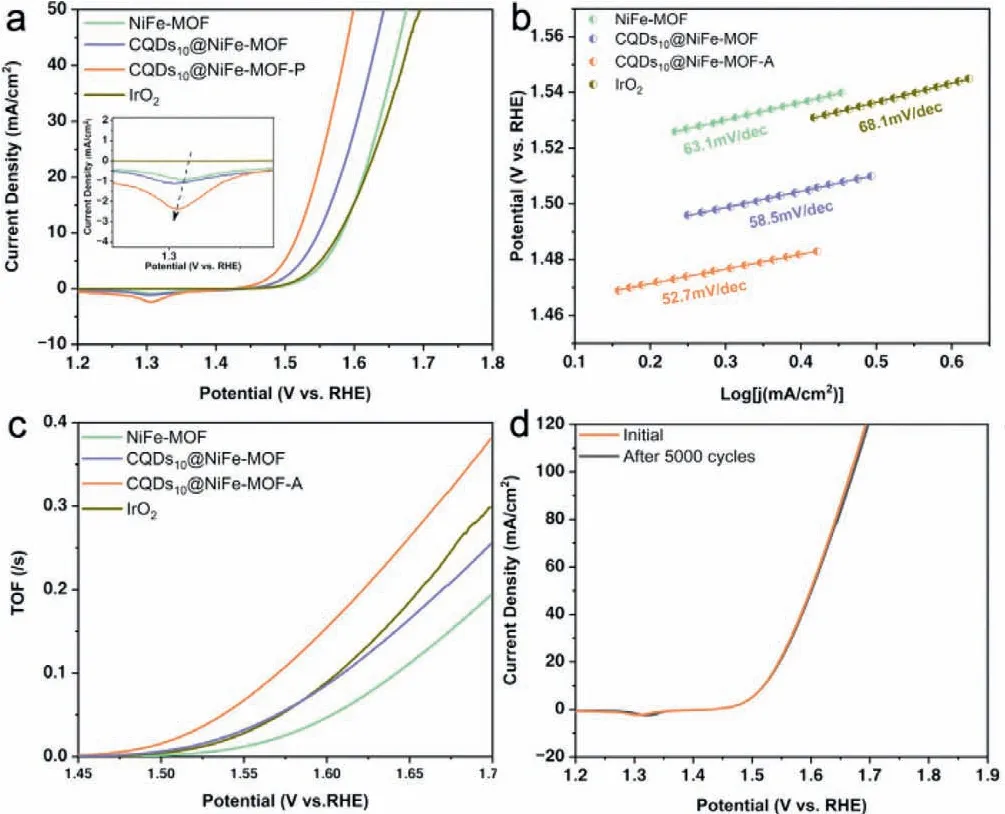
Fig.3.OER performances.(a)LSV OER polarization curves of the catalysts without iR-correction,inset:enlarged curves at around 1.3 V(vs. RHE).(b)Corresponding Tafel slope and(c)TOF in(a).(d)Polarization curves of CQDs10@NiFe-MOF-A at the 1st and 5000th cycle for OER.
The electrocatalytic activities of NiFe-MOF,CQDs10@NiFe-MOF,CQDs10@NiFe-MOF-A,and benchmark IrO2catalysts for OER were evaluated in 1 mol/L KOH with a typical three-electrode system(Fig.3a).Each catalyst was subjected to hundreds of CVs to remove the unstable components from the electrode surface and produce active substances prior to testing,and the results were shown in Fig.S8(Supporting information).Both of the CQDs10@NiFe-MOF and CQDs10@NiFe-MOF-A exhibited an obvious evolution process,with the gradual increase of Ni2+/Ni3+redox peak intensity and cut-off current density.The difference is that the CQDs10@NiFe-MOF almost completed activation process after 20 CVs,while CQDs10@NiFe-MOF-A took almost 50 CVs,meaning more active sites for OER were generated[23].As for NiFe-MOF,this process was compressed within 10 CVs,so that the final cut-off current density was not greatly increased.Compared with the IrO2,the LSV curves withoutiR-correction of the NiFe-MOF,the CQDs10@NiFe-MOF and calcined CQDs10@NiFe-MOF-A revealed distinct redox peaks at about 1.3 V,which was caused by nickel species in the samples.Among them,the CQDs10@NiFe-MOF-A exhibited the highest intensity of Ni2+/Ni3+redox peak at 1.3 V(vs.RHE,inset in Fig.3a),suggesting more electrochemically active layers(hydroxide/oxyhydroxide)were generated[24],which is essential to boost the OER performance.The OER metal redox peak shifted negatively upon the introduction of CQDs into the NiFe-MOF and calcination,indicating the presence of a strong synergistic electronic interaction between the CQDs and Ni/Fe ions[25,26].Therefore,a much better OER performance was achieved by CQDs10@NiFe-MOF-A,which was demonstrated by the overpotentials(Fig.S9 in Supporting information)and Tafel slope in Fig.3b.In Fig.S9,only 289 mV was needed to deliver the current density of 10 mA/cm2(η10=289 mV)with ultralow loading mass of 150 μg/cm2for CQDs10@NiFe-MOF-A,and it outperformed that of NiFe-MOF(η10=352 mV)and CQDs10@NiFe-MOF(η10=319 mV).The CQDs10@NiFe-MOF-A also exhibited lower overpotentials at higher current densities,ofwhichη20=315 mV andη50=369 mV,surpassed those of NiFe-MOF(η20=383 mV,η50=445 mV),CQDs10@NiFe-MOF(η20=350 mV,η50=413 mV)and IrO2(η20=386 mV,η50=465 mV).Tafel slopes in Fig.3b showed the CQDs10@NiFe-MOF-A possessed a smaller Tafel slope(52.7 mV/dec)than NiFe-MOF(63.1 mV/dec),CQDs10@NiFe-MOF(58.5 mV/dec)and IrO2(68.1 mV/dec),which indicated doping of CQDs and calcination intrinsically accelerated its OER kinetics.The CQDs10@NiFe-MOF-A also had advantages in electrochemical surface area(ECSA),which was estimated by the double-layer capacitance(Cdl)in Fig.S10(Supporting information).TheCdlvalve of CQDs10@NiFe-MOF-A was 267.6 μF/cm2and almost 3.3 times and 1.3 times as large as that of NiFe-MOF(80.5 μF/cm2)and CQDs10@NiFe-MOF(201.7 μF/cm2),respectively,indicating abundance surface active sites were formed by introducing CQDs to NiFe-MOF and calcination,which was beneficial to mass transport during OER.To further evaluate the intrinsical activity of these catalysts,turnover frequency(TOF)was compared,which represented the reaction rate of per active site in unit time.Fig.3c revealed that CQDs10@NiFe-MOF-A exhibited the highest TOF valve at the range of 1.45–1.7 V(vs.RHE)among the four samples,demonstrating its intrinsically enhanced OER performance.Moreover,the current density was mass-normalized at the overpotential=300 mV.As shown in Fig.S11(Supporting information),CQDs10@NiFe-MOFA possessed a mass-normalized current density of 91.6 A/g,which was 3.6 times that of IrO2.These results depicted the significant improvement of intrinsic activity by the incorporation of CQDs and the low temperature calcination.Thus,the CQDs10@NiFe-MOF-A is comparable even surpasses most of state-of-the-art MOF-based catalysts at the same load(Fig.S12 and Table S1 in Supporting information).
Mechanical robustness and long-time durability showed the equal importance to the practical applications of the catalysts.The LSV curves of CQDs10@NiFe-MOF-A after continuous and repeated CV measurements at the scanning rate of 500 mV/s from 1.42 V to 1.77 V(vs.RHE)were recorded.Fig.3d showed the curve after 5000 cycles overlapped with the initial one,illustrating the outstanding stability of the CQDs10@NiFe-MOF-A.Another 5000-cycle measurement was taken and the LSV curve kept consistent with the initial one in the low current density region while showed a slight positive shift in the large potential region(Fig.S13 in Supporting information).We speculated the attractive stability is endowed by the low-temperature calcination,which was supported by the significantly declined LSV curve of the CQDs10@NiFe-MOF in Fig.S14(Supporting information).Long-term chronoamperometry test was performed by exerting a settled voltage of 1.525 V(vs.RHE)continuously for 30,000 s in 1 mol/L KOH.During the first 5000 s,the current density ascended slightly from 10.4 mA/cm2to 11 mA/cm2(Fig.S15 in Supporting information),which was caused by the surface activation,then the current density remained 90.5%of initial after 30,000 s.The structure of CQDs10@NiFe-MOF-A after long-time stability test showed unchanged sturcture of nanoparticle clusters,indicating its good mechanical robustness and structural stability(Fig.S16 in Supporting information).Overall,the CQDs10@NiFe-MOF-A showed sufficient stability to be adequate for extended applications.
To further investigate the evolution of oxygen performance of CQDs10@NiFe-MOF-A,more electrochemical characterization was performed.Electrochemical impedance spectroscopy(EIS)is a potentially practical approaches to explore the kinetics of electrocatalytic reactions and the evolution of the electrode/electrolyte interface[15],and the semicircle of the samples decreased significantly as the introduction of CQDs and calcination(Fig.S17 in Supporting information).Operando electrochemical impedance spectroscopy of CQDs10@NiFe-MOF-A was conducted at the potential range from 1.47 V to 1.57 V(vs.RHE),and the NiFe-MOF was chosen as the control sample to investigate the effect of the CQDs incorporation on electrical conductivity.Nyquist plots measured for them at different potentials were displayed in Figs.4a and b,and an equivalent circuit was used to fitted these plots,which was shown in Fig.S18(Supporting information),and corresponding fitting parameters have been listed in Tables S2 and S3(Supporting information).The adsorption behavior of intermediates∗OH can be traced by differentRctand CPEct[27],which represents charge transfer resistance and constant phase element,respectively.The variation of total charge transfer resistance(Rtotal)was predominated byRctsince the two samples exhibited the same solution resistance(Rs).The lowerRtotalat each potential demonstrated a more facile reaction for∗OH adsorption was occurred to CQDs10@NiFe-MOF-A(Fig.4c),which meant successful incorporation of CQDs and significant enhancement of electrical conductivity,therefore,the more electrons were involved into the OER process.The Bode phase plot of NiFe-MOF and CQDs10@NiFe-MOF-A at the potential of 1.52 V(vs.RHE)was shown in Fig.4d.According to the previous reports[28],the lower phase angle and shift in the low-frequency region is related to the faster deprotonation of∗OOH intermediates.Hence,the CQDs10@NiFe-MOF-A could behave a much more attractive OER performance.

Fig.4.EIS performances of NiFe-MOF and CQDs10@NiFe-MOF-A.Nyquist plots of(a)CQDs10@NiFe-MOF-A and(b)NiFe-MOF at different applied potentials(vs. RHE).(c)Total charge transfer resistance(Rtotal)at the different applied potentials.(d)Bode phase plots at 1.52 V(vs. RHE).
Finally,the effect of CQDs dosage loaded on MOF toward OER performance was evaluated.Different contents of CQDs(0 mg,5 mg,7 mg,15 mg,20 mg)were incorporated into the MOF matrix and followed by calcination treatment with the same method as that used in CQDs10@NiFe-MOF-A synthesis.SEM images in Fig.S19(Supporting information)showed their almost undifferentiated morphology,suggesting that the amount of carbon dots did not affect the appearance of the consequent catalyst.However,the extra CQDs did not lead to an additional increase in OER activity,which may be caused by the obstructed pore structure and active sites.As shown in Figs.S20a and b(Supporting information),the LSV of CQDs10@NiFe-MOF-A overwhelmed other curves,demonstrating the significance of the proportion of CQDs and MOF.The obtained Tafel slope depicted the intrinsically accelerated kinetics.EIS measurements and XRD was adopted to explain these results.In Figs.S20c and d(Supporting information),EIS and XRD results of the catalysts were displayed.Notably,there was a “volcano type” relationship among those diameters of Nyquist plots.We speculate that when the ratio of MOF and CQDs were in a certain range,more CQDs can effectively promote charge transfer,involving more electrons in the OER reaction.While too much introduced CQDs would further disrupt the lattice of the MOF matrix,and thus,the amorphization was expanded(Fig.S20d),which was not conducive to the reaction.After all,it is the synergistic effect between CQDs and defective MOFs that really plays a role during the catalytic reaction.
In summary,a composite porous MOF doped with carbon quantum dots CQDs10@NiFe-MOF-A was synthesized as a desired and stable catalyst for OER.Inherent high catalytic activity endowed by NiFe-MOF,as well as the largely enhanced conductivity by the appropriate introduction of CQDs made the CQDs10@NiFe-MOF-A an ideal non-noble metal catalyst,which only required an overpotential of 289 mV to deliver a current density of 10 mA/cm2,lower than that of IrO2of 349 mV.Fortunately,the way of introducing CQDs is feasible and successful,and it has been verified by the Nyquist plots and Bode phase plots,where the charge transfer resistance was significantly decreased.Furthermore,low-temperature calcination not only reduced crystallinity of the samples,but also stabilized the structure of the hybrid MOF,resulting in a better stability of CQDs10@NiFe-MOF-A,which can withstand a 10,000-cycle-CV testing with negligible activity decline.Hence,the strategy can be expanded for other material systems to improve poor electrical conductivity and enhance catalytic performance.
Declaration of competing interest
The authors declare no conflict of interest.
Acknowledgments
This work was financially supported by the Fundamental Research Funds for the Central Universities(No.2042021kf0077),Start-up funds for provincial and municipal "double first-class"construction special talents(No.600460001)as well as China postdoctoral Science Foundation(No.2017M612496).
Supplementary materials
Supplementary material associated with this article can be found,in the online version,at doi:10.1016/j.cclet.2021.08.028.
 Chinese Chemical Letters2022年1期
- Chinese Chemical Letters的其它文章
- Engineering carbon nanocatalysts towards efficient degradation of emerging organic contaminants via persulfate activation:A review
- Recent advances in nanoscale metal-organic frameworks biosensors for detection of biomarkers
- Porphyrin-based heterogeneous photocatalysts for solar energy conversion
- Systematic evaluation of advance in application and discharge mechanism of solution electrode glow discharge
- Insoluble carbonaceous materials as electron shuttles enhance the anaerobic/anoxic bioremediation of redox pollutants:Recent advances
- Selective N-terminal modification of peptides and proteins:Recent progresses and applications