Introduction of a New Method for Regulating Laves Phases in Inconel 718 Superalloy during a Laser-Repairing Process
Shang Sui, Haosheng Li, Zuo Li, Xuan Zhao, Liang Ma, Jing Chen,*
aState Key Laboratory of Solidification Processing, Northwestern Polytechnical University, Xi’an 710072, China
b Key Laboratory of Metal High Performance Additive Manufacturing and Innovative Design,Ministry of Industry and Information Technology,Northwestern Polytechnical University,Xi’an 710072, China
Keywords:Laser repair In situ laser heat treatment Inconel 718 alloy Laves phase
A B S T R A C T The morphology, size, and distribution of Laves phases have important influences on the mechanical properties of laser-repaired Inconel 718 (IN718) superalloy. Due to the deterioration of the substrate zone, the Laves phase in the laser cladding zone of IN718 superalloy cannot be optimized by a hightemperature solution treatment. In this study, an in situ laser heat-treatment method was proposed to regulate the morphology and size of the Laves phase in the laser cladding zone of IN718 superalloy without impacting the substrate zone.In the in situ laser heat-treatment process,a laser was used to heat previously deposited layers with optimized manufacturing parameters. A thermocouple and an infrared camera were used to analyze thermal cycles and real-time temperature fields, respectively.Microstructures and micro-segregations were observed by optical microscopy, scanning electron microscopy, and electron probe microanalysis. It was found that the in situ laser heat treatment effectively changed the morphology and size of the Laves phase, which was transformed from a continuous striplike shape to a discrete granular shape. The effective temperature range and duration were the two main factors influencing the Laves phase during the in situ laser heat-treatment process. The effective temperature range was determined by the laser linear energy density, and the peak temperature increased with the increase of the linear energy density. In addition, the temperature amplitude could be reduced by simultaneously increasing the laser power and the scanning velocity. Finally, a flow diagram was developed based on the in situ laser heat-treatment process, and the deposition of a single-walled sample with fine and granular Laves phases was detected.
1. Introduction
Inconel 718 (IN718), as one of the most widely used nickelbased superalloys in aviation, aerospace, energy, and chemical industries, is generally used for manufacturing integral structural components due to its excellent mechanical properties below 650 °C [1–3]. However, when these integral structures are damaged due to mismachining or external forces during service periods, great losses of money and time occur [4]. Laser repair technologies based on laser-directed energy deposition have several advantages of low heat input,low distortion,and low residual stress; thus, they can be utilized to recover the geometric and mechanical performances of damaged integral components.
The microstructure of laser-repaired IN718 superalloy can be divided into laser cladding and substrate zones[4].Severe Nb segregation occurs in the inter-dendritic region of the laser cladding zone during a laser repairing process[5];hence,numerous continuous and irregular Laves phases precipitate at the end of solidification due to a eutectic reaction (Liquid →γ + Laves). However, no Laves phase is formed in the substrate zone when microstructures are forged [6]. As hard and brittle micro-scale precipitates, Laves phases hinder the motion of dislocations,leading to stress concentration.Consequently,cracks begin to form at the γ–Laves interface and deteriorate the mechanical properties of the laser cladding zone, causing the fracture of this region under tensile [6] and high-temperature stress rupture loads [7].
The morphology, size, and distribution of Laves phases have important influences on the mechanical properties of laser-repaired IN718 superalloy [8]. Unlike continuous and strip-shaped Laves phases, discrete and granular Laves phases obtained by short-term solution treatments can promote coordinate deformation, reduce stress concentration, and improve mechanical properties.Therefore,the optimization of Laves phases is important for laser-repaired IN718 superalloy.
The regulation of Laves phases can be performed by two methods. First, the suppression of Nb segregation to some extent by controlling solidification conditions (temperature gradient and solidification rate) can hinder the growth of Laves phases [9–12].A low-temperature gradient ratio, a low solidification rate, and a high cooling rate can reduce the degree of Nb segregation and refine Laves phases by reducing their volume fraction and size[11]. However, solidification conditions differ between various regions of a molten pool and vary as the height of the laserrepaired area increases, due to heat accumulation; therefore, it is difficult to obtain stable solidification conditions. Second, homogenization heat treatments are proved to be effective for regulating Laves phases[8,13–16].High-temperature solution treatments can effectively eliminate elemental segregation and regulate the morphology and size of Laves phases [14]. In cast IN718 superalloy,the dissolution of large Laves phase particles (dozens of microns)into the matrix is very difficult [17–19]. Miao et al. [19] reported that a long duration of greater than 20 h was required to completely dissolve the Laves phase when the heat-treatment temperature was 1140 °C. It is proved that interactions between alloying elements can decrease the diffusion rate of Nb in IN718 superalloy[17]. Pan et al. [18] designed a three-step heat-treatment process with temperatures greater than 1100 °C to eliminate Nb segregation and Laves phases.In our recent investigation[13],it was found that the dissolution rate of the Laves phase in IN718 alloy fabricated by laser-directed energy deposition was higher than that of cast IN718 superalloy. However, a temperature of greater than 1050 °C and a duration of longer than 45 min were still necessary for the complete removal of the Laves phase.The above-mentioned post-heat-treatment processes inevitably degrade the mechanical properties of the substrate zone; therefore, homogenization heattreatment processes are required [2].
In the present study,an in situ laser heat-treatment method was proposed to effectively regulate the Laves phase without affecting the microstructure of the substrate zone during a laser-repairing process. The influences of the in situ laser heat treatment on the microstructural evolution of laser cladding and substrate zones were investigated. Furthermore, a thermocouple and an infrared camera were used to explore the real-time temperature distribution during the in situ laser heat treatment, and the effects of in situ laser heat-treatment parameters on the temperature distribution were also revealed. Finally, a sample with a fine and discrete Laves phase was produced by the proposed method.
2. Experimental details
Spherical IN718 powder with a particle size range of 15–53 μm prepared by the plasma rotating electrode process was used in the laser repairing experiment, and its chemical composition is presented in Table 1. The alloy powder was dried at 120 °C for 2–3 h and cooled to room temperature (25 °C) in a vacuum furnace before the experiment. A forged IN718 alloy was used as the substrate, and its chemical composition is also listed in Table 1. The alloy sample was cut into thin plates of 40 mm (length) × 2 mm(width) × 40 mm (height) size by an electrospark wire-electrode cutting machine. Plate surfaces were polished with sandpapers to remove oxide scales, washed with acetone, and dried.
A new in situ heat-treatment method was adopted to regulate the Laves phase during the deposition process. In this technique,a laser was used to re-melt deposited layers under optimized parameters (Figs. 1(a) and (b)). The laser repairing and in situ heat-treatment parameters used in this study are presented in Table 2.The in situ heat-treatment parameters were selected based on the following two criteria:
(1) The parameters should be effective to provide enough energy to heat previously deposited layers.
(2) The re-melt region must be eliminated in the next deposition process,indicating that the depth of the re-melt region should be smaller than the melt pool depth.
The microstructure of the laser-repaired specimen was determined by optical microscopy (Keyence, Japan) and scanning electron microscopy (Tescan Vega, Czech Republic). Before the analysis,the specimen surface was etched with an etchant containing 1 g of FeCl3, 2 mL of HCl, and 10 mL of C2H5OH [20,21]. The etchant was modified based on the commonly used Kalling’s reagent [22]. The Image-Pro Plus software was used to measurethe volume fractions of the Laves phase before and after in situ laser heat treatments with different parameters.Furthermore,elemental distributions were explored by electron probe microanalysis (Shimadzu, Japan).

Table 1 The nominal chemical composition of IN718 powder and substrate.

Fig. 1. The schematic diagram: (a) laser repair process; (b) in situ laser heat-treatment process; and (c) the position of points for temperature measuring.

Table 2 The parameters of laser repair and in situ laser heat-treatment experiments.
In order to investigate the effectiveness of the proposed in situ laser heat-treatment method in regulating the Laves phase, a single-walled sample with a length of 35 mm and a height of 15 mm was deposited. GG-K-30 thermocouples (Omega, USA)were welded into the sidewall at the positions shown in Fig. 1(c).The real-time temperature distribution in the sample during the in situ laser heat-treatment process was recorded by the ImageIR 8355 infrared camera (InfraTec, Germany), and the subsequent analysis was conducted by the IRBIS3 software.
3. Results and discussion
3.1. Microstructural evolution in the laser cladding zone
Fig. 2 exhibits the microstructures of the laser-repaired IN718 alloy before and after the in situ laser heat treatment. The nontreated microstructure contained columnar crystals that epitaxially grew along the deposition direction(Fig.2(a)).As the direction of the temperature gradient at the solid–liquid interface of the molten pool changed from vertical to horizontal,the growth direction of the dendritic structure at the top of the cladding layer also changed to horizontal [23]. Therefore, a dendritic region with a height of 140 μm was formed at the top of the cladding layer(Fig. 2(a)).
The grain morphology did not change significantly after the in situ laser heat treatment, and columnar crystals that grew epitaxially along the deposition direction were still predominant. A re-melting zone with a height of 480 μm was formed at the top of the cladding layer and had a significantly different microstructure to that of the non-treated alloy. A much finer dendritic structure was formed in the re-melting zone due to the relatively high cooling rate. In addition, grain boundaries (GBs) dissolved and tended to appear blurred due to the heating effect (Fig. 2(d)).
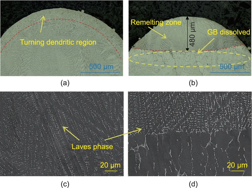
Fig.2. Microstructure of the laser-repaired IN718 superalloy without and with the in situ laser heat treatment: (a, c) without in situ laser heat treatment; (b, d) with in situ laser heat treatment. GB: grain boundary.
Figs. 3(a)–(f) display the evolution of the Laves phase 1–2 mm away from the upper sample surface after the in situ laser heat treatment.The morphology of the Laves phase changed from a continuous strip-like shape to a discrete granular one with the increase of the heat-treatment time. In addition, the boundary of the Laves phase began to become smooth, indicating the occurrence of the dissolution mechanism. The volume fractions of the Laves phase were quantitatively measured based on the Cavalieri–Hacquert rule [24,25], and the corresponding results are presented in Fig.3(g).With the prolongation of the in situ laser heat treatment, the volume fraction of the Laves phase was reduced gradually. After 180 s of the in situ laser heat treatment,the volume fraction of the Laves phase decreased by 63.10% from its original state.
3.2.Elemental segregation and dissolution behavior of the Laves phase
Fig. 4 displays the distribution of elements 1–2 mm away from the upper sample surface after the in situ laser heat treatment.The formation of the Laves phase was associated with the severe segregation of elements, especially Nb and Ti, in the inter-dendritic region. In IN718 superalloy, Nb and Ti are the main elements of strengthening precipitates. The heterogeneous distribution of Nb and Ti causes an uneven distribution of γ′and γ′′phases during subsequent aging and significantly influences the mechanical performance of IN718 superalloy [8,26–28]. During the in situ laser heat treatment, solute atoms diffused from the solute-rich region to the matrix; thus, the extent of elemental segregation was gradually relieved [29]. After 30 s of the in situ laser heat treatment,‘‘long strip” areas enriched with Nb were still present in the inter-dendritic region. When the treatment duration increased from 90 to 180 s, these ‘‘long strip” regions gradually became‘‘islands” (Figs. 4(d)–(f)). The extent of Ti segregation was slightly lower than that of Nb, and Ti-rich regions exhibited similar evolution characteristics to Nb-rich ones(Figs.4(c)–(f)).The distribution of Al during the in situ laser heat treatment was not prominent due to its low content in IN718 superalloy.
Fig. S1 (in Appendix A) presents the morphology of the Laves phase after 60 s of the in situ laser heat treatment. Sharp corners and grooves of the Laves phase dissolved preferentially, and its edges became smooth. This phenomenon could be attributed to the higher solubility of areas with a smaller curvature during the dissolution process [30]. In addition, dissolution occurred preferentially at the second phase/matrix interface to restore the concentration balance. Enomoto and Nojiri [31] also found that a small curvature reduced the dissolution time of second-phase particles.The long strip-like Laves phase moved inward from the center and further dissolved along the yellow dotted line shown in Fig. S1(b) to form two smaller discrete parts.
3.3. Microstructural evolution in the substrate zone

Fig.3. Evolution of the Laves phase after the in situ laser heat treatment:(a)0 s;(b)30 s;(c)60 s;(d)90 s;(e)120 s;(f)180 s;and(g)volume fraction of the Laves phase after the in situ laser heat treatment.
The microstructural evolution in the substrate zone after the in situ laser heat treatment is exhibited in Figs. S2 and S3 (in Appendix A). Due to the high temperature at the bottom of the molten pool, the microstructure of the substrate zone close to the repair interface changed,and this phenomenon could be characterized by the growth of equiaxed grains and the complete dissolution of original second phases in the matrix(Fig.S3(a)),forming a bright white area (Fig. S2(a)). However, fine and uniformly distributed nanoscale γ′and γ′′precipitates were still present in the substrate zone below the bright white area (Fig. S3(d)).
After in situ laser heat treatments for different durations, the width of the bright white area and the grain size in the substrate zone remained the same (Figs. S2(b)–(f)). Furthermore, the morphology, size, and distribution of strengthening phases also remained unchanged in the region below the bright white area(Figs.S3(e)and(f)).These phenomena indicate that the in situ laser heat treatment had little influence on the substrate zone; therefore, the Laves phase in the laser cladding zone could be locally regulated.
The optimization of the Laves phase without influencing the substrate zone was closely related to temperature distribution during the in situ laser heat treatment. In the following sections, we focus on the effect of two main critical parameters: energy input and duration.
3.4. Effects of energy input on temperature distribution during the in situ laser heat treatment
The melting points of the Laves phase, MC carbides, and the γ matrix were calculated as 1143, 1215, and 1337 °C, respectively,by differential scanning calorimetry (DSC) (Fig. S4 in Appendix A)[14]. Therefore, due to different melting points, the Laves phase could be regulated without influencing the γ matrix. The dissolution of the Laves phase during the in situ laser heat-treatment process was closely related to the temperature. Generally, the temperature required for regulating the Laves phase during a solution heat-treatment process is 50–150 °C lower than its melting point [32,33], and the energy input during an in situ laser heattreatment process is one of the important factors affecting the temperature field and thus influencing the dissolution of the Laves phase.
In this study, the linear laser energy density (Eq. (1)) was used to calculate the energy input during the in situ laser heat treatment:

where Elis the linear laser energy density,and P and v are the laser power and the scanning velocity, respectively.
The linear energy densities corresponding to different in situ laser heat-treatment parameters are presented in Table 2. Fig. S5(in Appendix A)displays the thermal cycle curves at different temperature measurement points under different process parameters.It is noticeable that all temperature curves first increased and then became stable as the treatment duration increased. Although the temperature data at point 3 were not successfully obtained due to a connection problem,a clear relationship could still be inferred from the other four points.The peak temperatures of the temperature measurement points increased gradually with the increase of the linear energy density(Fig.5(a)).Furthermore,the temperatures of points 1 and 2 met the temperature requirements for the dissolution of the Laves phase under all process parameters. In addition,the temperature decreased gradually as the distance from the upper surface of the sample increased.Therefore,the temperatures at points 4 and 5 decreased and could not induce the dissolution of the Laves phase.
Now, taking point 1 as an example, Fig. 5(b) presents the relationship between the time required for the temperature to be stabilized and the linear energy density. The time required for the temperature to stabilize decreased as the linear energy density increased,indicating that the temperature field of the sample could be stabilized quicker when a higher linear laser energy density was used.It happened because at a high linear energy density,the heat input was high and the increase rate of temperature was also high.
The thermal behavior of the sample was cyclic and nonuniform. In order to ensure that the dissolution process of the Laves phase reaches a stable state as soon as possible,the thermal cycle of the sample should be in a relatively constant state. The thermal cycling curve T could be described by a sinusoidal function:

where A=ΔT/2(ΔT is the difference between the highest temperature and lowest temperature in an amplitude), which is related to the linear energy input; angular frequency w = 2πv/L, which is related to the length of the scanning area (L) and the scanning velocity (v); t is the time; φ is the initial phase, which represents the phase at t = 0; and Tcis the average temperature during the in situ laser heat treatment.
With the decreasing scanning length and the increasing scanning velocity, the sample would absorb more energy and the amplitude could be easily maintained in a small range.In this scenario, the temperature of each position on the sample would be relatively constant; however, it is impossible to reach this ideal state.
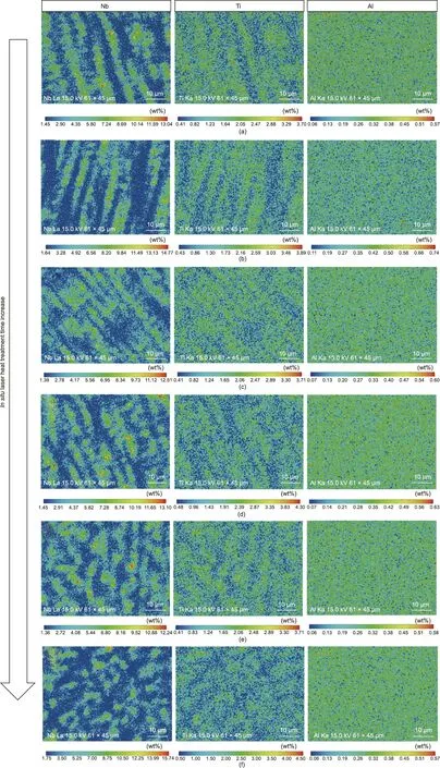
Fig. 4. Element distribution after the in situ laser heat treatment: (a) 0 s; (b) 30 s; (c) 60 s; (d), 90 s; (e) 120 s; and (f) 180 s.
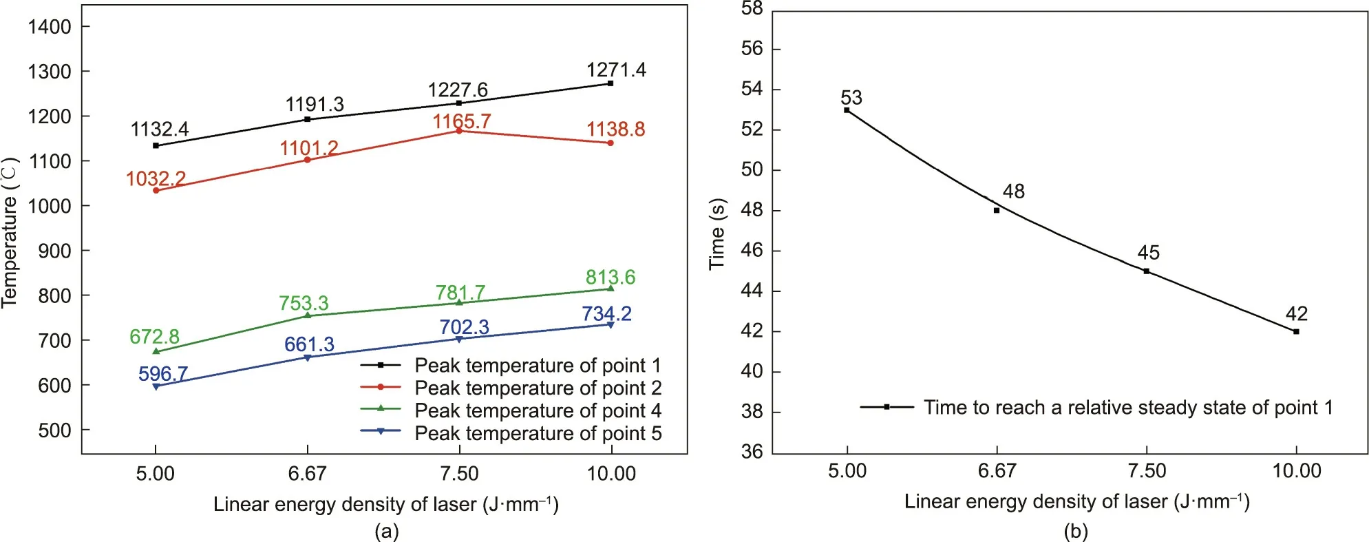
Fig. 5. (a) Peak temperature of the measurement points under different liner energy densities; (b) time required for the temperature to reach a steady state of point 1.
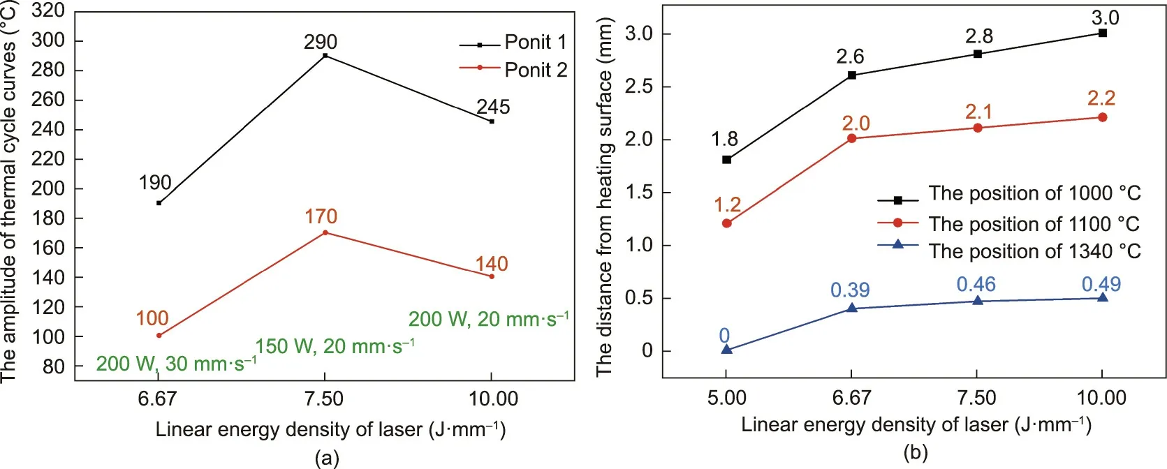
Fig. 6. (a) The amplitude of thermal cycle curves under different process parameters; (b) position of different temperatures under different liner energy densities.
Fig. S6 (in Appendix A) present the thermal cycle curves of the temperature measurement points in a relatively steady state under different parameters.The temperature amplitudes of the measurement points decreased as the distance from the upper sample surface increased. Furthermore, the temperatures at points 4 and 5 only fluctuated within a maximum range of 50°C.The temperature amplitudes at points 1 and 2 varied with process parameters(Fig. 6(a)). No clear correlation between temperature amplitudes and the linear energy density was noticed; however, temperature amplitudes were closely related to the laser power and the scanning velocity.When the scanning velocity was fixed at 20 mm∙s-1,the temperature amplitude at point 1 decreased from 290 to 245°C as the laser power increased from 150 to 200 W. When the laser power was fixed at 200 W,the temperature amplitude was further reduced from 245 to 190°C as the scanning velocity increased from 20 to 30 mm∙s-1. The temperature amplitude at point 2 exhibited the same trend. Therefore, an effective method for reducing the temperature amplitude is the simultaneous increase in the laser power and the scanning velocity. In addition, when the size of the scanning area was fixed,the angular frequencies of the thermal cycle curves were determined by the scanning velocity, and the higher the scanning velocity, the higher the angular frequency.
The thermocouple temperature measurement only revealed thermal cycles at certain points, therefore, this method had some limitations in reflecting the temperature distribution in the whole sample. Therefore, an infrared camera was used to elucidate the real-time temperature distribution in the sample during the in situ heat treatment.Fig.S7(in Appendix A)displays the temperature field of the sample after ten thermal cycles under different in situ laser heat-treatment parameters. The temperature field was first captured by the infrared camera and then calibrated by comparing temperatures of the two methods at the same position in the high-temperature zone. The temperature of the sample gradually increased as the linear energy density increased.
In order to determine the depth of the re-melting zone and the size of the area in which the Laves phase could effectively dissolve,the distances between the temperatures of 1000 °C (temperature at which the Laves phase dissolved),1100°C,and 1340°C(melting point of IN718 superalloy) and the sample surface were obtained by the infrared camera results (Fig. 6(b)). In this experiment, for a cyclic heating process, the temperature corresponds to the peak temperature. Therefore, it was possible to determine the position of the re-melting layer based on the position of the temperature of 1340 °C. The blue line in Fig. 6(b) indicates that the depth of the laser re-melting zone for the laser power of 200 W and the scanning velocity of 20 mm∙s-1was 0.49 mm.
The black line in Fig.6(b)indicates the dissolution region of the Laves phase. Based on the data obtained from the black and blue lines, the height of the cladding zone could be determined. For example, when the applied laser power was 200 W and the scanning velocity was 20 mm∙s-1, the temperature gradient was estimated to be approximately 135 °C per millimeter. In order to minimize the influences of the in situ laser heat treatment on the substrate zone, the temperature of the repair interface should be below 620 °C (precipitation temperature of the γ′phase). The height of the cladding zone after the first laser heat treatment was calculated as approximately 5.8 mm.
3.5. Effects of heat-treatment duration on temperature distribution
Fig. S8 (in Appendix A) exhibits the real-time temperature distribution in the sample after in situ heat treatments for 15–60 s with a laser power of 200 W and a scanning velocity of 20 mm∙s-1.The temperature of the whole sample first gradually increased(Figs. S8(a) and (b)) and became stabilized (Figs. S8(c) and (d)) as the treatment duration increased. As the dissolution of the Laves phase was dominated by the diffusion of Nb, the extension of the in situ laser heat-treatment duration had a great effect on the temperature distribution when the temperature was relatively stable.
The above analysis indicates that the proposed in situ laser heattreatment method could effectively regulate the morphology and size of the Laves phase in the laser cladding zone during the laser repairing process.The temperature range for the dissolution of the Laves phase increased as the laser linear energy density increased.In addition,a relatively constant sample temperature was achieved by increasing the laser power and the scanning velocity.Moreover,the prolongation of the in situ laser heat-treatment duration also contributed to regulating the Laves phase.
4. In situ laser heat-treatment process
In the current section, a flow diagram is depicted to optimize the Laves phase in real-time during a laser repairing process based on the proposed method.
The flowchart is displayed in Fig. 7(a), and its specific steps are described below.
(1) Preparation: This step includes the preparation of the powder, the substrate, and other components. The powder must be pre-dried, and the surface of the substrate should be polished and wiped with acetone.
(2) Pre-experiment: Based on the dimensions of the required sample, temperature measurement devices, such as infrared cameras and thermocouples, should be used to obtain the real-time temperature field and select appropriate in situ laser heattreatment parameters. The temperature must be sufficiently high to allow the Laves phase to dissolve and reach a stable state as quickly as possible.
(3) Laser deposition: Laser deposition must be conducted in a processing platform under atmospheric conditions or a processing chamber under an inert atmosphere.An IN718 superalloy containing continuous strip-shaped Laves phases with a certain height is prepared. The height is correlated to the depth of the effect of the selected in situ laser heat-treatment parameters on the deposited layers.
(4) In situ laser heat treatment: The sample should be scanned with selected parameters for a certain time to regulate the morphology and size of the Laves phase.
(5) Judgment:Whether the dimension of the sample meets the expected requirements after the in situ laser heat treatment should be assessed. If all requirements are not fulfilled, steps (3) and (4)must be repeated.
(6)Output:The final sample can be then removed from the system after air-cooling to below 100°C.An IN718 superalloy sample containing discrete and granular Laves phase is finally obtained.
Based on the above flowchart, a single-walled sample with a length of 25 mm and a height of 8 mm was deposited using the following in situ heat-treatment parameters: Laser power is 200 W,scanning velocity is 20 mm∙s-1, and scanning time is 180 s. The value of N was equal to 3. The macro- and microstructures of the obtained sample are displayed in Figs. 7(b)–(e). It is observable from Fig. 7(b) that the single-walled sample contained epitaxial columnar grains. Figs. 7(c)–(e) present the morphology and size of the Laves phases at different positions of the sample. Almost all Laves phases in the sample were found to be granular, thus verifying the feasibility of the proposed in situ laser heat treatment in laser repairing processes.
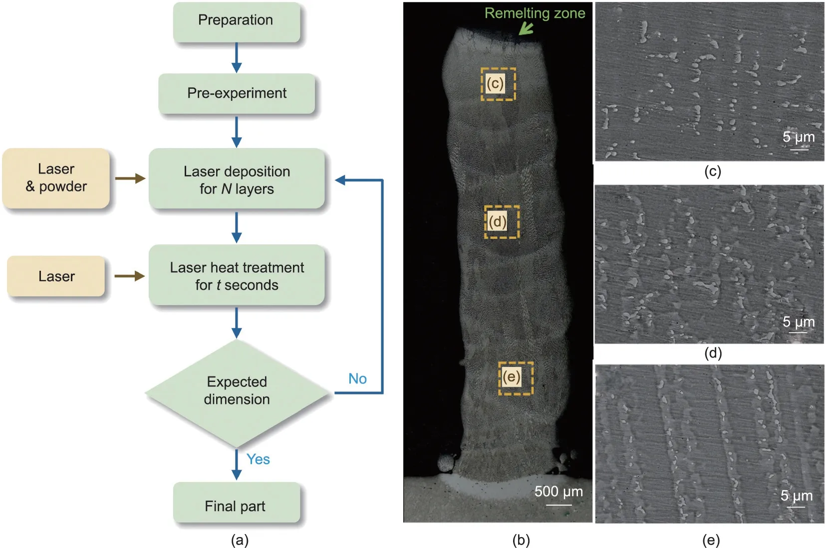
Fig. 7. (a) Flow chart of the in situ laser heat heat-treatment process; (b) macrostructure and (c–e) microstructure of the single wall sample after the in situ laser heat treatment.
5. Conclusions
An in situ laser heat-treatment method was proposed to regulate the morphology and size of the Laves phase in the laser cladding zone without affecting the microstructure and mechanical properties of the substrate. The main observations of this experiment are presented below.
(1)The in situ laser heat-treatment process effectively regulated the Laves phase.The morphology of the Laves phase changed from a continuous strip-like shape to a discrete granular one. The volume fraction of the Laves phase decreased significantly with the prolongation of the in situ laser heat-treatment time. After an in situ laser heat treatment for 180 s, the volume fraction of the Laves phase decreased by 63.1% from its original state.
(2)The temperature field of the in situ laser heat-treated sample was determined by the laser energy input and the laser scanning duration. The temperature of the sample increased as the linear energy input increased and reached a relatively stable state more quickly at higher linear energy input values.Under the same linear energy input, the temperature of the sample gradually increased and became stabilized with the prolongation of the in situ laser heat-treatment duration.
(3) When a sinusoidal function was used to describe the thermal cycle curve during the in situ laser heat-treatment process,the stability of the temperature field was determined by the amplitude and angular frequency of the thermal cycle curve.The amplitude decreased with the increase of the laser power and the laser scanning velocity.The angular frequency was related to the length of the scanning area and the scanning velocity. The shorter the length and the higher the scanning velocity,the higher the angular frequency.
(4)A flow diagram was developed based on the proposed in situ laser heat-treatment method to allow a real-time regulation of the Laves phase during the laser repairing process. According to this flow diagram,a single-walled sample with fine and granular Laves phases was obtained.
Acknowledgment
This work was supported by Aero Engine Corporation of China Xi’an Aero-Engine Ltd. (N2018KD040252), the fund of the State Key Laboratory of Solidification Processing in Northwestern Polytechnical University (2020-TS-03). We thank LetPub (www.letpub.com) for its linguistic assistance during the preparation of this manuscript.
Compliance with ethics guidelines
Shang Sui, Haosheng Li, Zuo Li, Xuan Zhao, Liang Ma, and Jing Chen declare that they have no conflict of interest or financial conflicts to disclose.
Appendix A. Supplementary data
Supplementary data to this article can be found online at https://doi.org/10.1016/j.eng.2021.08.030.
- Engineering的其它文章
- Innovative Scanners Boost Medical Imaging Quality and Utility
- Building a Highly Stable Ultrathin Nanoporous Layer Assisted by Glucose for Desalination
- Mesoscopic Modeling Approach and Application for Steel Fiber Reinforced Concrete under Dynamic Loading: A Review
- Genetic and Functional Differences of Escherichia coli Strains from Colorectal Cancer Mucosal Tissues
- Effects of Medicines and Supplements on Spontaneous Pregnancy and Semen Parameters in Male Infertility: A Systematic Review Update and Network Meta-Analysis
- Applications of CyTOF in Brain Immune Component Studies

