Theoretical investigation of ferromagnetic resonance in a ferromagnetic thin film with external stress anisotropy
Jieyu Zhou(周婕妤) Jianhong Rong(荣建红) Huan Wang(王焕) Guohong Yun(云国宏)Yanan Wang(王娅男) and Shufei Zhang(张舒飞)
1Inner Mongolia Key Laboratory of Nanoscience and Nanotechnology and School of Physical Science and Technology,
Inner Mongolia University,Hohhot 010021,China
2College of Science,Inner Mongolia Agricultural University,Hohhot 010018,China
3College of Physics and Electronic Information,Inner Mongolia Normal University,Hohhot 010022,China
Keywords: ferromagnetic resonance,external stress anisotropy,fourfold anisotropy,uniaxial anisotropy
1. Introduction
Recently,several methods have been used to research the single, bilayers and multilayers of ferromagnetic film, such as ferromagnetic resonance (FMR)[1-5]and Brillouin light scattering.[6-8]Ferromagnetic resonance is a powerful tool for quantitative determination of the properties of magnetic materials,such as magnetic anisotropies and relaxation,[9,10]magnetic coupling,[11,12]linewidth,[13-16]and others. However,in these studies,most of the investigations only take into account interlayer coupling and exchange bias.[17-23]Reports on the theoretical analysis of stress anisotropy in ferromagnetic thin film are scarcer. In fact, the controllable stress plays an important role in the FMR, which can change the properties of magnetic materials.[24]To date, although there are a few reports on stress,[25-29]the effects of the intensity and direction of external stress anisotropy on FMR are not yet thoroughly understood in a ferromagnetic thin film that includes fourfold anisotropy and uniaxial anisotropy. The motivation of the present work is to theoretically investigate the ferromagnetic resonance properties of ferromagnetic thin film with an external stress anisotropy field in detail. Therefore,in this paper, we report tuning of the FMR frequency, the linewidth and the imaginary part of magnetic susceptibility by alternating the intensity and direction of the external stress anisotropy.Also,the effect of the direction of in-plane uniaxial anisotropy is discussed in this system. Our objective is to further understand magnetic dynamic properties and show how to obtain high and controllable FMR frequency.
2. Theoretical model and calculation procedure
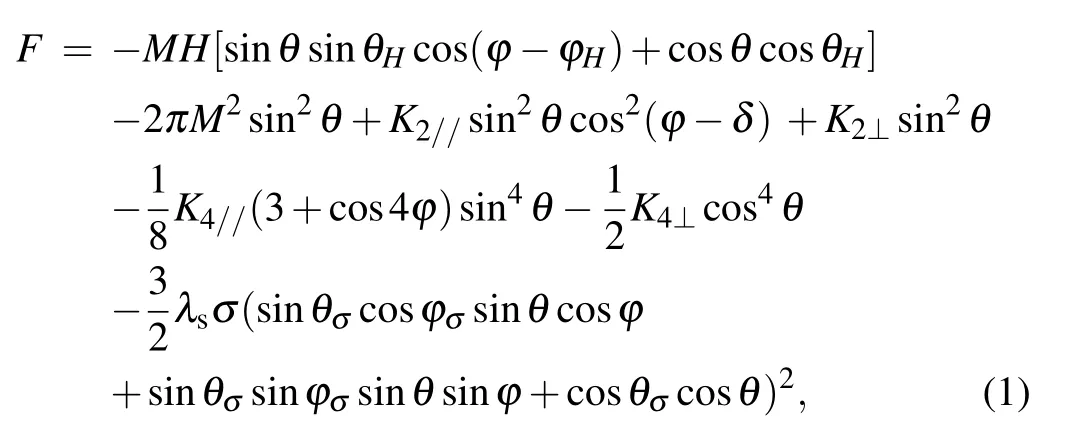
For the quantitative analysis,we have employed a model that takes into account fourfold anisotropy,uniaxial anisotropy and external stress anisotropy. The film plane lies in thex-yplane,while thezaxis is normal to it,as shown in Fig.1. The polar and azimuthal angles of the applied magnetic fieldHin the corresponding spherical coordinate system areθHandφH.Similarly,the magnetizationMand external stress anisotropy fieldHσareθandφ,θσandφσ,respectively. Here,δis the angle between the in-plane uniaxial anisotropy and thexaxis positive direction. In this model, the free energy consists of the following five terms: the Zeeman energy,the demagnetizing energy, the in-plane and out-of-plane uniaxial anisotropy energy (with constantsK2//andK2⊥), the fourfold in-plane and out-of-plane anisotropy energy (with constantsK4//andK4⊥) and external stress anisotropy energy, so the total free energy per unit area has the following form:

whereλsandσare the magnetostriction coefficient and stress intensity; for simplicity, we assume the magnetostriction of the film is isotropic.

Fig. 1. Sketch of the spherical coordinate system used to describe the orientations of applied field H,magnetization M and external stress anisotropy field Hσ in the ferromagnetic resonance analysis.
The equilibrium position of magnetization is provided by∂F/∂θ=0 and∂F/∂φ=0. It is observed that the magnetization lying in the plane,θ=θH=θσ=π/2,is a solution of the equilibrium equation. Thus, the azimuthal angle of magnetization can be determined by the following equation:

The linewidth of FMR contains some significant information for the ferromagnetic resonance modes,so the frequency linewidth Δωand field linewidth ΔHare shown as follows by using the general formula:[17,31]

2.1. Results and discussion
For comparison with Ref. [33], the corresponding numerical calculation parameters are chosen as follows:H2n=-0.14 kOe,H2w= 3.3 kOe,H4n= 0.6 kOe,M= 1.7 kG,γ/2π= 2.92 GHz/kOe,α= 0.02. Here, the in-plane uniaxial anisotropy field is along thexaxis negative direction.The FMR frequency,frequency linewidth,field linewidth and imaginary part of magnetic susceptibility as a function of the applied magnetic field for different intensities of the external stress anisotropy field are shown in Fig.2. For simplicity,the directions of the external stress anisotropy field and applied magnetic field are set in a fixed direction(φσ=φH=0°). It can be seen that the FMR frequency,frequency linewidth and field linewidth are shifted to a higher value when the intensity of the external stress anisotropy field increases [Figs. 2(a)-2(c)]. Moreover,it is observed that there is a critical fieldH′.According to the energy minimization procedure,∂2F/∂θ2>0 and∂2F/∂φ2>0,we obtainH′=-H2n+H4n+(3/2)Hσ,which is very sensitive to the in-plane uniaxial anisotropy field, fourfold in-plane anisotropy field and external stress anisotropy field. WhenH
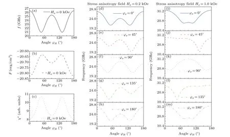
To compare with the no-external stress anisotropy field,the left panel of Fig.3 only illustrates how the direction of the applied magnetic field affects the FMR frequencyf[Fig.3(a)],magnetic free-energy densityF[Fig.3(b)]and imaginary part of magnetic susceptibilityχ′′[Fig.3(c)].Here,the intensity of the applied magnetic field is fixed at 3.0 kOe,and the effective magnetization is 18.2 kG in the numerical calculation.[33]The other parameters are the same as in Fig.2. It is found that the curves are symmetric with respect to the〈010〉direction.

Fig.2. Applied magnetic field dependence of(a)FMR frequency,(b)frequency linewidth,(c)field linewidth,and(d)imaginary part of magnetic susceptibility for different intensities of external stress anisotropy field.
The middle panel and right panel of Fig. 3 show the angular dependence of the FMR frequency with different directions of the external stress anisotropy field. The intensity of the external stress anisotropy field is fixed atHσ=0.2 kOe(middle panel) andHσ=1.0 kOe (right panel), respectively.As seen in Figs. 3(d), (f), and 3(h), the curves are symmetric about theφH=90°forφσ=0°,90°,180°. Moreover,two valleys are observed.This indicates that it is hard to magnetize along these two directions. Furthermore, the FMR frequency curves are the same when the external stress anisotropy field is parallel(φσ=0°)or antiparallel(φσ=180°)to the positive direction of thexaxis. However,forφσ=45°andφσ=135°[Figs. 3(e) and 3(g)], the symmetry is obviously broken. It clearly indicates that the direction of hard magnetization is changed.
To further reveal the effect of the external stress anisotropy field with regard to FMR frequency, the intensity of the external stress anisotropy field is increased up to 1.0 kOe. As shown in the right panel of Fig.3,the FMR frequencies of the system are maximal and the same atφH=0°andφH=180°, except forφσ=90°. This shows that it is easy to magnetize along these two directions. When we compare the middle panel with the right panel,as we increase the intensity of the external stress anisotropy field,the double valleys are not significant for the directions of the external stress anisotropy field along〈100〉,〈010〉and〈¯100〉. Outside of these directions,atφσ=45°andφσ=135°,only one valley can be found in the full range of the angleφHin the in-plane configuration. For theφσ=90°direction, the easy magnetization direction is alongφH=90°. These results demonstrate that the hard and the easy magnetization directions can be controlled by tuning the external stress anisotropy field.

Fig.3. Direction of the applied magnetic field dependence of FMR frequency,magnetic free-energy density and imaginary part of magnetic susceptibility in the absence of external stress anisotropy field(left panel). FMR frequency dependent on the direction of applied magnetic field with different directions of external stress anisotropy field: Hσ =0.2 kOe(middle panel)and Hσ =1.0 kOe(right panel).

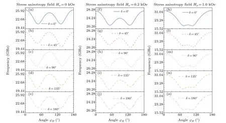
Fig.4. FMR frequency as a function of the direction of applied magnetic field for different directions of in-plane uniaxial anisotropy field: Hσ =0 kOe(left panel),Hσ =0.2 kOe(middle panel),and Hσ =1.0 kOe(right panel).
Next, to further investigate the effect of the direction of the in-plane uniaxial anisotropy field on the properties of thin film, we plot the FMR frequency (Fig. 4) and imaginary part of magnetic susceptibility(Fig.5)as a function of the direction of the applied magnetic field for different in-plane uniaxial anisotropy field directions. Here,the intensity of the external stress anisotropy field is fixed at 0 kOe,0.2 kOe,1.0 kOe,respectively,corresponding to its direction applied along thexaxis positive direction (φσ=0°). The comparison between Figs. 4 and 5 shows that the difference between two applied magnetic field directions corresponding to the minimum (maximum) value of the FMR frequency (imaginary part of magnetic susceptibility)is decreased with the increasing intensity of the external stress anisotropy field. In addition, both the direction of the in-plane uniaxial anisotropy field and the intensity of the external stress anisotropy field can destroy the symmetry,and change the hard and easy magnetization directions drastically. Specifically, as the intensity of the external stress anisotropy field increases, the maximum of the FMR frequency and imaginary part of magnetic susceptibility are shifted toward the higher value.

Fig.5. Angle dependence of the imaginary part of magnetic susceptibility for different directions of the in-plane uniaxial anisotropy field: Hσ =0 kOe(left panel),Hσ =0.2 kOe(middle panel),and Hσ =1.0 kOe(right panel).
3. Conclusion
In summary, the effect of the intensity of the external stress anisotropy field on a ferromagnetic thin film is obtained. It is revealed that the FMR frequency and imaginary part of magnetic susceptibility are enhanced,and the frequency linewidth or field linewidth can be broadened when the intensity of the external stress anisotropy field increases.In addition, the effects of the directions of the external stress anisotropy field and in-plane uniaxial anisotropy field are also investigated. The results show that the hard-axis and easyaxis components of magnetization strongly depend on the intensity and direction of the anisotropy field. Through comparisons, we found that it is easy to magnetize as the applied magnetic field, in-plane uniaxial anisotropy field and external stress anisotropy field are along thexaxis. The intensity of the external stress anisotropy field is stronger and easier to magnetize. In short,the controllable external stress anisotropy field provides important information,which is good for applications.
Acknowledgments
Project supported by the Natural Science Foundation of Inner Mongolia of China (Grant No. 2019MS01021), the Research Program of Science and Technology at Universities of Inner Mongolia Autonomous Region, China (Grant No. NJZY21454), and the National Natural Science Foundation of China(Theoretical Physics)(Grant No.11947414).
- Chinese Physics B的其它文章
- Superconductivity in octagraphene
- Soliton molecules and asymmetric solitons of the extended Lax equation via velocity resonance
- Theoretical study of(e,2e)triple differential cross sections of pyrimidine and tetrahydrofurfuryl alcohol molecules using multi-center distorted-wave method
- Protection of entanglement between two V-atoms in a multi-cavity coupling system
- Semi-quantum private comparison protocol of size relation with d-dimensional GHZ states
- Probing the magnetization switching with in-plane magnetic anisotropy through field-modified magnetoresistance measurement

