High-energy picosecond single-pass multi-stage optical parametric generator and amplifier
Yang Yu(余洋) Zhao Liu(刘钊) Ke Liu(刘可) Chao Ma(马超) Hong-Wei Gao(高宏伟)Xiao-Jun Wang(王小军) Yong Bo(薄勇) Da-Fu Cui(崔大复) and Qin-Jun Peng(彭钦军)
1Key Laboratory of Solid-state Lasers,Technical Institute of Physics and Chemistry,Chinese Academy of Sciences,Beijing 100190,China
2Key Laboratory of Functional Crystal and Laser Technology,Technical Institute of Physics and Chemistry,Chinese Academy of Sciences,Beijing 100190,China
3University of Chinese Academy of Sciences,Beijing 100190,China
Keywords: high-energy,picosecond,optical parametric frequency conversion
1. Introduction
High-energy picosecond (ps) mid-infrared laser has become an important tool in many fields, including spectroscopy,[1]surgery,[2]laser ranging,[3]high-order harmonic generation.[4,5]It is attractive to obtain picosecond midinfrared laser sources,relying on well-established 1-µm pump laser technology to generate mid-IR radiation by nonlinear frequency conversion.
Synchronously pumped optical parametric oscillator(SPOPO)[6]is the most commonly used technology to obtain ps mid-infrared sources,because of the ability of SPOPO to produce pulses with narrow line-width, high beam quality,and pulse duration of below 100 ps. The optical length of the SPOPO cavity must match strictly with the repetition rate of the pump source,ensuring that the pulse oscillating in the cavity is always pumped synchronously by the next pump pulse.There are many considerable reported works based on this method.[7-11]So far, many reports about SPOPO concentrate on tens or hundreds of MHz repetition rate of pump source,corresponding to several meters of SPOPO cavity length, resulting in the signal or idler pulse energy only in nano joule level.[7,8]Reducing the repetition rate of the pump laser is an effective way to increase the energy in an SPOPO,but causes an accompanying increase in the length of the SPOPO cavity. Especially, when the pump repetition rate is below MHz,SPOPO cavity length would be more than hundreds of meters,which is hard to be built in a laboratory. Adopting the extending cavity length method including imaging-relay[9]and fiber coupling,[10]the reported SPOPOs obtained single pulse energy up to hundreds of nano joules at repetition rate of around 7 MHz.Other reports are pursuing higher pulse energy instead of simply extending the SPOPO cavity length, such as cavity dumping,[12]a high-harmonic cavity,[13]burst-mode pumping,[14,15]but it is still difficult to generate high-energy single pulses in the kHz regime. Moreover, all of the abovementioned SPOPOs require precise cavity length matching and are complicated especially when reducing the repetition rate to obtain higher pulse energy.
It is reachable to obtain a high-energy mid-infrared source at kHz regime applying optical parametric oscillator (OPO)in a short cavity,[16-19]benefited from the crystal of high effective nonlinearity and short cavity. A 1 mJ level OPO was demonstrated,operating at 500 Hz and 380 ps with 2800 nm,but providing the beam quality factorM2of 75×78.[16]Another OPO was reported,generating 270 ps,2 mJ mid-infrared radiation, tuning from 2990 to 3500 nm with the beam quality factorM2of 42×46.[17]A sub-300 ps OPO based on 8 mm cavity length provided 4.3 µJ pulses at 1-10 kHz with 6.15 µm.[18]A~250 ps OPO was demonstrated, generating~50µJ pulses at 1-10 kHz with~2.8µm.[19]The short cavity and large beam size in the cavity lead to large Fresnel numbers, and the radiation field modes arise to cause a decline in beam quality. So far, to the best of our knowledge, there has been no report on the conventional OPO generating highenergy pulses below 100 ps at 10 kHz.Recently,our group has demonstrated an intra-cavity SPOPO in a regenerative amplifier,which produced a record signal pulse energy of 30.5µJ at 1.5µm with 7.0 ps of the pulse-length,operating at the repetition rate of 10 kHz.[20]This is the highest pulse energy generated from an SPOPO but the method is relatively complex.
Optical parametric generator (OPG) is a simple way to obtain ps mid-infrared source in low repetition rate but with low efficiency and poor beam quality. For higher pulse energy,the ps pulse generated from OPG was usually amplified by an optical parametric amplifier (OPA) with the separated pump beams.[21,22]For instance, a cascaded OPG and OPA system based on OP-GaAs crystal was pumped by a Tm fiber MOPA providing 1-MHz and 46 ps,generating 0.4µJ tunable mid-infrared radiation in 2552-2960 nm.[21]Here,the fundamental pump beam was split into two beams for pumping the OPG and OPA stages,separately,and the time delayer should be used,leading to the OPG and OPA system to be very complex.
Very recently,a cascaded single-pass OPG-OPA structure was reported for the first time, which was based on MgOdoped periodically poled LiNbO3(MgO:PPLN), generating total pulse energy of 0.1 µJ with 11 ps pulse length, operating at the repetition rate of 80 MHz, tuning from 1902 nm to 2415 nm.[23]We notice that the single-pass OPG-OPA scheme provides available access to generate high-energy ps pulses and is much compact and simple. However, this single-pass OPG-OPA was only two stages and pumped at MHz regime and the gain medium was limited to the quasi-phase-matching(QPM)material.
We demonstrate a new management of single-pass multistage OPG-OPA to obtain high-energy picosecond sources with high beam quality. The setup of single-pass multi-stage OPG-OPA can be considered as a compact module,which just requires matching the spatial pattern between the pump beam and the stable mode of the OPG-OPA. In a proof of principle by experiment, three walk-off compensated crystal pairs and two lenses were adopted. A record signal pulse energy of 50.2µJ at~1.77µm was achieved,operating at 10 kHz with a pulse length of~33 ps. To the best of our knowledge,it is the first picosecond single-pass multi-stage OPG-OPA pumped at kHz regime.
2. Method and experimental setup
The physical process of the new management single-pass multi-stage OPG-OPA is similar to the initial physical process in SPOPO.Figure 1(a)shows a typical OPO pumped by a laser with a suitable repetition rate. At the beginning of the SPOPO process, the signal and idler pulses are generated from optical parametric noise (OPN)[24,25]during the first pump pulse passing through the nonlinear crystal and then gradually amplified by the next passes. The beam qualities of the signal and idler pulses are gradually improved during the SPOPO oscillation. In Fig. 1(b), a pump pulse passes through multiple nonlinear crystals via the lenses,the physical process is equivalent to the initial physical process of OPO. The signal and idler pulses are still generated at the first crystal and amplified during passing next nonlinear crystals subsequently,similar to the round trips in an SPOPO cavity. Meanwhile, the signal and idler beams are gradually purified during the propagation,similar to Fig.1(a). The signal and idler pulse energy can be amplified to a considerable level with a finite number of pump pulses.[14]The high-energy picosecond optical parametric pulses can be obtained without many cavity round trips.It is necessary to compensate for the walk-off effect during the oscillation,which is common in nonlinear crystals. Therefore,the architecture in Fig. 1(b) can be improved by finite pairs of walk-off-compensating nonlinear crystals as Fig.1(c). The single-pass multi-stage OPG-OPA structure retains the process of optimizing beam quality by oscillations in the cavity and can output all energy of signal and idler light.
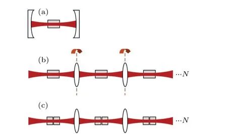
Fig. 1. (a) Conventional OPO cavity, (b) single-pass multi-stage OPG-OPA, (c) single-pass multi-stage OPG-OPA, with walk-offcompensated crystal pairs.
The experimental setup is shown in Fig. 2. A homemade ps pump source is a regenerative amplifier seeded by an SESAM passive mode-locked 1.064 µm Nd:YVO4laser.The measured output power scaling, the pulse train, and the normalized intensity autocorrelation trace of the pump source are plotted in Fig.3.The available average output power of the pump source is 4.9 W,operating at the repetition rate of 10 kHz and the central wavelength of 1064 nm. The pump pulse duration was estimated in Gaussian fit to be~86 ps based on the intensity autocorrelation trace. The beam quality factor ofM2~1.3 was measured by a knife-edge technique. A combination of HWP and TFP is used to systematically control the average power of the pump source. A convex lens(L)is used to focus the pump beam to a waist around 0.28 mm.
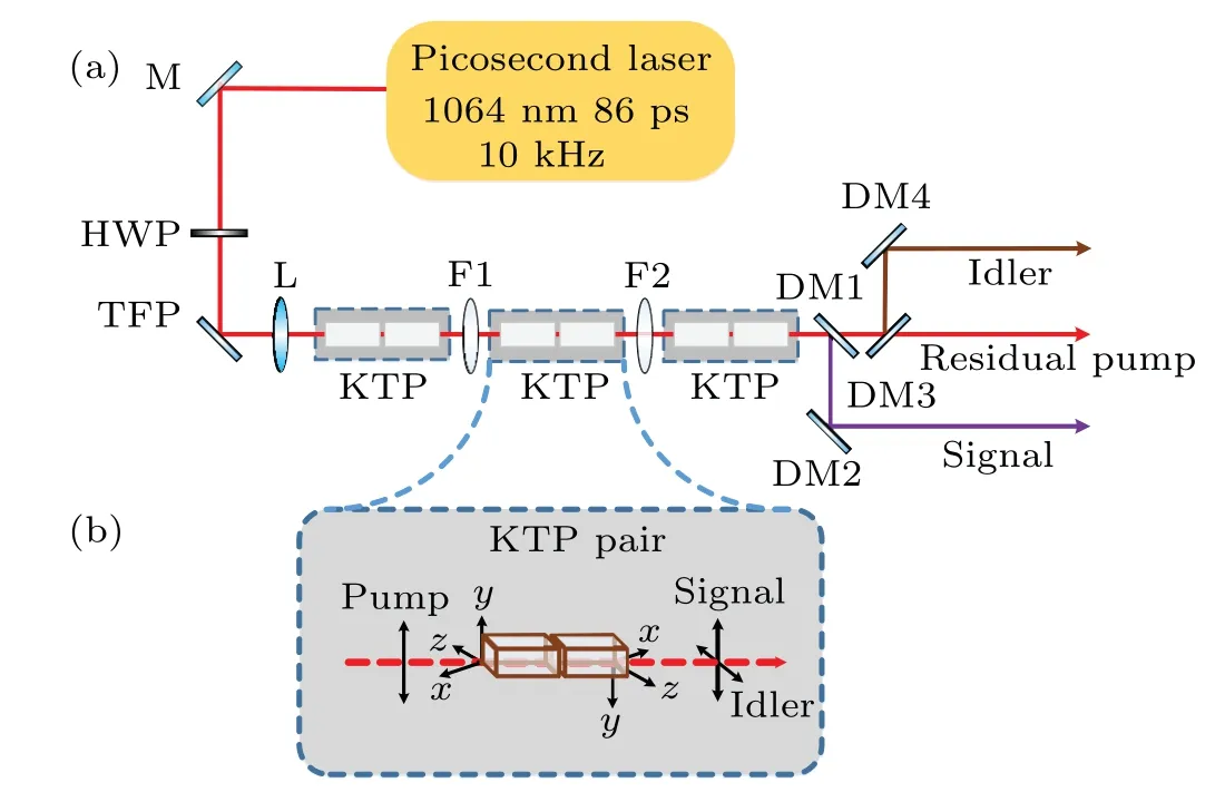
Fig.2.(a)Experimental setup of the single-pass multi-stage OPG-OPA,pumped by a 10 kHz picosecond regenerative amplifier. M:mirrors;L:lens;HWP:half-wave plate;TFP:thin-film polarizer,F1 and F2: CaF2 lenses;DM1,DM2,DM3 and DM4: dichroic mirrors. (b)Layout of a walk-off-compensated KTP pair with the opposite y-axis.
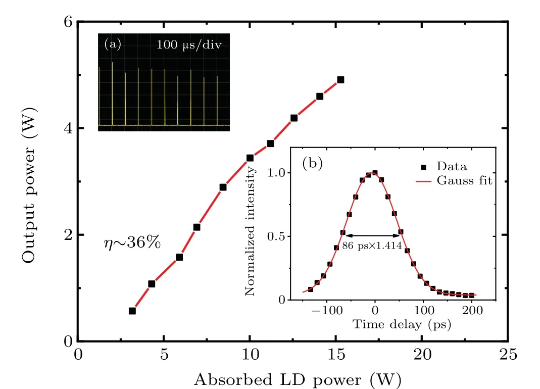
Fig.3. Output power of the pump source as a function of the absorbed LD power. Insets: (a)the pulse train of pump source in a time span of 1ms;(b)measured autocorrelation trace of pump source at 10 kHz and its Gaussian fit.
The single-pass multi-stage OPG-OPA consisted of three walk-off-compensated KTP crystal pairs and two identical CaF2convex lenses with a focal length of 500 mm. Each crystal is the samex-cut type II(θ=61°,φ=0°)with the dimensions of 3 mm×3 mm×20 mm. Every crystal pair is placed in a walk-off compensated configuration with two oppositeyaxis crystals as shown in Fig. 2(b).[26]The pump beam is spolarized light, corresponding to they-axis of crystals. Both end surfaces of crystals were AR-coated for the pump,signal,and idler(AR@1.064µm&1.7µm&2.7µm). The OPO acceptance angle is calculated to be 2.59 mrad·cm. The three KTP crystal pairs were carefully adjusted to make sure the consistency of the gain bandwidth center. Two CaF2convex lenses(F1 and F2)were put between the KTP pairs.The lenses were also AR-coated for the pump, signal, and idler light(AR@1.064µm&1.4-1.7µm&2.7-4.3µm). The GVM between the pump and idler is estimated to be 193 fs/mm,in KTP crystal, resulting in a temporal walk-off length of 445 mm,longer than the 120 mm total length of all crystals.
It is necessary to ensure an appropriate beam size mode matching during the propagation of the pump beam along the single-pass OPG-OPA. The beam propagation process in the single-pass multi-stage OPG-OPA is similar to the process in a cavity. Thus, the stable mode of the single-pass OPG-OPA can be calculated in an assuming cavity. While the interval between the CaF2lenses is optimized to be 80 mm,it is calculated by ABCD matrix that the beam waist of the single-pass OPG-OPA stable mode is~0.277 mm at the middle of KTP pairs,considering the refractive of KTP(~1.748 at 1064 nm)and the beam quality factor of the pump source(~1.3). Then the pump beam is focused to~0.28 mm at the middle of the first KTP pair to match the stable mode,the beam waist would repeatedly appear at the middle of every KTP pair and all the beam waist radius were about 0.28 mm,as shown in Fig.4.
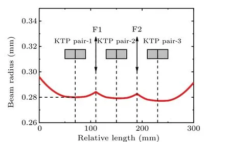
Fig. 4. Calculated beam radius of pump light along the single-pass OPG-OPA.
3. Experimental results
The first and second crystal pairs were failed to be characterized due to no enough output power to be measured owing to the limitation of the available instrument sensitivity at our disposal.The evolution of the average output power of the signal and idler waves as a function of the injected pump power in the three crystal pairs was measured and plotted in Fig.5. The maximum pump power of~3 W was used to avoid the damage of the nonlinear crystals.The threshold was observed to be~1.1 W.It is found that both the signal and idler output power increases linearly with the injected pump power. At the pump power of 3 W,a maximum signal average power of 502 mW at 1.77µm was obtained,corresponding to a signal pulse energy of 50.2 µJ. A signal slope efficiency of~28% and opticalto-optical conversion efficiency of~17% were created. The corresponding idler average power at 2.67µm is 276 mW with a slope efficiency of~13%and optical-to-optical conversion efficiency of 9%. Considering the total output power (signal and idler)of~778 mW under maximum injected pump power of 3 W,the nonlinear conversion efficiency is up to 26%.
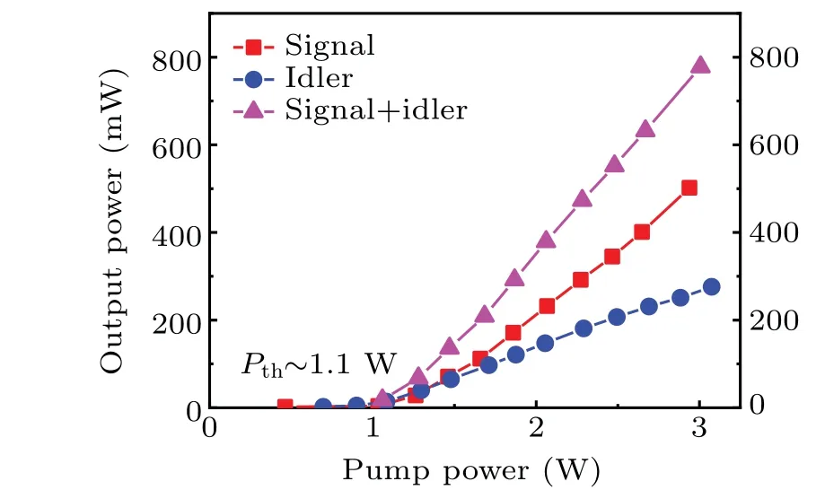
Fig. 5. Average output power of the signal at 1.77 µm (red squares),idler at 2.67µm(blue circles),and signal+idler(magenta triangles)as a function of the injected pump power.
The spectrum of the signal light was measured by an optical spectrum analyzer(Ocean Insight NIRQuest512-2.5,900-2500 nm),and the result is shown in Fig.6. It can be seen that the signal wavelength is centered at~1.77 µm, corresponding to the idler wavelength of 2.67 µm. The signal spectral linewidth displayed is~17 nm. While the spectral linewidth of the signal light may be failed to represent the real linewidth due to the limit of the spectrometer resolution(6.3 nm,25µm slit), the measured spectrum can still indicate a large spectral linewidth of the signal light, which could be mainly attributed to the gain bandwidth in high-gain condition and the divergence of the generated signal and idler beams. Under the high-gain condition,the signal light obtains enough gain near perfect phase matching, resulting in larger spectral linewidth compared with the low-gain condition. The divergence of the generated signal and idler beams causes off-axis optical parametric amplification,also leads to larger spectral linewidth.
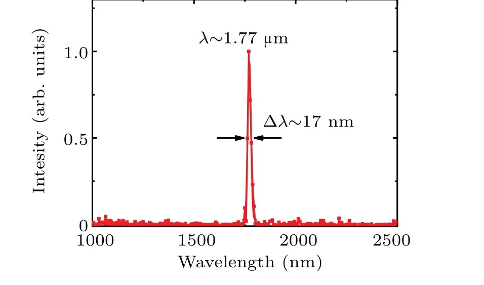
Fig.6. Measured spectrum of the signal light.
Owing to the limitation of our autocorrelator sensitivity,the pulse width of the signal and the idler beams are failed to be measured. Here, the pulse temporal shape was simulated by a numerical model taking into account pump depletion, crystal linear absorption, GVM, GVD, and the energy loss between crystal pairs,[27,28]and the spatial walk-off is ignored because of the adopted walk-off compensated configuration.The coupling equations are solved numerically in the frequency domain using the fourth-order Runge-Kutta method.The seeds of the signal and idler pulse are optical parametric noise generated by the pump pulse,[24]and the energies of the seeding signal and idler are assumed to be single photon energy, respectively. It is assumed that the pump light is a plane wave. The simulated result is shown in Fig. 7. The pump pulse is depleted partly in the center due to the downconversion. The pulse width of both the signal and idler pulse is simulated to be~33 ps, which is narrower than the pump pulse width,originating from the temporal gain narrowing effect. The simulated average output powers of signal and idler light are 531 mW and 356 mW,respectively, which are close to the experimental average powers of the signal and idler of 502 mW and 267 mW, respectively. The pulse centers of the signal and idler are slightly offset the coordinate zero point of the time axis due to the effect of GVM. The output power of the OPG-OPA in four crystal pairs was also simulated to be 443 mW for signal and 233 mW for idler,indicating a decline in the output energy at the four crystal pairs scheme.
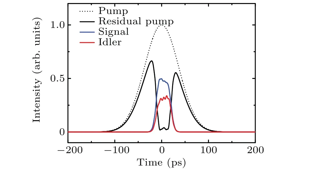
Fig. 7. Simulated pulse temporal shapes in the single-pass OPG-OPA of three crystal pairs.
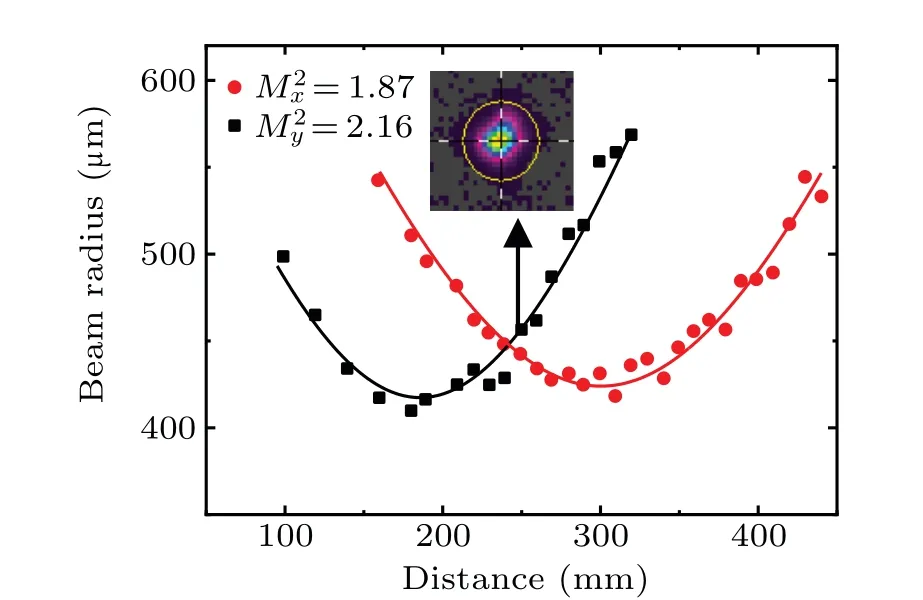
Fig. 8. Beam quality factor M2 measured after filtering out ~40%power. Inset: 2D spatial beam intensity profile.
The beam quality and the intensity distribution of the signal beam at 1.77µm were measured by a beam profiling camera (Ophir Spiricon, PY-III-C-A) as shown in Fig. 8. At the maximum output power, the beam quality factor of the signal wave was measured to beM2x×M2y=2.62×4.58. Moreover, the beam quality factor can be improved toM2x×M2y=1.87×2.16 after filtering out about 40%signal power,adopting spatial filtering technology. The inset of Fig. 8 displays the corresponding two-dimensional (2D) spatial beam intensity profile,exhibiting a good beam quality with Gaussian profile,which is important for applications.
4. Conclusion and perspectives
In summary,we have demonstrated a new management of single-pass multi-stage OPG-OPA to obtain high-energy picosecond sources with high beam quality. The pump beam matches the stable mode of the OPG-OPA.At pump power of~3 W and repetition rate of 10 kHz,the record output powers of the signal and the idler light are 502 mW and 276 mW with pulse energy up to 50.2µJ and 27.6µJ,respectively. The signal wavelength was measured to be~1.77µm,corresponding to the idler wavelength of 2.67 µm. The signal-beam quality factor can be improved to beM2x×M2y=1.87×2.16 after filtering out about 40%signal power.
Acknowledgements
This work was supported by the National Science Foundation for Young Scientists of China (Grant No. 61805259),and Youth Innovation Promotion Association,CAS,and Chinese Academy of Sciences funding (Grant No. ZDRW-KT-2019-4-01).
- Chinese Physics B的其它文章
- Role of compositional changes on thermal,magnetic,and mechanical properties of Fe–P–C-based amorphous alloys
- Substrate tuned reconstructed polymerization of naphthalocyanine on Ag(110)
- Anti-PT-symmetric Kerr gyroscope
- Information flow between stock markets:A Koopman decomposition approach
- Cascading failures of overload behaviors using a new coupled network model between edges
- High efficiency ETM-free perovskite cell composed of CuSCN and increasing gradient CH3NH3PbI3

