Metal substrates-induced phase transformation of monolayer transition metal dichalcogenides for hydrogen evolution catalysis*
Zhe Wang(王喆) and Wenguang Zhu(朱文光)
1Department of Physics,University of Science and Technology of China,Hefei 230026,China
2International Center for Quantum Design of Functional Materials(ICQD),Hefei National Laboratory for Physical Sciences at the Microscale,and Synergetic Innovation Center of Quantum Information and Quantum Physics,University of Science and Technology of China,Hefei 230026,China
3Key Laboratory of Strongly-Coupled Quantum Matter Physics,Chinese Academy of Sciences,School of Physical Sciences,University of Science and Technology of China,Hefei 230026,China
Keywords: transition metal dichalcogenides,phase transformation,hydrogen evolution reaction,density functional theory
1. Introduction
Transition metal dichalcogenides (TMDs), as a class of representative layered materials,received tremendous research attention in recent years owing to their rich electronic, optical, and catalytic properties.[1-5]In the atomic structures of TMDs,each monolayer contains a transition-metal layer sandwiched between two chalcogenide layers. The variation in the stacking geometry of the three atomic layers may leads to different phases, typically a trigonal prismatic phase (1H) and an octahedral phase(1T).An intriguing feature of monolayer TMDs is their electronic structures critically depending on the atomic-layer stacking geometry. For group-VI-element TMDs MoS2, its trigonal prismatic phase is a good semiconductor with a sizable bandgap,whereas its octahedral phase becomes metallic. This transition can be qualitatively understood as the difference in the splitting and filling of the transitionmetal d-orbital dominated energy bands due to the different crystal symmetries and coordination environments of the two phases.[6]Such distinct electronic structures may in turn lead to disparate physical and chemical properties,such as catalytic activity. Although both 1H- and 1T-MoS2has shown to be catalytic for the hydrogen evolution reaction(HER),the active sites are solely limited at the edges in the 1H phase[7,8]but include the whole basal plane of the 1T phase.[9-14]However,for pristine MoS2,the 1T phase is energetically less stable than the 1H phase. Therefore,to enhance the catalytic performance of MoS2, it is highly desirable to increase the ratio of the 1T phase via tuning the relative stability of the two phases.
In this effort, there have been extensive attempts to induce structural phase transformation of group-VI elements Mo- and W-based TMDs and stabilize the 1T phase.[15-18]The main strategy of these research is to dope extra electrons into the TMDs via, for example, Re doping[19]and alkali ion intercalation.[20-23]Some other approaches including mechanical stress[24]and metal substrates[25-27]have also been reported. However, the stability of the obtained 1T phase still needs to be improved.[28,29]In addition, for the catalytic purpose, it is also vitally important to leave the active sites open for chemical reaction.
In this work, we use first-principles density functional theory (DFT) calculations to investigate the effects of three low-work-function metal substrates including Ti, Zr, and Hf on the structural,electronic,and catalytic properties of monolayer MoS2and WS2. A distorted 1T phase,named 1T'phase,is identified to become energetically most stable in the presence of the metal substrates. The electronic structure analysis indicates that the metal substrates donate electrons to the MoS2and WS2monolayers,leading to the phase transformation. Meanwhile, the presence of the substrates also significantly reduces the kinetic barriers of the phase transformation. In addition, Gibbs free energy calculations suggest that the HER catalytic activity on the top surface of the 1T'-MoS2monolayers is still largely preserved as placed on the Zr or Hf substrate.
2. Computational methods
The first-principles DFT calculations were performed using the Viennaab initiosimulation package(VASP).[30]Core and valence electrons were described using the projectoraugmented wave (PAW) method.[31,32]The exchange and correlation functional was treated using the Perdew-Burke-Ernzerhof (PBE) parametrization of generalized gradient approximation(GGA)for structural relaxations and total energy calculations.[33]The energy cut-off of the plane wave basis was set to 300 eV. Electronic minimization was performed with a tolerance of 10−4eV, and ionic relaxation was performed with a force tolerance of 0.01 eV/˚A on each ion. A vacuum region more than 15 ˚A was used to ensure decoupling between neighboring slabs. AΓ-centered 18×18×1 Monkhorst-Pack[34]k-mesh was used fork-point sampling.The climbing image nudged elastic band(CI-NEB)method[35]was used to determine the minimum energy pathways of the various kinetic processes and their transition states with five intermediate geometries(images)interpolated between the initial and the final states, and the transition states were finally achieved by the optimized central image. In addition,the van der Waals corrections was included as parameterized in the semiempirical DFT-D3(BJ)method.[36,37]

3. Results and discussion
3.1. Structures and structural stability of TMDs with substrates
Monolayer 1H-and 1T-MoS2(WS2),as shown in Fig.1,are both composed of three layers of atoms, and each atomic layer contains only one element stacking in a sequence of SMo(W)-S.All the atoms in each atomic layer are arranged into a close-packed triangular lattice. The difference between the two phases is their vertical stacking geometries. As shown in Figs.1(b)and 1(d),respectively,the 1H phase follows an ABA stacking sequence,while the 1T phase forms an ABC stacking sequence. For freestanding MoS2and WS2monolayers, the 1H phase is energetically most stable with total energy differences of approximately 0.8 eV from the DFT calculations. In addition, the freestanding 1T-MoS2and 1T-WS2monolayers are metastable. A more stable phase,named 1T'phase,can be derived from the high-symmetry 1T phase via local structural distortion, ending up with a 2×1 superstructure and a small band gap opening(Figs.1(e)and 1(f)).The calculated total energy of the 1T'phase is 0.25 eV/MoS2(0.32 eV/WS2) lower than that of the 1T phase,whereas it is still higher than that of 1H phase by around 0.6 eV for monolayer MoS2(WS2).
Threehcpmetals, Ti, Zr, and Hf, are chosen to investigate the effects of low-work-function metal substrates on the structural stability and catalytic activity of monolayer MoS2and WS2. The lattices of the (0001) surface of these metals(Figs. 1(g) and 1(h)) can nicely match with the in-plane lattices of MoS2and WS2. The calculated lattice constants of MoS2and WS2in different phases and the metals along with their lattice mismatches are summarized in Table 1. The lattice mismatches between MoS2(WS2)and Ti,Zr,and Hf are~7.8%,~1.5%,and~0.4%,respectively.In the calculations of the combined systems, the lattices of MoS2and WS2are adjusted to match the optimal lattices of the metal substrates,unless otherwise specified.

Table 1. Calculated lattice constants of MoS2 and WS2 in different phases and the metal substrates along with their lattice mismatches.

Fig.1. Atomic structures of monolayer MoS2 (WS2),with Mo(W)atoms in red and S atoms in yellow,and the metal substrates,with the metal atoms in blue. (a)-(b)1H phase. (c)-(d)1T phase. (e)-(f)1T' phase. (g)-(h)Ti,Zr or Hf substrate. The sites of the metal atoms on the surface and second layer,and the hollow site are defined as A,B,and C,respectively.
To determine the most favorable stacking structures of the monolayer MoS2and WS2on the metal substrates, various possible high-symmetry stacking configurations are considered.For the(0001)surface terminated slabs of hcp metals,the atoms in each layer also form a triangular lattice, and the vertical stacking follows an ABAB sequence. To label different stacking configurations of the TMDs monolayers on the metal substrates,we denote the surface layer of the metal substrates as site A and the second layer as site B. The stacking configurations of the TMDs monolayers, as shown in Fig. 2,can be labeled asXY(X,Y=A,B,C),whereXandYcorrespond to the positions of the bottom S layer and the Mo atom with respect to the underlying metal substrate, respectively.The calculation results of the MoS2/Hf system are summarized in the table of Fig.2, which shows that for the 1H phase, the most favorable stacking configuration is BA, while it is CA for the 1T and 1T'phases. More importantly, in contrast to the freestanding monolayer,the most stable structure of MoS2becomes the 1T'phase in the presence of the Hf substrate.
To further examine the validity of our calculations, we thoroughly investigated the relative stability of various structural phases of MoS2and WS2on Ti, Zr, and Hf substrates with different settings of the lattice parameters using the optimal lattice constant of the metal substrate or the 1H-or 1TTMDs monolayers. The calculated relative energies of different phases of MoS2and WS2in the two most likely configurations CA and BA on the metal substrates are summarized in Table 2. The results clearly confirm the above conclusion.The 1T'/1T phase of MoS2and WS2monolayers are always energetically more favorable than the 1H phase on these metal substrates. In the cases of using Ti as the substrate, the 1T'phase becomes unstable exclusively as the lattice parameter is set to the lattice constant of Ti,because of a large compressive strain imposed on the TMDs monolayers. Instead, the structures were stabilized into the 1T phase,which still have lower energies than the 1H phase. Therefore, the proposed metal substrates can effectively reverse the relative thermaldynamic stability of monolayer MoS2and WS2from the 1H phase for the freestanding case to the 1T'/1T phase.

Fig.2. Atomic structures of various possible high-symmetry stacking configurations and their relative energies in the MoS2/Hf system. The different stacking configurations are labeled as XY (X,Y =A, B, C), where X and Y correspond to the positions of the bottom S layer and the Mo atom with respect to the underlying metal substrate,respectively. All data are the energies per MoS2.
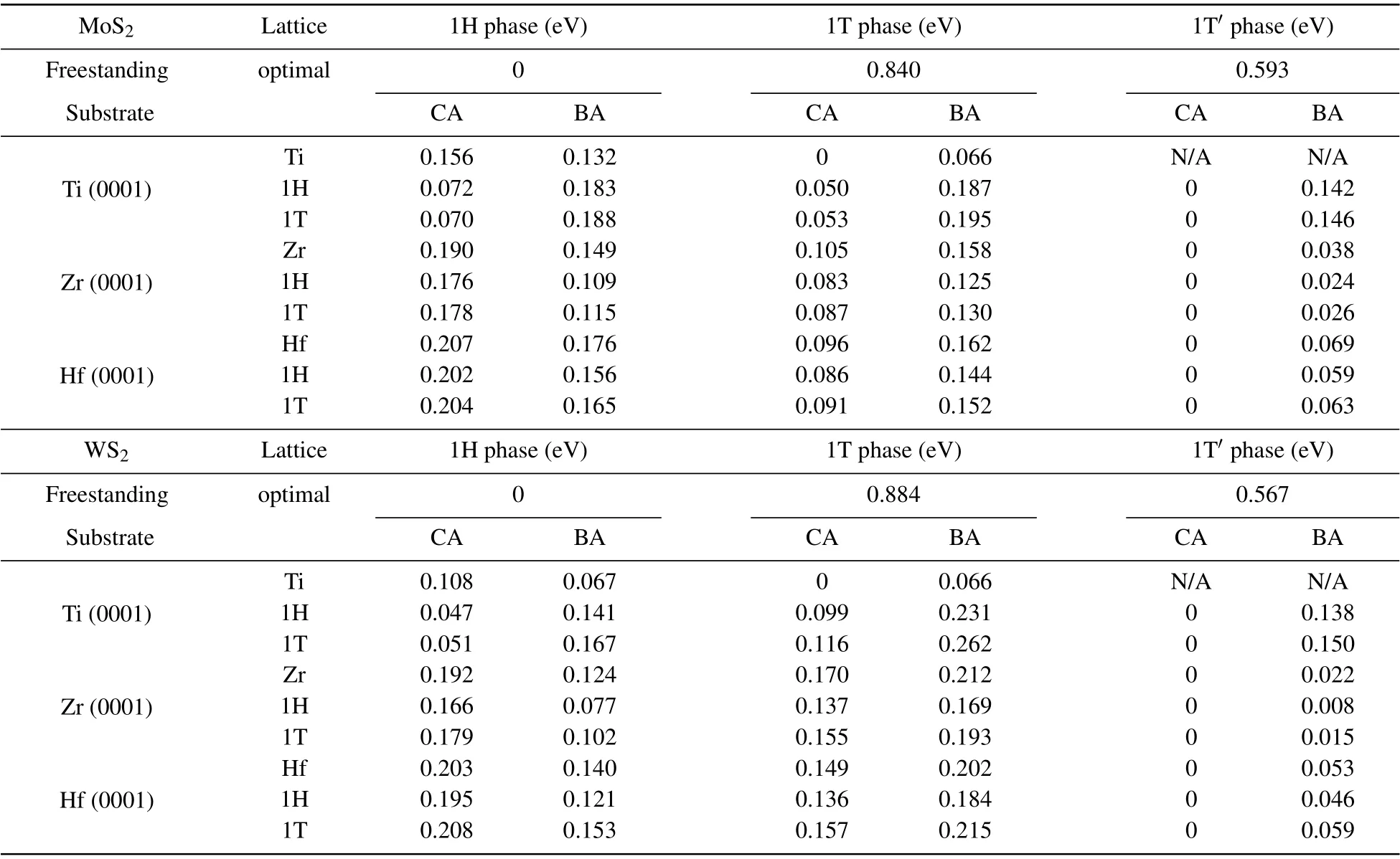
Table 2. Relative energies of various structural phases of MoS2 and WS2 with and without the metal substrates. The combined systems with different settings of the lattice parameters using the optimal lattice constant of the metal substrate or the 1H- or 1T-TMDs. The energies of each row are relative to the energy of the most stable structure in this row. All data are the energy per MoS2 or WS2.
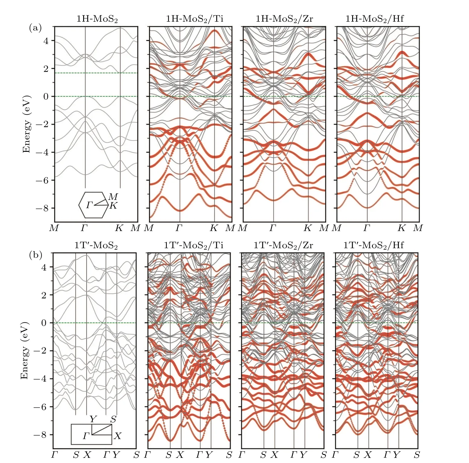
Fig.3. Band structures of(a)1H-MoS2 and(b)1T'-MoS2 with and without the metal substrates,where the MoS2 derived energy bands in the combined systems are highlighted in red.
The underlying mechanism of the metal substrateinduced phase stability reversal can be revealed from electronic structure analysis. Figure 3 shows the calculated band structures of 1H-and 1T'-MoS2monolayers on the three metal substrates,respectively,where the MoS2derived energy bands are highlighted in red. For comparison, the calculated band structures of freestanding MoS2monolayers in the 1H and 1T'phases are also illustrated in Fig.3.Although the energy bands of MoS2are modified to a certain extent in the combined systems due to the hybridization with the metal substrates, the positions of the original band edges of freestanding MoS2can still be identified. From these plots,it can be seen that for both 1H and 1T'phases,the Fermi levels of the combined systems were always moved up into the original conduction bands of MoS2, indicating the existence of effective electron transfer from the metal substrates to the MoS2monolayers. This observation is also consistent with our initial design of taking advantage of a low-work-function metal substrate to donate electrons into TMDs so as to reverse the relative stability from the 1H phase to the 1T'/1T phase.
3.2. Kinetics of phase transformation
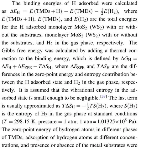
Kinetics is also a key factor for the feasibility of phase transformation. In this regard,we investigated the kinetic processes and calculated the energy barriers of MoS2and WS2monolayers transforming from the 1H phase to the 1T phase in the presence of the metal substrates. Since the rate-limiting processes for the 1H phase to the 1T and 1T'phases are essentially the same,[39]we use the 1T phase as the final state to simplify the calculation. The difference between 1H and 1T phases is the vertical alignment of the two chalcogen layers. The phase transformation thus can be achieved by simply moving one of the chalcogen layers collectively with respect to the other two atomic layers. However, when the TMDs monolayers placed on the metal substrates, the top and the bottom chalcogen layers become inequivalent, and thus there are two possible phase transformation pathways from the 1H phase to the 1T phase. For the 1H phase, the positions of the top and bottom S layer are both at the site B (defined in Fig. 1) with respect to the underlying metal substrate. The phase transformation from the 1H phase to the 1T phase can be achieved by simply moving the top or the bottom S layer from the site B to the site C. Figures 4(a) and 4(c) show the calculated energy profiles of the kinetic processes involving the moving of the top S layer. Compared with the cases of freestanding monolayers, the energy barriers are effectively reduced from~1.6 eV to~1.2 eV.More interestingly,in the kinetic process involving the moving of the bottom S layer as shown in Figs. 4(b) and 4(d), the energy barriers are further substantially reduced to~0.7 eV. For both cases, the optimized transition states correspond to the moving S atoms located nearly at the bridge sites of the central Mo/W layer.The energy barriers to move the bottom S layer are smaller than the barrier of a freestanding monolayer MoS2transforming from the 1T'phase to the 1H phase (~0.9 eV).[39]Such a 1T'to 1H phase transformation has been demonstrated to be experimentally accessible for MoS2.[28,29]All these results indicate that the proposed metal substrates can effectively facilitate the phase transformation of adsorbed MoS2and WS2monolayers from the 1H phase to the 1T'/1T phase.
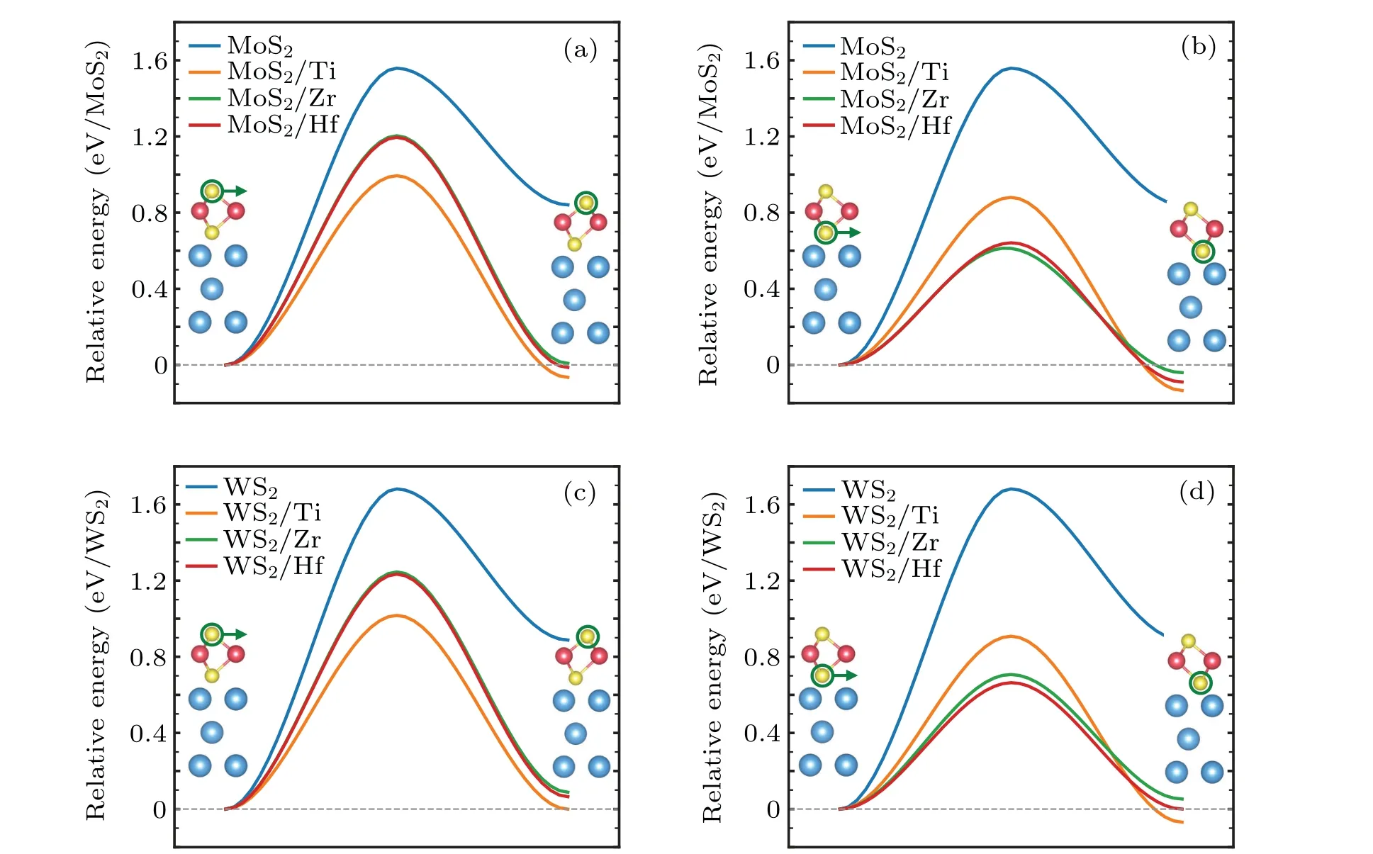
Fig.4. Two possible phase transformation pathways from the 1H phase to the 1T phase. (a)MoS2 with the moving of the top S layer,(b)MoS2 with the moving of the bottom S layer,(c)WS2 with the moving of the top S layer,(d)WS2 with the moving of the bottom S layer. In all plots,the green circles and arrows attached to S atoms indicate the moving atom and the direction of atomic motion during the process of the phase transformation.
3.3. Substrate effects on the hydrogen evolution reaction
We next investigate the catalytic activity of the 1T'-MoS2and 1T'-WS2monolayers with the support of the metal substrates. Different from the 1T'phase achieved by ion intercalation, the top surface of the TMDs monolayers is still freely exposed for the chemical reaction. In addition,the metal substrates can be used directly as an electrode. Therefore, such a combined system is an ideal setup for the electrocatalytic HER.
It has been commonly recognized that the catalytic performance of an HER is essentially dictated by the Gibbs free energy (∆GH) of H adsorption on the catalysts with a value around zero being optimal.[40]For this reason and simplicity,we calculated the Gibbs free energies of atomic hydrogen adsorption on the metal substrate supported MoS2and WS2monolayers with 4×4 supercells as a measure. The calculation results are summarized in Table 3. For freestanding MoS2, the basal plane of the 1H phase is catalytically inert,∆GH=1.92 eV, while the 1T'phase is active, with a ∆GHof 0.19 eV. In the presence of the metal substrates, the ∆GHof 1H-MoS2is reduced to~1.5 eV, but still too large for the HER.For 1T'-MoS2,although their ∆GHare generally increased by the metal substrates, the ∆GHof 1T'-MoS2with Zr and Hf substrates are 0.48 eV and 0.56 eV, respectively,which are still comparable to the ∆GHof Au (~0.5 eV).[41]For the case of 1T'-MoS2/Ti, the ∆GHincreases to 1.30 eV,which may be related to the large lattice mismatch. For the cases of 1T'-WS2, their ∆GHare always larger than those of 1T'-MoS2on the same metal substrate,among which the 1T'-WS2/Zr system has the lowest ∆GHas large as 0.75 eV.To sum up,MoS2with Zr or Hf as the substrate may be considered as a promising HER catalyst.
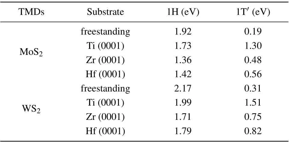
Table 3. The Gibbs free energy(∆GH)of the hydrogen evolution reaction for 4×4 TMDs supercell with and without the metal substrates at 1/16 H coverage.
Overall, the metal substrates reduced the ∆GHof the 1H phase and increased the ∆GHof the 1T'phase. According to previous studies on freestanding TMDs,[42,43]the strength of H adsorption on the surface of TMDs is determined by the ability of the surface chalcogen atoms to attract electrons from H, and ∆GHclosely correlates to the position of the lowest unoccupied state of the catalyst (the conduction band minimum for semiconductors or the Fermi level for metals) with respect to the vacuum level. To examine its validity in our systems,we plot ∆GHversusthe lowest unoccupied state positionεLUS, which is calculated as the energy difference of the vacuum level and the conduction band minimum for freestanding MoS2(WS2) or the Fermi level for MoS2(WS2) in the presence of the metal substrates. As shown in Fig. 5, an obvious linear correlation is revealed, which in consistent with the previous work,[42,43]and also indicates thatεLUSis still a significant determinant for the HER of MoS2(WS2)on the metal substrates. In addition,compared with the freestanding monolayer MoS2(WS2), the values ofεLUSincrease for the 1T'phase and decrease for the 1H phase in the presence of the metal substrates,which can be attributed to the interaction and charge transfer between the MoS2(WS2) and the metal substrates.
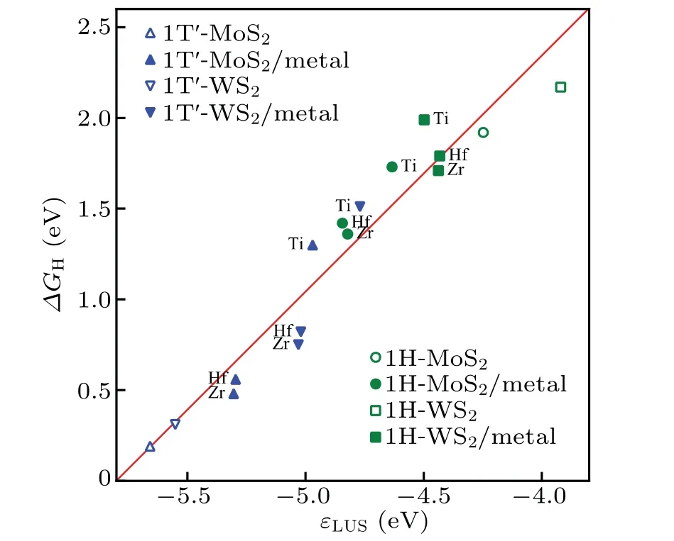
Fig.5.Correlation between the Gibbs free energy ∆GH and the lowest unoccupied state εLUS,which is calculated as the energy difference of the vacuum level and the conduction band minimum for freestanding MoS2(WS2)or the Fermi level for MoS2 (WS2)in the presence of the metal substrates.
4. Conclusions
In summary,we have demonstrated from both energetics and kinetics aspects that low-work-function metals Ti,Zr,and Hf can be used as a functional substrate to effectively make monolayer MoS2and WS2undergo structural transformation from the 1H phase to the 1T'/1T phase,based on DFT calculations. In addition,1T'-MoS2with Zr or Hf as a substrate may function as a potential catalyst for the HER.
Acknowledgment
Computational support was provided by National Supercomputing Center in Tianjin.
- Chinese Physics B的其它文章
- Erratum to“Floquet bands and photon-induced topological edge states of graphene nanoribbons”
- Viewing the noise propagation mechanism in a unidirectional transition cascade from the perspective of stability*
- Nonlinear signal transduction network with multistate*
- Optical strong coupling in hybrid metal-graphene metamaterial for terahertz sensing*
- Any-polar resistive switching behavior in Ti-intercalated Pt/Ti/HfO2/Ti/Pt device*
- Magnetic two-dimensional van der Waals materials for spintronic devices*

