Dynamics analysis of a 5-dimensional hyperchaotic system with conservative flows under perturbation∗
Xuenan Peng(彭雪楠), Yicheng Zeng(曾以成), and Qi Xie(谢奇)
School of Physics and Optoelectronic Engineering,Xiangtan University,Xiangtan 411105,China
Keywords: perturbation method,coexistence hidden chaotic sea,FPGA realization
1. Introduction
Chaos-based encryption algorithms have been widely reported.[1–3]However,chaotic attractors can be reconstructed by the delay embedding of captured data. Thus, the encryption systems employing dissipative chaotic oscillator are vulnerable to deciphers from attackers. In contrast, conservative chaotic systems have conserved phase space volumes and their integer dimension equals the system’s dimension,[4]which are a great candidate for encryption. Therefore,obtaining a conservative system with more complex dynamics can attract a number of researchers in recent years. A high dimensional generalized conservative Hamiltonian system with multi-stable was proposed.[5]Coexisting conservative flows generated by 4D inductor-capacitor circuits were designed.[6]Similarly, another conservative system, constructed by a meminductor and a capacitor, with self-reproducing chaos was proposed.[7]From the perspective of system equilibrium, a chaotic oscillator can be divided into hidden and self-excited ones.[8]Since there is no systematic method to locate the hidden chaotic flow,[9]dynamics analysis of hidden chaotic systems is favored by researchers. A simple method to create a hidden chaotic system is adding micro-perturbation in a selfexcited system. Wei modified Sprott’s system via adding a constant parameter.[10]A hidden chaotic system with only one stable equilibrium was discovered by Phamet al.using the tiny perturbation method.[11]A memristive chaotic oscillator generating hidden extreme metastability was discovered by introducing micro-perturbation into an original system.[12]It is obvious that a high-dimensional conservative system having hidden multi-stability can be well applied in real world such as random-number generators and information encrypting systems.[13]Inspired by these works,perturbation method is employed to modify a 5D conservative chaotic system. Thence, a novel model without equilibrium is constructed. Then, via adjusting perturbation magnitude and parameters, various dynamics, such as coexisting conservative flows,chaotic sea and hyperchaotic attractor,can be observed in this novel system. Furthermore,the complexity of the novel system is better than the original one. Thus,the real-world application ability of the system is improved by employing the tiny perturbation method. The rest of this paper is organized as follows: In Section 2, the chaotic model is proposed. Its dynamics are analyzed in Section 3. The field programmable gate array (FPGA) realization of chaotic models is displayed in Section 4. Finally,some conclusions are included.
2. Chaotic model
The novel 5D chaotic system is expressed as follows:

wherex,y,z,uandware state variables;ais the system parameter;crepresents perturbation. Setting the right-hand side of system(1)to zero,the equations can be expressed as
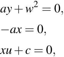

When perturbationc= 0 and resolving the equations, line equilibria are (0, 0, 0,R, 0), whereRdenotes real number.Then,adjusting value ofcto a nonzero number,Eq.(2)cannot obtain real solutions. Consequently, chaotic flows created by system(1)are all hidden. Linearizing the right hand of system(1),the Jacobian matrixJcan be obtained as follows:

According to Eq. (3), existence ofcdoes not change the expression of Jacobian matrix. Thus,dynamics of system(1)are not greatly affected whencis micro-value.

Fig.1. Dynamic behaviors of the modified system. (a)Bifurcation diagram versus parameter a. (b)Lyapunov exponent spectrum.
3. Coexisting conservative flows and complexity analysis
Selecting the value of perturbationc=0.001 and parameterb=1,the bifurcation diagram varying withais displayed in Fig. 1. There are three coexisting hidden flows in bifurcation diagram when the value of parametera>1.5. The relation between initial conditions and color of images is defined as follows: initial conditions(1, 1, 1, 1, 1)are corresponding to khaki image;initial conditions(−1,−1,1,−1,−1)are corresponding to green image;initial conditions(−1,−1,−1,1,1)are corresponding to blue image. To obtain concise results,the value of parameterais designated as 2. Phase portraits of coexisting chaotic flows inx–yplane are plotted in Fig.2.

Fig.3. Phase portraits of the system(a)in x–z plane,(b)in x–u plane,and(c)in x–w plane.
The phase portrait projections in other planes are shown in Fig. 3. Moreover, with increasing parametera, hyperchaotic sea,chaotic sea and quasi-period state can be observed when initial conditions are (1, 1, 1, 1, 1). These dynamic behaviors can be further explained by the Lyapunov exponent spectrum shown in Fig.1. With increasing parametera,the maximum Lyapunov exponent decreases gradually. Whena=2.5, the maximum Lyapunov exponent is close to zero.Quasi-period state of system(1)occurs ina=2.55,the corresponding phase portrait is shown in Fig. 2. Whena=3, the Lyapunov exponents are 0.007,0.003,0,−0.003 and−0.007,invariant tori created by system(1)are plotted in Fig.2.
Then,we consider to adjust magnitude of perturbationc.The Lyapunov exponent spectrum varying withcunder the condition (−1−1−1 1 1),a=2 andb=1 is displayed in Fig. 4. Increasing perturbationcwill result in the fact that the sum of Lyapunov exponents gradually becomes less than zero. Accordingly, the phase space volume of system(1)becomes non-conservative. Correspondingly,conservative flows are substituted by hyper-chaotic attractor.In addition,the Lyapunov exponent spectrum is almost symmetric aboutc=0.This means that system dynamics behavior is only related to the magnitude of disturbance, instead of the sign. Complexity characteristic of chaotic system(1)under different perturbations is tested using the shannon entropy (SE) complexity method.[14]The relation between SE value and perturbation magnitude is shown in Fig. 4. Obviously, within a certain range,the system has a larger SE value when the perturbation magnitude increases. However, excessive disturbance leads to Lyapunov exponents unbalanced,and affects the volume of system phase space. Whenc=0.1,the SE value of the modified system is 0.15 larger than the original one. Whenc=5,the SE value is only 0.07 greater thanc=0.1.The sum of Lyapunov exponents is−0.0001 whenc=0.1. Therefore,settingcto 0.1,the system has an ideal hyper-chaotic state and a better SE value. The phase portrait of the system under this condition is shown in Fig.4. In addition,0–1 test results of system(1)whenc=0 andc=0.1 are shown in Fig.5. According to figures, these systems all exhibit the irregular Brownian motion inp–splane. As compared with the original system, the system under perturbation has more vast motion scale. This indicates that the novel system has better randomness.

Fig.4. Dynamics and complexity analysis: (a)the Lyapunov exponent spectrum,(b)the SE spectrum,(c)the phase portrait when c=0.1.

Fig.5. The 0–1 test results(a)when c=0 and(b)when c=0.1.
4. FPGA implementation
4.1. Digital oscillator
As compared with analog circuits, digital circuits have more benefit such as consuming low resources, fast calculation speed, and low power consumption.[15]Commonly used digital chips are microcontrollers,[16]digital signal processing (DSP) chips[17]and FPGA chips.[18–20]In this section, a digital chaotic oscillator is designed by a Xilinx FPGA chip.The Runge–Kutta-4(RK-4)numerical method and 32-bit fixed point number (1-bit sign part, 7-bit integer part and 24-bit decimal part) are employed to realize this work. In general,researchers coded a chaotic system in an FPGA chip using state machine and DSP builder.[21,22]A chaotic system without complex nonlinear terms and trigonometric function can be easily constructed by the DSP builder model. Yet,the state machine method is applicable to almost every chaotic system.The state machines to implement 5d conservative system include ten states:S0–S9. Here,S0–S4: calculate the differential equation;S5–S7: implement the RK-4 numerical method;S8:add a positive offset into the results generated byS7;S9: truncate 32-bit outputs to 14-bit for adapting digital to analog converter(DAC)input. The top-level register transfer level(RTL)diagrams and timing analysis are shown in Fig.6.
There are two modules in the top-level diagram: phase locked loop(PLL)and chaotic oscillator. PLL module is used to create a 100 MHz system clock, and the main work of the chaotic oscillator is running state machineS0–S9.

Fig.6. FPGA implementation: (a)FPGA RTL diagram,(b)timing analysis,(c)state machine chart.
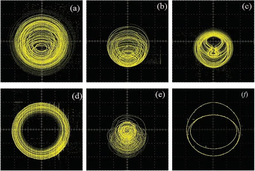
Fig.7. Experimental results. (a)Coexisting chaotic flow under initial conditions(1,1,1,1,1)(1 V per scale). (b)Coexisting chaotic flow under initial conditions(−1,−1,1,−1,−1)(1 V per scale). (c)Coexisting chaotic flow under initial conditions(−1,−1,−1,1,1)(1 V per scale). (d)Conservative flows when a=3(1 V per scale). (e)Hyper-chaotic flows when c=0.1(5 V per scale). (f)Quansi-period state(1 V per scale).
The output signals of FPGA chip are four 1-bit signals,i.e.,ws1,ws2,daclk1 and daclk2,and two 14-bit signals,i.e.,xandy. The first four signals are the driving signals of the 14-bit AN9767 DAC chip. According to timing analysis, the time interval between two iterations is merely 310 ns. That means finishing one iteration costing 31 clock periods in the RK-4 numerical method. While the Euler method cost 8 clock periods, the RK-2 numerical method cost 14 clock periods.Considering the precision issue of these two methods,we still use the RK-4 numerical method to realize the chaotic oscillator. The total resources consummation is displayed in Table 1.The FPGA experimental results are visualized by an oscilloscope as shown in Fig.7.

Table 1. Recourse consummation.
4.2. Pseudo random number generator realization on FPGA
Chaos-based RNG obtaining high attract for their application, it can be designed by 2D maps[26]or other chaotic oscillators.[27,28]The proposed pseudo random number generator (PRNG) is constructed by the following step. Step 9 in state machine is truncated for 32-bit output to 14-bit output for fitting the input of DAC.The normal truncated range is 25th bit to 12th bit, which contains 2-bit integer part and 12-bit decimal part. In this subsection, we change the truncated range from[25th bit–12th bit]to[18th bit–5th bit].This means that we can merely select the last decimal part in chaotic sequencesxandy. Then we can use the XOR operation on these two chaotic sequences and output the operation results. The specific truncation range of data and flow chart of PRNG are shown in Fig.8.
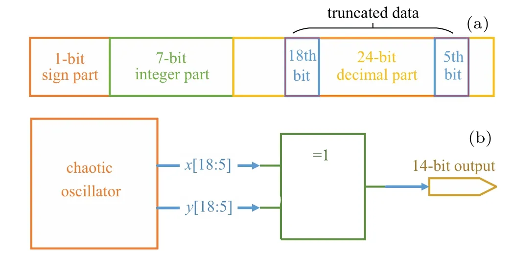
Fig. 8. (a) Schematic diagram of truncating data. (b) Flow chart of PRNG.
Then,we record over 750000 results(total 10500000-bit data)and divide them into 100 groups to test their randomness.The test tool is National Institute of Standards and Technology(NIST)Special Publications(SP)800–22 testing suites. This suit tests 15 different indices about bitstream randomness. If the bitstream is random,the calculatedP-value will be higher than the initial reference value 0.01. The final test results are displayed in Table 2, which indicates that the bitstreams pass the statistical tests of the NIST test suite. This tests prove the possible application of the proposed PRNG to secure systems.
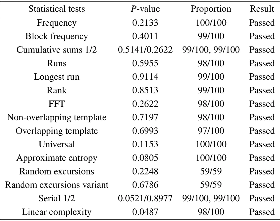
Table 2. NIST suite testing results.
5. Conclusion
In summary, a 5D conservative system is modified using a perturbation method. Due to the novel model without equilibrium, the chaotic flows obtained by this system are all hidden. According to the bifurcation diagram, the model has three coexisting chaotic seas under different initial conditions.Simultaneously,when initial conditions are chosen as(1,1,1,1,1),abundant chaos phenomena under different parameteracan be observed. After that,the effects between dynamics and perturbation are analyzed. The results show that perturbation indeed not only increases the complexity of the system, but also affects the phase space volume. Finally,this model is realized by an FPGA chip.This digital oscillator utilizes little resource and has low power consumption and high through puts.Moreover,a PRNG based on this digital oscillator is designed.The evaluation of NIST SP800-22 testing suite confirms the randomness of the produced chaotic sequences, enabling the possible application of the proposed PRNG to secure systems.
- Chinese Physics B的其它文章
- Physical properties of relativistic electron beam during long-range propagation in space plasma environment∗
- High winding number of topological phase in non-unitary periodic quantum walk∗
- Widely tunable single-photon source with high spectral-purity from telecom wavelength to mid-infrared wavelength based on MgO:PPLN∗
- Control of firing activities in thermosensitive neuron by activating excitatory autapse∗
- Adaptive synchronization of chaotic systems with less measurement and actuation∗
- Application of the edge of chaos in combinatorial optimization∗

