Revealing the A1g-type strain effect on superconductivity and nematicity in FeSe thin flake∗
Zhaohui Cheng(程朝晖),Bin Lei(雷彬),Xigang Luo(罗习刚),2,Jianjun Ying(应剑俊),3,Zhenyu Wang(王震宇),3,Tao Wu(吴涛),2,3,5,†,and Xianhui Chen(陈仙辉),2,3,4,5
1CAS Key Laboratory of Strongly-coupled Quantum Matter Physics,Department of Physics,University of Science and Technology of China,Hefei 230026,China
2Hefei National Laboratory for Physical Sciences at the Microscale,University of Science and Technology of China,Hefei 230026,China
3CAS Center for Excellence in Superconducting Electronics(CENSE),Shanghai 200050,China
4CAS Center for Excellence in Quantum Information and Quantum Physics,Hefei 230026,China
5Collaborative Innovation Center of Advanced Microstructures,Nanjing University,Nanjing 210093,China
Keywords:iron-based superconductors,superconductivity,electronic nematicity,strain effect
Electronic nematic phase,in which the rotational symmetry is broken,exhibits a twist with superconductivity in the electronic phase diagram of iron-based superconductors(IBSCs).[1]Many experiments have already shown conclusive evidences for the electronic nematicity in IBSCs,including anisotropic transport,angle resolved photoemission spectroscopy(ARPES),scanning tunneling microscopy(STM),neutron scattering and so on.[2]So far,although the existence of electronic nematicity in IBSCs is well-established,[3–5]the underlying mechanism and its exact role on the superconducting pairing are still mystery and under hot debate.[1,6,7]Most of the existing experimental results support a direct competition between nematic order and superconductivity in the electronic phase diagram.[8,9]Since the nematic order is tightly twisted with a stripe-type antiferromagnetic order in the iron-pnictide family,[10–12]the competition between the nematic order and the superconductivity is widely believed to stem from the competition between antiferromagnetic order and superconductivity.[8,9]In this case,the nematic order is even considered to be driven by stripe-type spin fluctuations.[1,5,13–16]However,in iron-selenides family such as FeSe1−xSxsystems,there is no direct evidence for the competition between nematic order and superconductivity.[17,18]Interestingly,the stripe-type antiferromagnetic order is also decoupled with nematic order in the electronic phase diagram,which leads to an alternative scenario for electronic nematicity due to orbital order,[19,20]e.g.,the ferro-orbital order.Moreover,orbital fluctuations are also considered to mediate an s++superconducting pairing.[21]So far,the origin of the electronic nematicity and its role on superconductivity are still highly controversial in iron-selenides family.[1,6,7,21,22]
As a conjugate field for electronic nematicity,strain can be used to manipulate the electronic nematicity,[3–5,24,25]which is helpful to elucidate the relationship between electronic nematicity and superconductivity.[26,27]Recently,a dominant B1g-type strain effect on superconductivity has been revealed in the underdoped Ba(Fe1−xCox)2As2.[24,25]With further electron doping,an A1g-type instead of B1g-type strain effect appears and becomes dominant in the overdoped Ba(Fe1−xCox)2As2.[28,29]These results strongly support a significant role of electronic nematicity on superconductivity.Then,a natural question is whether a similar B1g-type strain effect could be also observed in iron-selenides family or not,which would be helpful to further understand the role of electronic nematicity on the superconducting pairing in IBSCs.
Previous study on FeSe thin films,utilizing pulsed laser deposition on different substrates,already indicates that the superconducting transition temperature(Tc)in FeSe thin films is highly tunable from 0 K to 12 K by changing the lattice parameters.[30]However,the previous study of the strain effect on Tcin bulk FeSe is not very successful due to the possible damage of FeSe single crystals by large uniaxial strain.[2]Only a small range of uniaxial strain could be applied to FeSe single crystal through a“horseshoe device”or pasting on a piezo-ceramic stack to achieve the measurements of nematic susceptibility.[31,32]In this work,in order to increase the tuning range of uniaxial strain in the bulk FeSe,we adopt a mechanical cleavage method to first cleave FeSe single crystal into thin flakes with the thickness of~25 nm,and then transfer these FeSe thin flakes on a flexible substrate.The uniaxial strain is applied to these thin flakes by bending the flexible substrate.The similar method has been successfully used for the strain tuning of MoS2and black phosphorus thin flakes.[33,34]By utilizing this method for applying uniaxial strain,Tcand Tsof FeSe thin flakes can be largely varied exceeding all previous studies on the strain effect in bulk FeSe.The maximum Tcof FeSe can be increased by 30%through applying a compressive strain up to 12 K,while the nematic transition temperature shows an anti-correlation with Tc.Detailed measuring procedures and data analysis are presented in the following part.We note that,during preparing this manuscript,a couple of similar researches on the strain-tuning effects of bulk FeSe have been published.[35–37]The strain-tuning methods in these researches are different from ours,while the main results are consistent with our experiments.
In order to achieve continuous change of the uniaxial strain,we use flexible polyethylene terephthalate(PET)films as the substrate to stick FeSe thin flakes and then bend the substrate to produce strain.Bending the flexible substrate downward/upward could induce a tensile/compressive strain on the FeSe thin flakes(Fig.1(b)).The nominal magnitude of the strain is defined asε=ΔL/L0,whereΔL=L−L0,and L0and L are the sample length without and with strain,respectively(see supplementary materials for the details of calculation).

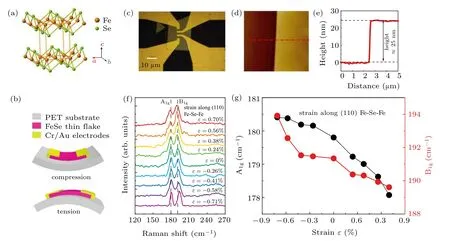
Fig.1.Crystal structure,device configuration and strain-dependent Raman spectra of FeSe.(a)The crystal structure of the pristine FeSe.(b)Schematic structure of a FeSe thin flake on the flexible polyethylene terephthalate(PET)substrate.Variable compressive/tensile strains are induced on FeSe thin flakes by bending the substrate downward/upward.(c)An optical image of a FeSe thin flake supported on flexible PET substrate.(d),(e)AFM image of the dashed square in(c).The thickness of FeSe thin flake is about 25 nm along the red dashed line.(f)In-situ Raman spectroscopy of the FeSe thin flakes under different tensile and compressive strains with the strain along(110).The peaks of A1g and B1g modes move to the lower wave number with increasing the tensile strain and shift to the higher wave number with increasing the compressive strain.(g)The peak positions of A1g and B1g modes as a function of the strain.The frequencies of the A1g and B1g modes monotonously decrease with increasing the strain from negative to positive.
As shown in Fig.1(a),due to the van der Waals interaction between different FeSe layers,the FeSe thin flakes can be easily obtained by the mechanical exfoliation with scotch tape method.FeSe thin flakes are first mechanically exfoliated from bulk crystals onto polydimethylsiloxane(PDMS)substrates,and then transferred to PET substrates by the so-called dry-transfer method.[38](see supplementary materials for the details of devices fabrication).Figure 1(b)is the schematic structure of the final strain device.In practical,proper thin flakes with good flatness and regular shape are chosen by using an optical microscopy.Then,the thickness is characterized by an atomic force microscopy(AFM).The typical thickness of the FeSe thin flakes used for the transport measurement is about 25 nm as evidenced by the AFM image as shown in Figs.1(d)and 1(e).Finally,four electrodes(Cr/Au with thicknesses of 5 and 50 nm,respectively)for transport measurements are coated on the surface of the FeSe thin flakes by using mask technique.The coated four electrodes also serve as the clamping points to prevent the sample from slippage during the bending of the substrate.Figure 1(c)displays an optical image of the actual device.It should be noted that the inplane crystal orientation of FeSe single crystal is determined by Laue diffraction measurement.The applied strain by bending the PET substrate is always along the[110]or[100]direction.The direction of the current can be changed by varying the direction of the electrodes.
The strain induced by bending the PET substrate can be estimated by a continuum-mechanics model for an elastic beam(see supplementary material S2),in which the radius of curvature(R)from the bending of the PET substrate is assumed to be much larger than the thickness(h)of the PET substrate.Then,the magnitude of the applied strain can be calculated byε=h/2R[39](see details in Fig.S1 of the supplementary materials).A positive/negativeεdenotes a tensile/compressive strain,respectively.In this work,the thickness of the PET substrate is about 100µm,and we could extract the value of R from the profile of the bended PET substrate.In order to continuously change the strain in the FeSe thin flakes,the prepared device is fixed in the middle of two parallel plates and the distance between these two plates is continuously changed to bend the PET substrate.If no slippage happens between the FeSe thin flake and PET substrate,then the strainεin the FeSe thin flake can be directly calculated by the above formula.Here,the sample should be mounted in the middle position of the substrate.

Fig.2.The longitudinal resistance and the temperature derivatives of the resistance at differentεalong(110).(a),(d),(g)and(j)Temperature dependence of resistance for FeSe thin flakes under different strains and different current directions.The inset is a schematic of the strain and the direction of the measured current.(b),(e),(h)and(k)The resistance at low temperatures corresponding to(a),(d),(g)and(j).(c),(f),(i)and(l)Temperature dependence of the temperature derivative of resistance for the samples corresponding to(a),(d),(g)and(j).
Usually,x-ray diffraction(XRD)experiment is needed to verify the change of lattice parameters due to uniaxial strain.However,due to limited sample’s volume,it is very difficult to perform an in-situ XRD measurement on the FeSe thin flakes as that in large single crystal.[40]Instead,we have performed in-situ Raman measurements,which is sensitive to uniaxial strains on the FeSe thin-flake samples.As shown in Fig.1(f),we successfully obtain in-situ Raman spectra for the FeSe thin flakes under various strains along[110]direction.The A1gand B1gmodes come from the vibrations of Se atoms along the c axis and the vibrations of Fe atoms along the c axis,respectively.[41–43]By increasing the strain from tensile to compressive strain,both A1gand B1gmodes continuously shift to a higher wavenumber.The systematic evolution of A1gand B1gmodes with the uniaxial strain is shown in Fig.1(g).Qualitatively,although the absolute magnitude of the uniaxial strain on the FeSe thin flakes can not be determined precisely,the in-situ Raman result indicates that the uniaxial strain by bending the PET substrate is effectively transferred to the FeSe thin flakes.Similar in-situ Raman results are also obtained in the FeSe thin flakes under various strains along[100]direction(see supplementary materials Fig.S3).Therefore,we assume that the calculated value of strain by the above mentioned method well represents the actual strain in the FeSe thin flakes.Next,we would investigate the strain effects on both superconducting and nematic transitions in the FeSe thin flakes by electronic transport measurements.
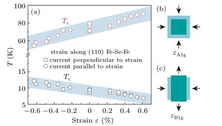
As shown in Fig.2,the temperature dependence of resistance for the FeSe thin flakes are systematically measured under different strains along the[110](Fe–Se–Fe)direction.In order to measure both tensile/compressive strain effects with the electric current parallel or perpendicular to the bending direction,we have prepared four similar strain devices to measure the temperature-dependent resistance.Figures 2(a)and 2(d)show the temperature dependences of resistances under tensile strain,with the electric current parallel and perpendicular to the direction of the uniaxial strain,respectively.The overall temperature dependence of resistance is very similar to the previous report on the bulk FeSe,[18]excepting a higher superconducting temperature and a lower nematic transition temperature.Such difference in superconducting and nematic temperatures between bulk FeSe and FeSe thin flake has already been reported in previous study.[44]Moreover,with increasing the tensile strain,the temperature-dependent resistances show a clear difference below the nematic transition temperature with current parallel and perpendicular to[110]direction,which suggests that the FeSe thin flake on the PET substrate is detwinned with the applied tensile substrate.The superconducting temperature(defined as the middle point of the resistive transition Tmidc)drops from the initial 9 K to 7.8 K with a tensile strain up to 0.47%in the device,when the electric current flows perpendicular to the direction of uniaxial strain.In the device with the electric current parallel to the direction of uniaxial strain,Tmidc drops from the initial 9.6 K to 6.9 K with a tensile strain up to 0.61%.In spite of slightly difference between different devices,it is clear that the superconducting temperature is almost linearly suppressed by increasing the tensile strain along the[110]direction.On the other hand,the nematic transition temperature(Ts)is determined from the derivative of the temperature-dependent resistance.As shown in Figs.2(c)and 2(f),there is a clear sharp jump due to the nematic transition in the differential curves.Tsis determined by the minimum of the jump.In the device with current parallel to the direction of uniaxial strain,Tsgradually increases from initial 71.2 K to 91.2 K with a tensile strain up to 0.61%.In the device with current perpendicular to the direction of uniaxial strain,Tsgradually increases from initial 70.4 K to 83 K with a tensile strain up to 0.47%.Therefore,in contrast to the superconducting temperature,the nematic transition temperature is clearly increased as the tensile strain increases.

Fig.3.(a)Tc and Ts as a function of the strainεwhen the strain is applied along the[110]direction.With increasing the tensile strain,Tc gradually decreases and Ts gradually increases.With increasing the compressive strain,Tc gradually increases and Ts gradually decreases.There is a negative correlation between Tc and Ts.(b)and(c)Schematics of different strain types.εA1g is symmetry-preserving strain andεB1g is the strain component which breaks the four-fold rotational symmetry.

In general,a uniaxial stress applied along one in-plane direction(a or b axis)will induce strains along all three principal axes.[28]Then we haveεjj=−vijεii,where vijis the intrinsic Poisson ratio for materials.This gives

whereεA1g1andεA1g2are the non-symmetry-breaking strain such as volume expansion and change of tetragonality;and εB1gis the strain component which breaks the four-fold rotational symmetry.Based on symmetry considerations,Tcshould depend quadratically onεB2gbut linearly onεA1g.Accordingly,we have[28]

whereαandβare the dimensionless coefficients of the dependence of TconεA1gandεB1g,respectively.In the previous study on the underdoped Ba(Fe1−xCox)2As2,the straindependent Tcis found to be dominant by aεB1gcomponent and shows a quadratical dependence.In that case,the coefficient of the quadratic termαis believed to be related to the longrange antiferromagnetic order existing in Ba(Fe1−xCox)2As2andεB1gwould enhance spin fluctuations while suppress nematic fluctuations.[45]With increasing the amount of Co doping to the overdoped region,the antiferromagnetic order in Ba(Fe1−xCox)2As2is gradually suppressed and thenεA1gbecomes dominant on the strain dependence of Tc.Following this explanation on strain-dependent Tc,the absence of longrange antiferromagnetic order in bulk FeSe would lead to a negligible value ofαand then only a linear term would be left.This is definitely confirmed by the observation in the present study.Therefore,our results indirectly support a role of stripe-type spin fluctuations on superconductivity.In addition,as reported in previous literatures,Tcis found to be very sensitive to the change of the c-axis lattice constant in FeSe thin films,[27]which might be responsible for the observed predominant A1g-type strain effect.In fact,the A1gtype strain effect could be also compared with the pressure effect in FeSe,in which the superconducting transition temperature would be enhanced by low pressure below 1 GPa while the nematic transition temperature is suppressed.However,with further increasing pressure,a long-range antiferromagnetic order would appear and then Tcwould be slightly suppressed by the development of antiferromagnetic order.[46]Here,whether a long-range antiferromagnetic order would appear or not with further increasing strain is still elusive.It may deserve further study to clarify the underlying physics for the A1g-type strain effect.On the other hand,a similar B1g-type strain effect on the nematic transition temperature was also revealed in the underdoped Ba(Fe1−xCox)2As2.[28]However,our results clearly demonstrate that such a B1g-type strain effect on Tsis absent in FeSe.If assuming a key role of spin degree of freedom on the electronic nematicity in iron-pnictides,the absence of B1g-type strain effect on Tssuggests that the orbital degree of freedom might play a key role instead of the spin degree of freedom to drive the electronic nematicity.Since the orbital order is sensitive to the change of lattice parameter,[47–49]the dominant A1g-type strain effect on Tscould be also related to the change of lattice parameter induce by uniaxial strain as that for Tc.Therefore,combining the strain effect in both FeSe and Ba(Fe1−xCox)2As,the stripe-type spin fluctuations,which would lead to a B1g-type strain effect on both Tcand Ts,play a more important role than orbital fluctuations on the superconductivity in IBSCs.In fact,this is also supported by a slight change of Tcacross the nematic quantum critical point in FeSe1−xSxsystem.[25]Recently,several experiments on the strain-tuning effects of bulk FeSe have been conducted by different groups.[35–37]Owing to different measuring methods and sample dimensions,there is a few slight differences in the detailed behavior of Ts(ε)and Tc(ε)among different experiments.[35–37]Nevertheless,consistent conclusions are obtained,which suggest intrinsic strain-tuning effects revealed in this study.
In summary,by utilizing PET substrate,we successfully obtain a wide-range strain tuning for FeSe thin flake with both tensile and compressive strain up to about 0.7%.Our results reveal a predominant A1g-type strain effect on Tc,which is different from that of B1g-type in underdoped Ba(Fe1−xCox)2As2.Meanwhile,Tsexhibits a monotonic anticorrelation with Tcand the maximum Tcreaches to 12 K when Tsis strongly suppressed under the maximum compressive strain.Finally,in comparison with the results in the underdoped Ba(Fe1−xCox)2As2,the absence of B1g-type strain effect in FeSe further supports a role of stripe-type spin fluctuations on superconductivity.Our findings provide new insights for clarifying the underlying mechanism of nematic order and its twist with superconductivity in iron-based superconductors.
- Chinese Physics B的其它文章
- Origin of anomalous enhancement of the absorption coefficient in a PN junction∗
- Protection of isolated and active regions in AlGaN/GaN HEMTs using selective laser annealing∗
- First-principles study of plasmons in doped graphene nanostructures∗
- Probing thermal properties of vanadium dioxide thin films by time-domain thermoreflectance without metal film∗
- An improved model of damage depth of shock-melted metal in microspall under triangular wave loading∗
- Signal-to-noise ratio of Raman signal measured by multichannel detectors∗

