Fundamentals and Processes of Fluid Pressure Forming Technology for Complex Thin-Walled Components
Shijian Yuan
aInstitute of High PressureFluidForming Technology,Harbin Institute ofTechnology,Harbin150001,China
b Institute of Precision Forming forHigh Performance,Dalian University ofTechnology,Dalian116024,China
Keywords:
ABSTRACT A new generation of fluid pressure forming technology has been developed for the three typical structures of tubes,sheets,and shells,and hard-to-deform material components that are urgently needed for aerospace,aircraft,automobile,and high-speed train industries.In this paper,an overall review is introduced on the state of the art in fundamentals and processes for lower-pressure hydroforming of tubular components,double-sided pressure hydroforming of sheet components,die-less hydroforming of ellipsoidal shells,and dual hardening hot medium forming of hard-to-deform materials.Particular attention is paid to deformation behavior,stress state adjustment,defect prevention,and typical applications.In addition,future development directions of fluid pressure forming technology are discussed,including hyper lower-loading forming for ultra-large non-uniform components,precision forming for intermetallic compound and high-entropy alloy components,intelligent process and equipment,and precise finite element simulation of inhomogeneous and strong anisotropic thin shells.
1.Introduction
Complex thin-walled components with curved contours are important for structures used in transportation equipment,such as rockets,aircraft,automobiles,and high-speed trains[1–3].These components are critical and widely used,for example,they occupy more than 80% of space vehicles and 50% of aircraft and automobiles.With the increasing demand for lightweight materials,long life cycles,and high reliability for in-service performance of new generation transportation equipment,conventional multiple segment structures fabricated by welding are not satisfactory and urgently require replacement by integrated components that are thin-walled and often contain complex curved contours[4].To successfully manufacture these kinds of components,the following three big challenges need to be addressed:①Shapes are extremely complex,comprising large dimensions with small features as well as having significantly varied curvature,irregular closed cross-sections,ultra-large overall size(the length of a tube or the diameter of a sheet is generally greater than 5 m),and ultra-thin thickness(the ratio of thickness to diameter is less than 3‰).These characteristics require deformation of raw material far beyond what is possible in conventional processes[5].②The preferred alloys for these components are hard to form.The formability of high-strength aluminium alloys[6,7],titanium alloys[8,9],intermetallic alloys[10],and nickel-based superalloys[11]is low at room temperature,while their microstructure and mechanical properties can deteriorate significantly at elevated temperatures.③Both high dimensional accuracy and good performance are cooperatively required for the components[12].Accuracy on the order of sub-millimetres(0.1–1 mm)or micrometres(1–100μm)is required throughout the components,and post-formed machining of their ultra-thin features is not practicable.Therefore,formed accuracy must be guaranteed by the forming directly.Moreover,properties of the thin-walled components(e.g.,ultimate strength)are required to obtain a 10%enhancement from the raw materials.These three challenges have to be dealt with cooperatively,resulting in huge manufacturing difficulties.Current forming technologies using rigid tools[13]are restricted by confined space,which is insufficient for large integrated components.Therefore,a compromised technical approach has to be used,whereby the component is fabricated by joining smaller formed pieces.Significant disadvantages arise in using this approach,including long welding seams consisting of alloys with reduced mechanical properties,shape distortion,surface degradation,reduced reliability,and short life cycles.These result in components that do not have the qualities required for next generation transportation equipment[14].
Fluid pressure forming is a metal forming technology in which a fluid medium is used to load and deform a workpiece,enabling a simple piece of blank material to be formed into a complexshaped integrated component.Pressurised fluid can replace some conventionally rigid tools to deform hard metals and exert loading within a closed space.In addition,fluid media are able to apply uniform pressure across the entire area of the deforming workpiece.These two unique advantages of fluid pressure forming make this a robust technology,which is being used for the manufacture of integrated complex-shaped components from simply shaped blanks in one operation[15].In the middle of the 1990s,driven by the demand for reducing the weight of automobile structures,the tube hydroforming process,also called internal high pressure forming in which pressures as high as 400 MPa are used,was developed[16].Research has been carried out on deformation behavior,defect mechanisms,and core processes for this hydroforming process by research institutes in Germany and United States[17,18].In particular,German companies successfully developed large-capacity tube hydroforming equipment,enabling mass production of chassis and body structures of passenger cars[19].Japanese researchers pioneered research into sheet hydroforming and successfully produced automobile panel components[20].
In 1998,a research group lead by the author started to study fluid pressure forming including both its fundamental theory and critical practical processes.The research strategy has been intended to overcome challenges in manufacturing integrated thin-walled components with complex curved contours.The research outcomes have been used to significantly develop and promote the use of fluid pressure for forming parts with a variety of geometrical complexities and dimensions(small to large)at different temperatures(cold to hot).Focusing on forming tubes,sheets,shells,and hard-to-deform materials,a new generation of fluid pressure forming technology has been successfully established,including lower-pressure hydroforming of tubular components,double-sided pressure hydroforming of sheet components,die-less hydroforming of ellipsoidal shells,and dual hardening hot medium pressure forming of hard-to-deform materials.In this article,state of the art relating to process principles,stress state adjustment,defect prevention,and typical practical product applications is discussed.
2.Process system and the principle of stress adjustment
2.1.The principle of forming process system
To produce a variety of structural features and materials required by different industrial sectors,end open structures with varied cross-sections,semi-closed structures with deep cavity,closed shells,and components of hard-to-deform materials have been developed using a range of fluid pressure forming processes with associated equipment after 30 years of research and development[21],as illustrated in Fig.1.For forming at room temperature,the fluid medium can be either water or oil,and this process is denoted as hydroforming.The medium used at elevated temperatures is either gas or solid granule.According to the specific structural characteristics of target components,either a tube or a sheet is used as the blank[22].
2.2.The principle of stress state adjustment
The unique characteristics of components that make the components difficult to be formed are large,thin-walled,closed cross-sections,and integral.Coupling these features with complex geometry and hard-to-deform materials(Fig.1)results in a high tendency for defects to occur such as wrinkling,splitting,and localized thinning.To overcome these difficulties,the principle of adjusting stress states in the deforming regions utilizing fluid medium loading is adopted to avoid specific defects.Essentially,by controlling the loading scheme of the fluid medium and the shape of the deformation zone,stress states can be kept within values enabling defects to be avoided[23,24],as shown in Fig.2[24].For instance,to overcome splitting,the stress state is altered from biaxial tension to tension–compression.To suppress wrinkling,an opposite stress adjustment is preferably used.Details of practical cases for adjusting stress-states considering the forming processes of typical tube,sheet,and shell structures are described in the following sections.
3.Lower-pressure hydroforming of tubular components having irregular profiles
Irregularly profiled tubular components are ideal parts for use in lightweight high-performance structures.Hydroforming tubular blanks enables conventional multi-part welded structures to be replaced by integrated structures of higher quality.Controlled by both the pressure inside a tube blank and the axial loading,the tube is gradually deformed radially and axially until it contacts the die cavity,producing an open-ended component with axially varied cross-sections.Due to the calibration of the small corner and hardening of the deformed material,an ultra-large force is raised by high pressure of up to 400 MPa.The resulted stress–strain field is likely to induce defects in the deforming tube,such as localized necking,wrinkling,and uneven thickness.Therefore,reducing forming pressure has always been a global approach to eliminate these defects.
The ultimate hydroforming pressure is inversely proportional to the corner radius of the transition zone.According to the empirical equation in Ref.[25],to form a component with a relative corner radius r/t(r is the corner radius,and t is the tube thickness)smaller than three,the forming pressure for the steel tube with a 450 MPa yield strength is higher than 150 MPa.However,due to the workpiece/tool interfacial friction,localized deformation and thinning usually occurs at transition zone corners,which can result in splitting.For the case of forming a square tubular section with small corner radii,instead of using a circular tube as a conventional workpiece,a square tubular workpiece with dished sides can be used to reduce the forming pressure,in which the tensile stress is basically reduced.These concave sides reduce the workpiece/die contact.Therefore,friction during deformation and the additional force provided by the flattened material under internal pressure enable the die corners to be filled without stretching of the workpiece,as shown in Fig.3[26].As internal pressure is applied,deformation of the sides moving towards the die walls is compressive and overcomes the reduced friction force.The stress state of the tube blank in the hoop direction is altered from tension to compression.As shown in Fig.2[24],the stress state is regulated from biaxial tension to tension–compression enabling the deformation limit to be increased.In addition,the decreased contact area with the die surface eases flow of material towards the corner zone,resulting in a significant reduction in the required forming pressure[26].Experiments have shown a 50%–80% reduction in the required ultimate pressure using the concave shaped preform compared to that of directly hydroforming a circular tube,as shown in Fig.4.Additionally,the thickness uniformity(i.e.,reduction of thinning rate)was more than doubled.
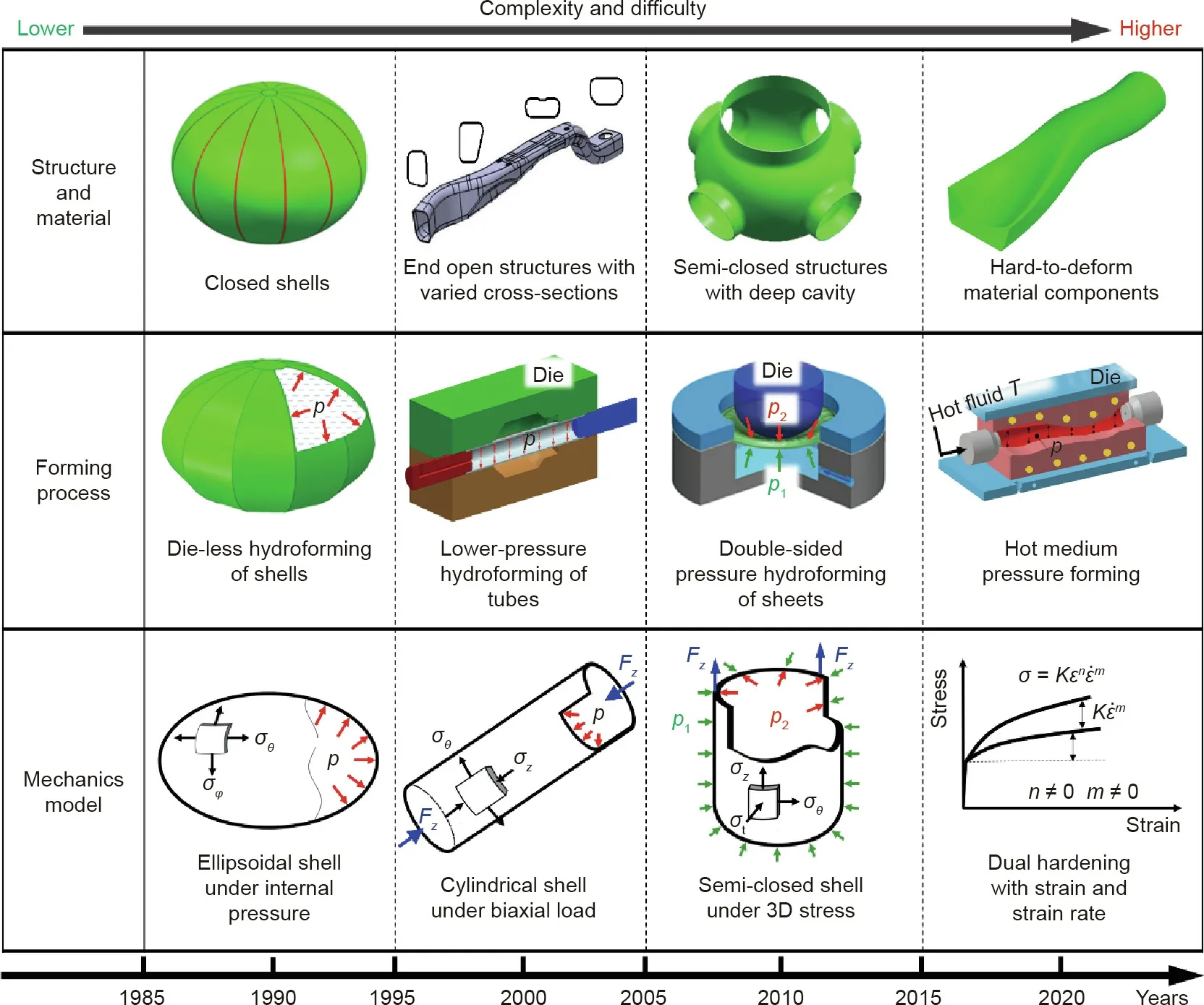
Fig.1.Component shape,process,and stress state.3D:three-dimensional;p:fluid pressure;p1:fluid pressure on the lower side of the sheet;p2:fluid pressure on the upper side of the sheet;T:forming temperature;σθ:hoop stress;σz:axial stress;σt:normal stress;σφ:longitudinal stress;Fz:axial force;σ:flow stress;ε:strain;˙ε:strain rate;K:strength coefficient;n:strain hardening exponent;m:strain rate hardening exponent.
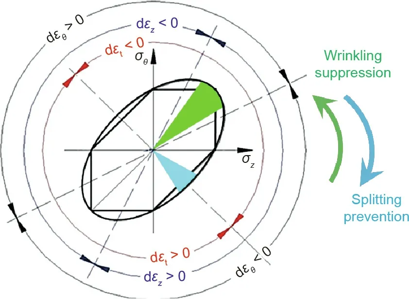
Fig.2.Principle of adjusting stress states.dεθ,dεz,and dεt are the strain increment in the hoop,axial,and normal directions,respectively.Reproduced from Ref.[24]with permission of Elsevier,©2006.
Numerical simulation is a robust tool to predict defects during tube hydroforming,while two typical challenges need to be addressed first.In addition to the above complete stress states experienced by the deforming material,macroscopic mechanical properties of tubes are often anisotropic due to the texture orientation of the microstructure arising during their fabrication,usually by extrusion,rolling,or drawing.Therefore,the precise determination of anisotropic parameters for thickness and yield strength and using them to establish reasonable anisotropic constitutive relationships and material models applicable for complete stress states,are vital to the prediction of deformation and defects using finite element simulation.Currently,to determine the coefficients in constitutive equations,the commonly used anisotropic constitutive relationships require the r value for thickness and the yield strengthσs,in at least three directions,(r0,r45,r90)and(σs0,σs45,σs90)[27].For sheets,anisotropic parameters in an arbitrary direction can be determined using uniaxial tensile specimens cut from any chosen orientation in the sheet,as shown in Fig.5(a)[28].While for tubes,tensile specimens can be extracted from tubes oriented only along its axis,as shown in Fig.5(b)[28].For specimens taken from the hoop direction(90°),the current commonly used hoop tensile test incurs friction and an additional bending deformation issue,resulting in a relatively large measurement error[29].The mechanical properties of tubes in any direction cannot be precisely obtained to date.
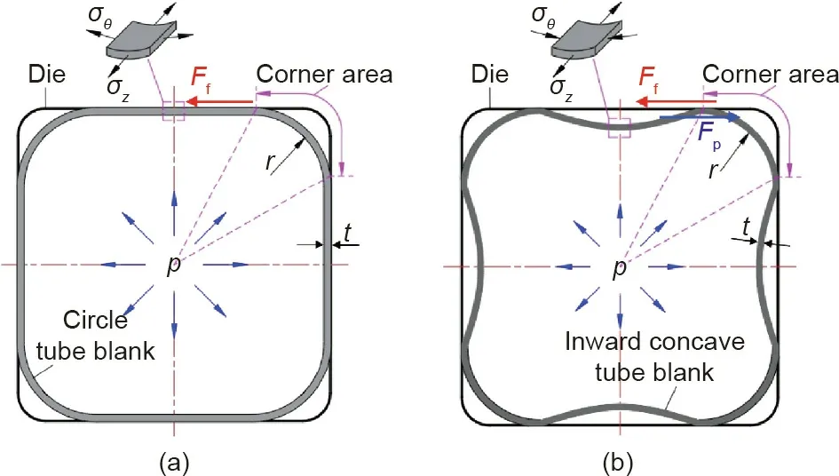
Fig.3.Principle of reducing the forming pressure.(a)Stress analysis in direct hydroforming using circle tube;(b)stress analysis on inward concave tube.Ff is the friction force sustained by the straight wall of tube during the calibration stage,Fp is the resulted tangential pushing force using the inward concave tube.Reproduced from Ref.[26]with permission of Journal of Aeronautical Materials,©2006.
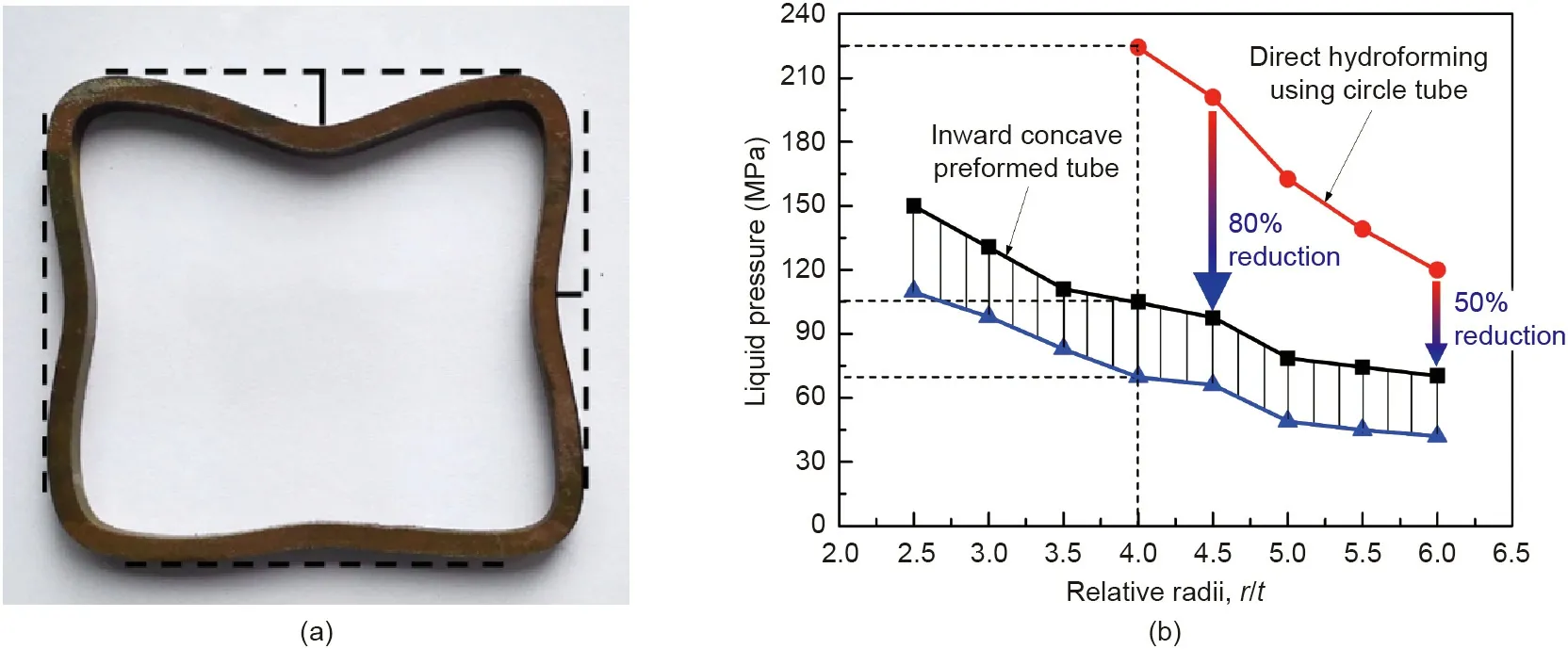
Fig.4.Effect of preform shape on forming pressure.(a)Concave shaped preform;(b)forming pressure.

Fig.5.Schematic of the uniaxial tensile test specimens located in different orientations of(a)sheet and(b)tube.Reproduced from Ref.[28]with permission of Journal of Plasticity Engineering,©2018.
To address this problem,theory and methodology to precisely determine anisotropic parameters of tubes in arbitrary directions have been proposed[30].A novel bulge test with controllable loading of inner pressure and axial load was developed successfully,which has been utilized to construct accurate plastic constitutive models of anisotropic thin-walled tubes under complex loading conditions[31],f(σz,σθ,σzθ,k).These models,as given in Eqs.(1)and(2),enable accurate simulations of non-symmetrical wrinkling and complex deformation of tubes with anisotropic properties.As shown in Fig.6,both the number and contour of the wrinkles have been excellently predicted.Three dominant wrinkles are generated with the middle one inclined to the axial direction and the wrinkles at two sides folded.


whereσzandσθare the axial and hoop stresses,respectively;σzθis the shear stress component;k is the anisotropic coefficient matrix of yield criterion;βrepresents the inclined angle with tube axis;dεzand dεθare the strain increment in the axial and hoop directions,respectively;dεzθis the shear strain increment;andσβand rβare the yield stress and normal anisotropy coefficient of tube,respectively,along any direction.
Fig.7 shows a chassis engine cradle for a passenger car,which was manufactured by the lower-pressure hydroforming method using a novel concave preform[32].The axis of this component is curved in three dimensions with more than ten complex irregular cross-sections.The ultimate tensile strength of material is 440 MPa.An approximate 250 MPa inner pressure is required using conventional direct hydroforming of the circular tube,while the pressure magnitude is significantly reduced to 120–130 MPa using the concave preform method.Since 2010,this innovative process has been used in mass production of this component.By the end of 2019,statistics show that 470 000 products have been produced with a defective index of 0.5%.

Fig.6.Simulation of non-symmetrical wrinkling phenomenon in thin-walled anisotropic tube.(a)Experimentation;(b)finite element method result.
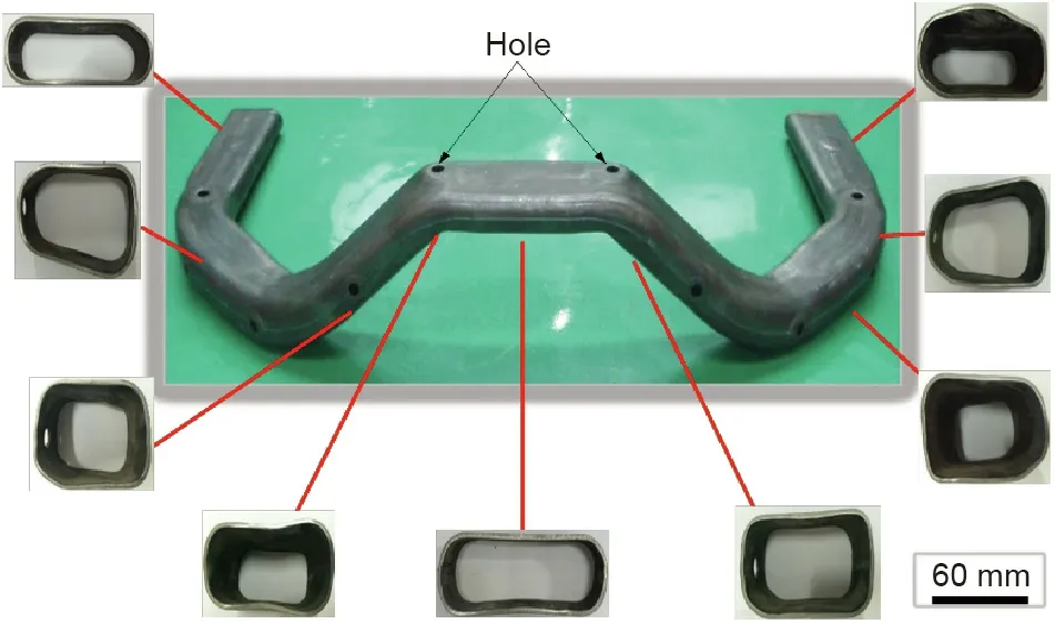
Fig.7.Hydroformed chassis engine cradle of a passenger car from First Automotive Works,China.
4.Double-sided pressure hydroforming of integrated sheet components
Formed sheets with curved contours are major structural components in rockets,aircraft,and aero engines.With the dramatically increasing demands for long life cycle and greater reliability,integrated components are urgently required to replace traditional multi-part welded components.The unique characteristics of these sheet-based components,which make them difficult to form in one piece,are summarized as follows:deep cavities(the ratio of depth to diameter of the cavity is greater than 0.5),ultra-slenderness(thickness),and semi-closed profiles.When the ratio of thickness to diameter is smaller than a limit value,wrinkling is very prone to occur,as the buckling resistance to compression is decreased.Refs.[33,34]have shown that,for low carbon steels,the critical ratio of thickness to diameter is approximately 5‰,while the low elastic modulus of aluminium alloy results in lower resistance to buckling,as shown in Fig.8.Therefore,its critical ratio of thickness to diameter is approximately 7‰.In addition,the semi-closed structures of many formed components offer high constraint to deformation,resulting in complex stress states that facilitate fracture.The co-existence of wrinkling and splitting during forming of semi-closed shell structures is a problem that conventional forming technology cannot overcome.
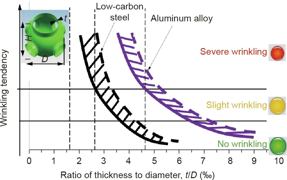
Fig.8.Correlation between wrinkling tendency and ratio of thickness to diameter for the semi-closed components with a deep cavity.D is the diameter,and H is the height of components.
The deformed zone in conventional deep drawing sustains a stress state of orthogonal tension and compression,in which,wrinkling is promoted by the compressive stress and splitting by the tensile stress.To address this problem,a double-sided pressure hydroforming process was proposed(Fig.9[35]).The liquid pressure is simultaneously applied on both the upper and lower sides of the sheet,and reverse bulging in the deforming zone is generated through suitable control of the liquid pressure.Then,the conventional tension–compression stress state is positively altered to a biaxial tension state.The avoidance of compressive stress enables the wrinkling tendency to be eliminated.In addition,through control of the liquid pressure exerted on the upper surface of sheet,the tensile stress can be regulated within a certain zone in the first quadrant of stress space,hence avoiding the occurrence of splitting.
Fig.10 shows a successfully formed integrated component with five branches,using double-sided hydroforming.The previous structure that was welded at the equator and four of the branches has a tendency to fracture.In comparison,as the integrated component has no welded seams,this tendency is avoided,and it conforms to thickness and dimensional accuracy specifications.
For the manufacture of large semi-closed components,a series of innovative techniques for hydroforming equipment have been developed.These developments have enabled realization and control at considerably large liquid volume flow rates at high pressure.The largest hydroforming equipment that has been successfully developed in the world is shown in Fig.11[36].It is bigger than the previous largest equipment made by Schuler in Germany.The contained pressurised liquid volume is 5 m3,and its force capacity is 150 MN,which are 5 times and 1.5 times that of the specifications of the Schuler equipment,respectively.Using this larger capacity equipment,a thin sheet with a similar thickness to the final component was used to form the integrated dome of a fuel tank using a single operation[36].The conventional component consisting of multiple welded segments has been replaced,enabling approximately 30 m welded seams to be eliminated,which effectively increases its reliability.Manufacturing lead time is reduced by 2/3.
5.Die-less hydroforming of large-size ellipsoidal shells

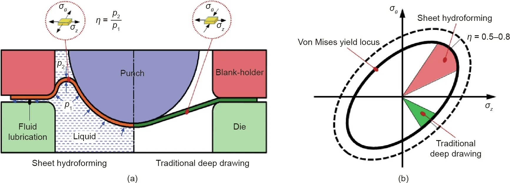
Fig.9.Principle and stress states of double-sided hydroforming of a sheet.(a)Forming principle,(b)stress states[35].ηis the ratio between the fluid pressure on the upper side of the sheet to the fluid pressure on the lower side of the sheet.
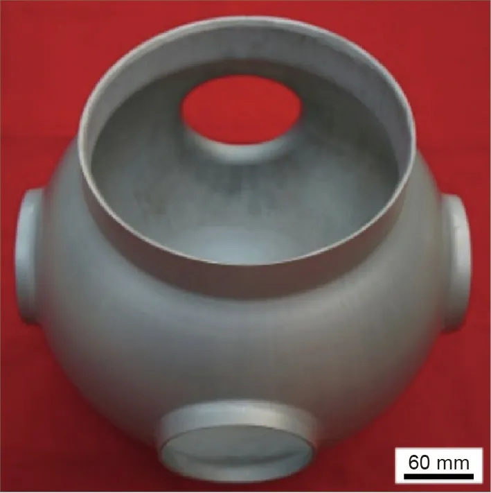
Fig.10.Integrated component with five branches.
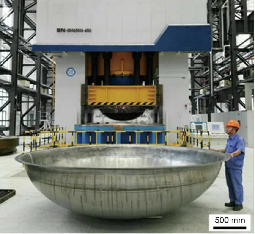
Fig.11.Ultra-large capacity hydroforming equipment and integrated dome component.Reproduced from Ref.[36]with permission of The Japan Society for Technology of Plasticity,©2018.
6.Dual hardening hot medium pressure forming for components of hard-to-deform materials
High-strength aluminium alloys(2000 series,7000 series,and aluminium–lithium alloy),titanium alloys,and nickel-based superalloys are common materials used for thin-walled integrated structures in space vehicles,high-speed trains,and environmentally friendly energy vehicles[42,43].These hard-to-deform alloys are often used for large components of complex shape with small features.Successful workpiece deformation using the current cold forming processes,including hydroforming,is achieved essentially by manipulation of the strain hardening characteristics,while significant deformation is achieved in high temperature superplastic forming using the strain rate hardening characteristic.Reliance on this single hardening property severely limits the degree of deformation that can be obtained before localized thinning arises;additionally,obtainable formed shape complexity is significantly restricted as a result[44].
It is known that alloys exhibit both strain and strain rate hardening when deformed in a middle temperature range of 0.3Tm–0.5Tm(Tmis the melting temperature of materials)and at a strain rate greater than 0.1 s-1[45–47].By elevating workpiece temperature and employing a suitable rate of deformation,both hardening mechanisms can be activated simultaneously(dual hardening)[48,49].Based on this premise,a novel hot medium pressure forming process,using combined strain and strain rate hardening,was developed[50].Micro-mechanisms and stress–strain relations for the three processes are shown in Fig.14.
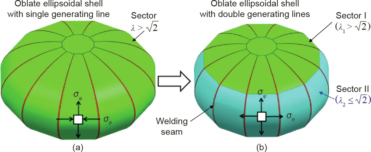
Fig.12.Stress states in die-less hydroforming of ellipsoidal structures using shell sectors with(a)single generating line and(b)double generating lines.Reproduced from Ref.[40]with permission of Elsevier,©2016.
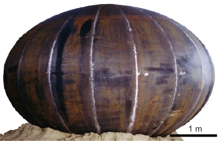
Fig.13.Industrial-scale ellipsoidal shell with axis length ratio of 1.5.
Based on the underlying physical internal variables[51],including dislocation mechanics,grain size,and viscoplastic constitutive relationships for hot medium pressure forming,decomposition methodology for the dual hardening was developed under complex stress states.This methodology enables the coupled dual hardening to be quantitatively characterised and accurate process simulations to be achieved[52].Through a series of biaxial loading experiments,a process window coordinated by regulating the pressure and temperature of hot medium pressure forming has been established for different alloys,which is shown in Fig.15.Such a process window can be used to optimize process parameters and loading paths to enable precision forming of integrated hard-to-deform alloys[53].This novel dual hardening hot medium pressure forming method has the potential to overcome the intrinsic limitation of processes utilizing only a single hardening characteristic of a workpiece.Fig.16[47]shows complex-shaped thinwalled components of an aluminium alloy and a titanium alloy formed by utilizing dual hardening mechanisms.For the aluminium alloy component,local small features,such as those of the convex logo,three-dimensional(3D)compound corners,and complex-shaped cross-sections(rectangular,circular,and petal shape),were successfully formed,and uniform thickness distribution of the petal shaped cross-section was obtained.For the titanium alloy component,the ratio of two diameters(D2/D1;D1and D2are the end diameters of the tubular component)is 2.15.The dimensional accuracy is within 0.18 mm of nominal.The ultimate tensile strength is 14.5% higher than that of the raw material.
7.Development directions and perspectives
Driven by the continuing goals of achieving lighter weight,greater reliability,and longer life cycle for future equipment used in aerospace vehicles,aircraft,new energy automobiles,and high-speed trains,the following aspects of fluid pressure forming technology need to be further developed.
(1)Hyper lower-pressure integral forming for ultra-large size components of combined materials.With the development of heavy rockets,large-scale aircraft,and new generation highspeed trains,thin-walled components with ultra-large dimensions(up to 10 m)are urgently required.However,due to the current size limitation of raw sheet blanks,tailored blanks with several welded seams have to be used,which introduces the problems to workpieces with inhomogeneous mechanical properties.The deformation of such non-uniform blanks is very complex,and splitting is more likely to occur near the welded seams.In addition,ultra-large workpieces require extremely high forming loads.For example,with regard to a semi-closed structure with a diameter of 5 m,the necessary forming load can be as high as 400 MN.The cost of equipment that is able to provide such high loads is extremely high.Future research is believed to be towards inventing the hyper lower-pressure hydroforming technology(more than 80%reduction of load)and developing equipment for forming ultralarge size components.
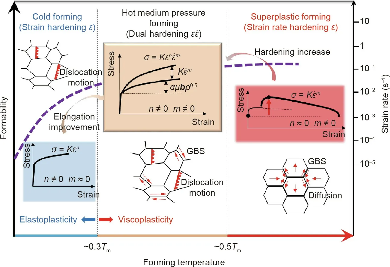
Fig.14.Micro-mechanisms and stress–strain relations within three temperature ranges.GBS:grain boundary sliding;μ:critical shear stress;α:material coefficient;b:Burger’s vector;ρ:dislocation density.
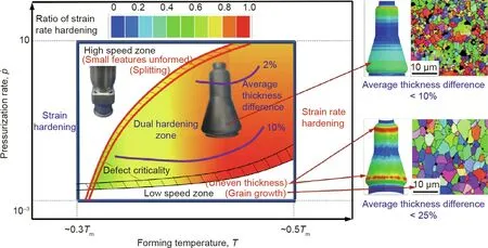
Fig.15.Process window of dual hardening hot medium pressure forming.
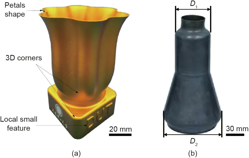
Fig.16.Complex-shaped components manufactured by hot medium pressure forming.(a)Aluminium alloy component;(b)titanium alloy component[47].
(2)Precision forming for components of intermetallic compounds and high-entropy alloys.Intermetallic compounds,such as titanium aluminium,nickel aluminium,and high-entropy alloys,are ideal lightweight heat-resistant materials to replace conventional nickel-based superalloys for high temperature service applications.However,the ductility of these alloys is extremely low(virtually zero at room temperature),while the limited size of raw materials is also an obvious limitation.Considering the complex chemical compositions and phase transformations characteristics of these materials,it is necessary to determine the effects of deformation conditions(temperature,strain,and strain rate)to enable fluid pressure forming technologies with novel features to be developed while achieving manufacture of practically useful components.
(3)Intelligent process and equipment of fluid pressure forming.To date,computer numerical control has been used for process and equipment control in fluid pressure forming.Precise digitalised closed-loop control enables process parameters such as pressure,displacement,and clamping force to be controlled following predesigned paths during the forming process.However,due to process inconsistencies,such as workpiece properties variation and tool wear,components outside specification are occasionally formed.By establishing a comprehensive and intelligent model based on underlying correlations between deformation behavior and process parameters,the occurrence of defects is able to be self-judged in-line during the forming,which facilitates equipment to adjust process parameters simultaneously.Such a framework of intelligent forming could considerably reduce the probability of defective components being produced.
(4)Deformation theory and precise simulation of inhomogeneous and strong anisotropic thin shells.During fluid pressure forming,the initial blank is normally preformed in one or two operations before the final forming operation.This can result in localized thinning or thickening and localized hardening in the blank,thus,the mechanical/physical properties of blanks are inhomogeneous.The entire deformation sequence from preforming to final forming is a multi-step process with cyclic loading and unloading,and current theory and models are unable to describe the deformation behavior of these materials.To enable accurate predictions of the processes and products to be made,entirely new yield equations,flow equations,constitutive models,and experimental test methods are required.
Acknowledgements
The investigations presented herein are financially supported by the National Science Fund for Distinguished Young Scholars(50525516)and the National Natural Science Foundation of China(U1637209,51175111,50375036,and 59975021).The author wishes to express his gratitude for the funding support.
The author would like to thank for great contributions of colleagues of the group,who are Professor Gang Liu,Professor Yongchao Xu,Professor Wei Liu,Dr.Xiaosong Wang,Dr.Cong Han,Dr.Xiaolei Cui,and Qibin Miao from Institute of High Pressure Fluid Forming Technology,Harbin Institute of Technology,and Professor Zhubin He,Dr.Yanli Lin,Dr.Xiaobo Fan,and Dr.Kailun Zheng from Institute of Precision Forming for High Performance,Dalian University of Technology.In addition,sincere thanks are given to Professor Trevor A.Dean on the useful comments and help on proof reading.
- Engineering的其它文章
- Evaluation Method and Mitigation Strategies for Shrinkage Cracking of Modern Concrete
- Progress in Research and Development of Molten Chloride Salt Technology for Next Generation Concentrated Solar Power Plants
- One-Step Preparation of Green Fabric for Continuous Antibacterial Applications
- Process Intensification in Pneumatically Agitated Slurry Reactors
- Extreme Learning Machine-Based Thermal Model for Lithium-Ion Batteries of Electric Vehicles under External Short Circuit
- New Standards Release Sets Stage for 5G Future

