Progress in Research and Development of Molten Chloride Salt Technology for Next Generation Concentrated Solar Power Plants
Wenjin Ding*,Thomas Bauer
a Institute of Engineering Thermodynamics,German Aerospace Center(DLR),Stuttgart 70569,Germany
b Institute of Engineering Thermodynamics,German Aerospace Center(DLR),Cologne 51147,Germany
Keywords:
ABSTRACT Concentrated solar power(CSP)plants with thermal energy storage(TES)system are emerging as one kind of the most promising power plants in the future renewable energy system,since they can supply dispatchable and low-cost electricity with abundant but intermittent solar energy.In order to significantly reduce the levelized cost of electricity(LCOE)of the present commercial CSP plants,the next generation CSP technology with higher process temperature and energy efficiency is being developed.The TES system in the next generation CSP plants works with new TES materials at higher temperatures(>565°C)compared to that with the commercial nitrate salt mixtures.This paper reviews recent progress in research and development of the next generation CSP and TES technology.Emphasis is given on the advanced TES technology based on molten chloride salt mixtures such as MgCl2/NaCl/KCl which has similar thermo-physical properties as the commercial nitrate salt mixtures,higher thermal stability(>800°C),and lower costs(<0.35 USD∙kg-1).Recent progress in the selection/optimization of chloride salts,determination of molten chloride salt properties,and corrosion control of construction materials(e.g.,alloys)in molten chlorides is reviewed.
1.Introduction
Concentrated solar power(CSP)plants with thermal energy storage(TES)system are emerging as one kind of the most promising power plants in the future renewable energy system,since they can supply dispatchable and low-cost electricity with abundant but intermittent solar energy.As reported by Renewable Energy Policy Network for the 21st Century(REN21),more than 550 MW new commercial CSP plants began operation in 2018[1].Most of them include the TES system to generate dispatchable electricity.From 2008 to 2018,the global installed CSP-capacity increased significantly from~0.5 to~5.5 GW[1].SolarPACES(short for Solar Power and Chemical Energy Systems),which is an international cooperative network for the development and marketing of CSP systems,presents the status of all CSP projects around the world,either operational,under construction,or under development on its website(solarpaces.org/csp-technologies/csp-projects-aroundthe-world/).At the time of writing,most of CSP plants in operation(~5.8 GW in June 2019)are localized in Spain,the United States,Morocco,and South Africa,while Middle East and North Africa(MENA)and China are constructing most of the new CSP plants(~2.2 GW).Additionally,more than 1.5 GW CSP plants are under development mainly in Europa,Chile,South Africa,and Australia.
As illustrated in Fig.1,the CSP technologies include linear Fresnel reflector,central receiver(i.e.,power tower),parabolic dish/engine systems,and parabolic trough systems[2].Among them,linear Fresnel reflector and parabolic trough systems belong to linear focusing CSP systems,while power tower and parabolic dish/engine systems are point focusing.Compared to the linear focusing CSP systems,the point focusing ones can produce solar heat at higher temperatures owing to their higher sunlight concentration ratio.Thus,they can have higher energy efficiencies and lower levelized cost of electricity(LCOE).Most of the present CSP plants in operation use linear focusing parabolic trough technology due to its simplicity of construction and maintenance,whereas most of the CSP plants under construction are power tower systems[2].

Fig.1.Four types of CSP technologies[2].
The first generation CSP plants such as the parabolic trough solar electric generating system I(SEGS-I)in the United States did not integrate a TES system and therefore cannot produce dispatchable electricity.In order to increase the competitiveness compared to the conventional power plants and other renewable energy technologies,TES systems using,for example,molten nitrate salts at low temperatures(293–393°C;e.g.,Andasol 1 parabolic though CSP plant in Spain)and high temperatures(290–565°C;e.g.,Gemasolar power tower CSP plant in Spain,Crescent Dunes power tower CSP plant in the United States)are integrated into the CSP plants in the second generation to generate dispatchable electricity and reduce LCOE.The power tower systems with operation temperatures up to 565°C do have higher energy efficiencies of the power cycle compared to the parabolic trough systems with operation temperatures up to~400°C.
The TES technologies can be classified as sensible TES using liquid or solid materials,latent TES using phase change materials,and thermochemical TES using reversible chemical reactive materials[3].The state-of-the-art commercial molten nitrate salt technology is a sensible TES technology.For more information about the TES technologies for CSPs,either commercialized or in development,a current comprehensive review[3]is suggested.
Fig.2 illustrates a typical second generation CSP plant—a stateof-the-art commercial power tower CSP plant with a direct molten nitrate salt TES system[4].Such a CSP plant consists of four main parts—heliostats,a receiver tower,a molten salt TES system,and a power generation system.The sunlight is reflected by the heliostats to the central receiver on the top of the tower and transformed to heat by the absorber on the receiver.The absorbed heat is transferred and stored in a heat transfer fluid(HTF)and TES material(i.e.,molten salt),and can be used to generate the electricity by a conventional steam Rankine power cycle.The inexpensive storage of the solar heat in the TES material allows CSPs to generate dispatchable low-cost renewable electricity during the absence of sunlight.The common commercial molten salt TES material is a non-eutectic salt mixture of NaNO3/KNO3(60 wt%/40 wt%),commonly known as Solar Salt.Fig.3 shows the two-tank molten salt TES system of the Andasol 3 50 MW CSP plant in Spain,which contains~28 500 metric tons Solar Salt for 7.5 h storage[5].The heat storage capacity Q of a molten salt TES system can be defined with the temperature difference of the hot and cold tankΔT,as well as the mass m and specific heat capacity cpof the molten salt:

However,the molten nitrate salt mixtures used in the second generation CSP plants have a limited maximum operation temperature of around 565°C(limitedΔT and Q)due to thermal decomposition[6].More about current progress in research and development(R&D)of molten nitrate salt TES technologies with different mixtures can be found in a review paper[7].
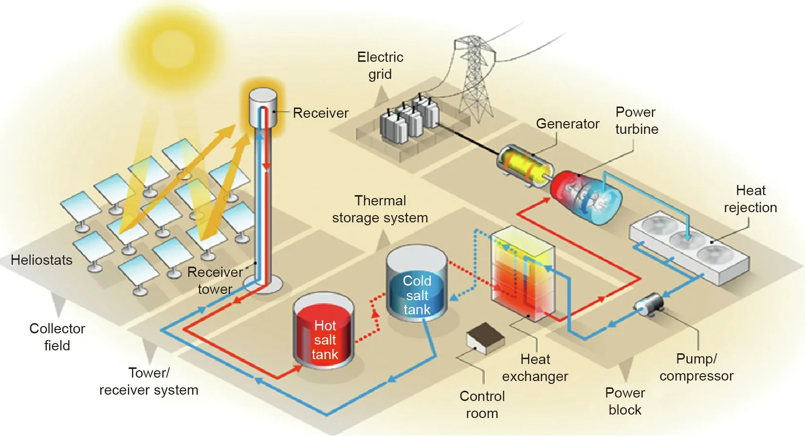
Fig.2.A state-of-the-art power tower second generation CSP plant with molten nitrate salts as TES/HTF materials[4].HTF:heat transfer fluid.
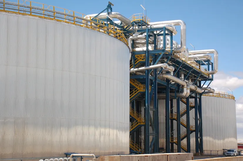
Fig.3.Two-tank molten salt TES system of Andasol 3 50 MW CSP plant in Spain.Storage capacity:~28 500 metric tons Solar Salt for 7.5 h storage.Source:Andasol 3.
In 2017,National Renewable Energy Laboratory(NREL)in the United States proposed the demonstration roadmap of the next generation CSP technology(Third Generation CSP,Gen3 CSP)with higher operation TES/HTF temperatures(maximum operation temperature>700°C)[4].In 2012,the Australian Renewable Energy Agency(ARENA)started supporting the R&D of advanced CSP technologies within the framework of Australian Solar Thermal Research Initiative(ASTRI)[8].In these ongoing research programs,much effort has been or is being given on development of the next generation TES technologies for the next generation CSP technology.Compared to the present molten nitrate salt technology,they are expected to have higher operation temperatures and lower capital expenditures(CAPEXs).The promising TES technologies include molten salt technology using salts with higher thermal stability such as chlorides and carbonates[4,9,10],salts-based phase change material(PCM)technology[3,11],and solid particle technology,for example,using sintered bauxite particles[3,4].Among these TES technologies,the molten salt technology using salts with higher thermal stability represents the most familiar approach,and is considered to be one of the most promising TES technologies for the next generation CSP technology,since this approach would not significantly change from the state-of-theart CSP power tower design as shown in Fig.2[12].
Fig.4 shows the schematic of one of the next generation CSP concepts proposed by NREL:a novel molten salt TES/HTF system(operation temperature range of 520–720°C)combined with a supercritical carbon dioxide(sCO2)Brayton power cycle(operation temperature range of 500–700°C)[4].Compared to the conventional steam power cycle with a thermal to electrical energy efficiency of~40%,the sCO2Brayton power cycle can have a thermal to electrical energy efficiency higher than 50%[4].Thus,it has a great application potential in the next generation CSP and other power plants such as nuclear power plants[4].In the presented work,sCO2power cycles are not further discussed.For current status and progress of R&D in the sCO2power cycles integrated with CSP,a comprehensive review published recently[13]is suggested.
Molten chloride salts such as MgCl2/NaCl/KCl are one kind of the most promising TES/HTF materials in the next generation molten salt technology due to their excellent thermo-physical properties(e.g.,viscosity,thermal conductivity),high thermal stability(>800°C)and low costs(<0.35 USD∙kg-1)[14].Additionally,the development experience from the commercial molten nitrate salt technology can be used for overcoming the challenges in the development of this new molten salt technology[12].However,compared to the commercial molten nitrate salt technology,one of the main additional challenges is high corrosiveness of molten chlorides to the metallic construction materials(i.e.,alloys)at high temperatures[12,14].Thus,effective,efficient,and affordable corrosion control technologies are essential for this advanced technology.
This paper will review the recent progress in R&D of the next generation CSP technology in relation to advanced TES and HTF technologies over the world under research programs in Section 2.In Section 3,emphasis is given on the molten chloride salt technology.In this section,the recent progress in selection/optimization of chloride salts,determination of molten chloride salt properties,and corrosion control of construction materials(e.g.,alloys)in molten chlorides is reviewed.The last Section 4 summarizes the main progress in R&D of the next generation CSP and TES technologies,and gives some perspectives of future R&D topics for realizing their final application.
2.Next generation CSP technology
To develop the next generation CSP technology with higher energy efficiency and lower LCOE,different initiatives have been launched or R&D projects have been started by the countries/regions including the United States,Australia,Europe,and Asia in this decade.For instance,within the framework of the SunShot Initiative starting in 2011[15],the US Department of Energy(DOE)started to fund topics related to the aforementioned Gen3 CSP program in 2018.The ARENA started the ASTRI in 2012 to improve the current CSP technologies and develop the next generation CSP technology[16].Since 2004,the R&D of CSP technologies including the next generation CSP technology has been supported by European Union(EU)in the funding programs(e.g.,Framework Programs for Research and Technological Development(FP6 and FP7)and Horizon 2020(H2020))[12].Besides the R&D projects,some EU networking projects including the Solar Facilities for the European Research Area(SFERA)I–III projects[17–19]and Scientific and Technological Alliance for Guaranteeing the European Excellence in Concentrating Solar Thermal Energy(STAGE-STE)project[20]are funded.Additionally,other countries like China have started some prior studies for the next generation CSP technology,for example,on the next generation TES technology with molten chloride and carbonate salts since 2011[21–23].Currently,the Ministry of Science and Technology(MOST)of the People’s Republic of China started the national research project—‘‘Supercritical CO2Solar Thermal Power Generation”via the National Key R&D Program of China[24].
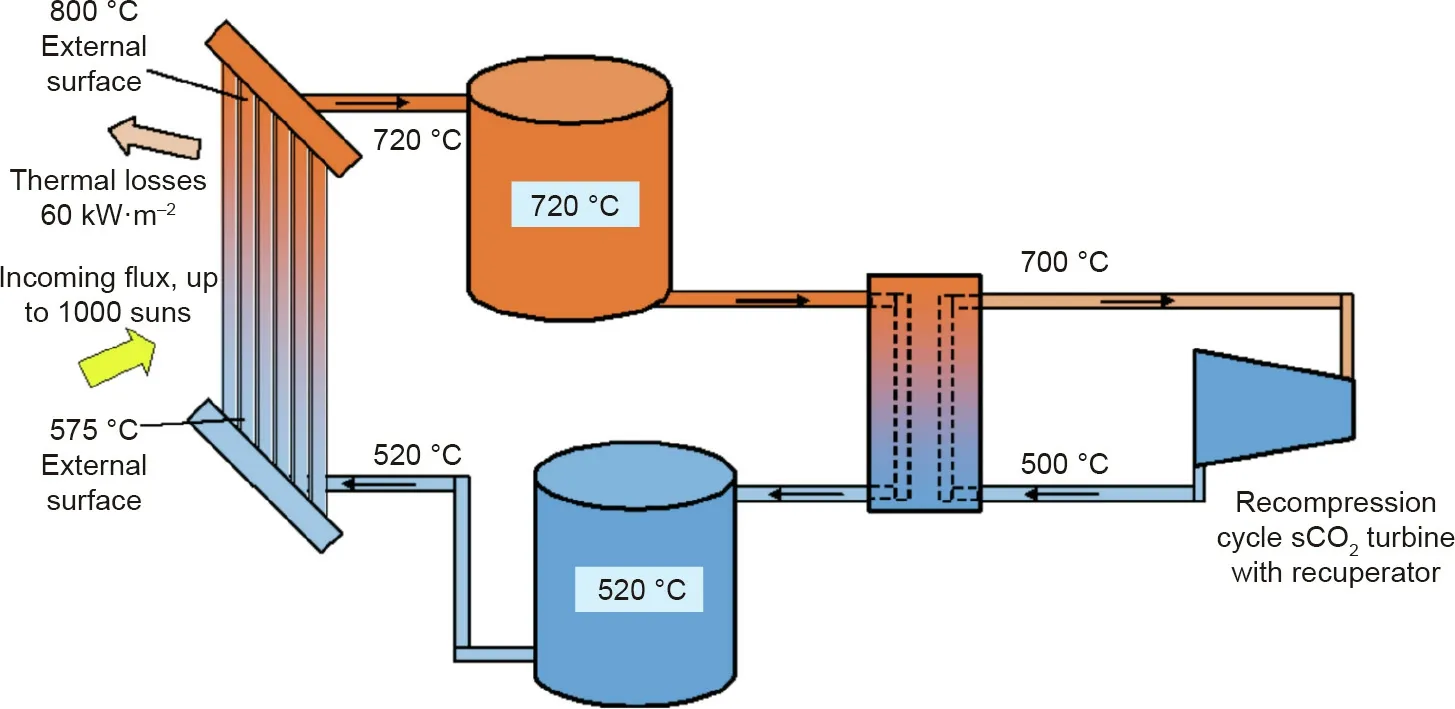
Fig.4.One of the next generation CSP concepts in the demonstration roadmap of Gen3 CSP[4]:next generation molten salt TES/HTF system integrated with sCO2 power cycle.1000 suns:sunlight concentration ratio achieved by power tower CSP technology.
The following subsections discuss recent progress in R&D of the next generation CSP technology in the United States,Australia,Europe,and Asia,as well as efforts by the International Renewable Energy Agency(IRENA)to support further CSP developments.The following discussion considers the next generation CSP and TES/HTF technologies as approaches to increase the operation temperature to a higher temperature level than current tower systems with nitrate salts up to 565°C.
2.1.The United States
In 2011,DOE launched the ten-year SunShot Initiative to support the R&D of solar energy technologies(i.e.,CSP and photovoltaic),in order to reduce their LCOE and make them costcompetitive at large scale compared to the conventional power plants and other renewable energy technologies.As shown in Fig.5,DOE announced the success of the CSP development that the utility-scale LCOE for the baseload CSP with more than 12 h of energy storage has been~0.10 USD∙(kW∙h)-1in 2017,which means more than 50%reduction compared to CSP without storage in 2010[25].In the SunShot Initiative 2030 goals for the next ten years,the utility-scale LCOE for the baseload CSP targets a value of 0.05 USD∙(kW∙h)-1in 2030[25].Such LCOE will be competitive to the cost of most conventional electricity from fossil fuels.Moreover,for CSP peaker plants with≤6 h of energy storage,the SunShot Initiative 2030 targets a value of 0.10 USD∙(kW∙h)-1(Fig.5)[25].
In order to achieve the SunShot Initiative 2030 goals for CSP,in 2018 DOE started to fund the Gen3 CSP program with a total funding of 72 million USD[26].The leading research institutions in energy research such as Sandia National Laboratories(SNL),NREL,Oak Ridge National Laboratory(ORNL),Savannah River National Laboratory(SRNL),Idaho National Laboratory(INL),Massachusetts Institute of Technology(MIT),and energy companies like Brayton Energy,Hayward Tyler,Mohawk Innovative Technology,and so on,are included in the program.The funded research projects focus on lowering development risks of Gen3 CSP with advanced TES/HTF system and power cycle for maximum operating temperature higher than 700°C.There are three development pathways in the Gen3 CSP program to create cost-effective and reliable solutions[4,26].
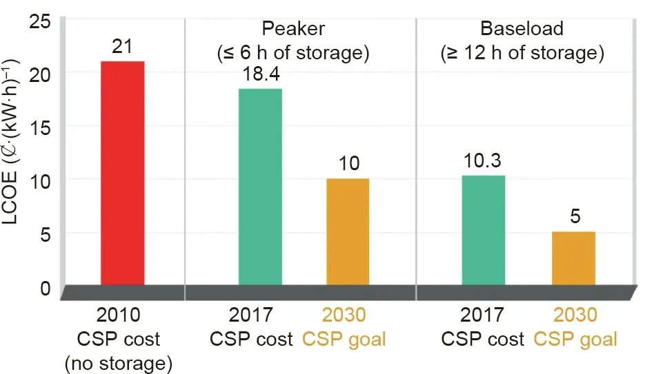
Fig.5.Progress and goals of CSP technology development in the SunShot Initiative of DOE[25].
(1)Molten-salt receiver pathway.It aims to overcome the main technical challenges such as corrosion of construction materials in contact with molten chloride or carbonate salts up to 750°C.After some first examinations,chloride salts were selected for the further development.
(2)Particle receiver pathway.Heat at high temperatures(up to 1000°C)is stored in an inexpensive medium(i.e.,sand-like particles)for low TES costs.The technology gaps such as longterm stability of particles,development of efficient,and low-cost particle-receivers are addressed.
(3)Gas-phase receiver pathway.It utilizes inexpensive gases such as helium as the HTF to transfer heat energy and generate electricity,and stores heat in TES materials like PCM.The main challenges in this pathway include,for example,development of long-term stable power-tower receivers for high temperatures and gas pressures.
In the SunShot Initiative,progress has been made in developing the solid particle TES/HTF technology[27,28],sCO2Brayton power cycle technology[29,30],and molten chloride salt technology[31,32].All of them have promising applications in the next generation CSP technology and other energy-related technologies.In order to test the key components and whole processes under more real conditions,several pilot test plants have been or are being built including the Gen 3 Particle Pilot Plant(G3P3)for the solid particle TES technology[33–35],the Supercritical Transformational Electric Power(STEP)pilot facility for the sCO2Brayton power cycle technology[29],and the Facility to Alleviate Salt Technology Risks(FASTR)for high-temperature molten salt technology[36].Fig.6 illustrates the G3P3 under construction,which will be used to test the key components such as a high-temperature particle receiver[33].Besides designing and constructing the pilot test plants,there was also progress in the material and component development,such as in the particle technology by designing/testing new particle receivers[37]or particle-to-sCO2heat exchanger[38],and in the molten salt technology by collecting/measuring engineering database of molten salts[39]or corrosion control of construction materials in molten chloride salts at high temperatures[40].More information about the fundamental research and technology development of next generation molten chloride salt technology will be shown in Section 3.
2.2.Australia
As one of the countries with the world’s best solar resources,Australia has invested much funding and effort in these years in development of the cost-competitive solar energy technologies.For instance,ARENA started the eight-year initiative—ASTRI—in 2012 to improve the current and develop the future CSP technologies.The leading solar research institutions in Australia such as Commonwealth Scientific and Industrial Research Organization(CSIRO),Australian National University(ANU),the University of Queensland,Queensland University of Technology(QUT),and some innovative companies like Vast Solar,are included in the research program within the framework of ASTRI.Feasibility studies into early stage deployment of CSP technologies have been conducted,and some demonstration plants have been developed in both pilot and commercial environments[8,16,41].In order to support the domestic program of Australia for the next generation CSP technology,ASTRI has collaboration in the aforementioned Gen3 CSP program with US national labs(e.g.,NREL,SNL).The R&D of the next generation CSP technology in Australia focuses on a technology according to the ARENA’s CSP roadmap—liquid sodium as an HTF and different types of materials including PCMs for TES[16,41].Compared to molten salts,liquid sodium is an HTF with higher thermal conductivity,and PCMs can have higher TES density.

Fig.6.G3P3 for testing solid particle TES technology under real conditions[33].1 ft=0.3048 m.
In the research program within the framework of ASTRI,some progress has been made in developing the liquid sodium technology[42],sCO2Brayton power cycle technology[43–45]and novel TES technologies(e.g.,using salt-based PCMs[46–49]and sensible TES materials such as solid particles and molten chlorides[50–52],and study of alloy corrosion in contact with molten salts or saltbased PCMs[53–56]).As shown in Fig.7,a 6 MWthand 1 MWepilot CSP test station located in New South Wales—Vast Solar[57]—started construction in 2014 under the funding of ARENA.In 2019,successful tests with liquid sodium metal as HTF,which has a maximum operation temperature higher than 800°C,were reported[58].Moreover,much effort was made on testing and identifying PCMs for TES in the anticipated higher operation temperature range of the future CSP technology,including the salt mixtures like NaCl–Na2CO3[49]and Li2CO3–K2CO3–Na2CO3[11].The salt-based PCMs have lower prices,higher thermal stabilities and higher TES energy densities than the commercial molten nitrate salts.However,these salt mixtures have low thermal conductivities with heat transfer limitations and show severe corrosion to the construction alloys at their high phase-change temperatures[53–56],which is generally a key problem for the long lifetime of the construction materials.How to mitigate the corrosion effectively and affordably is in progress under extensive investigation,in order to realize the commercial application of these PCMs[53–56].
2.3.Europe
Europe has a long history in the R&D of CSP technologies,and has made a lot of achievements.Spain has the largest installed CSP-capacity in the world(>2.3 GW)in 2019.Since 2004,R&D of CSP technologies including future CSP technologies has been supported by EU in the FP7 and H2020 programs.Some CSP research institutions in Europe such as Spanish Research Center for Energy,Environment and Technology(CIEMAT),German Aerospace Center(DLR),Paul Scherrer Institute(PSI),Swiss Federal Institute of Technology in Zurich(ETH Zurich),Italian National Agency for New Technologies,Energy and Sustainable Economic Development(ENEA),French National Center for Scientific Research(CNRS),and several other institutions are included in these projects.A more complete view of active CSP institutions can be found in the SFERA I–III projects[17–19],as well as the STAGE-STE project[20].
European CSP research infrastructure,strategies,funding schemes,and roadmaps are handled by the European Association for Storage of Energy(EASE),the European Energy Research Alliance(EERA),European Electricity Grid Initiative(EEGI),the European Solar Research Infrastructure for Concentrated Solar Power(EU-SOLARIS),European Research Area Network(ERA-Net),as well as other European and national associations,for example,German Association for Concentrated Solar Power(DCSP)[59,60].Compared to the United States with the Gen3 CSP program,R&D in Europe takes a broader approach,but also addresses the Gen3 CSP technologies.For instance,the main corrosion mechanisms of commercial Fe–Cr–Ni alloys in molten chlorides have been established and some corrosion mitigation methods have shown effective in lab scale[12,14,61–65].Some pilot CSP test plants have been or are being built for the tests of new technologies.For instance,the solid particle TES technology including an advanced particle receiver from DLR is being tested in the experimental CSP plant—Juelich Solar Tower—to receive and store the heat at high temperatures higher than 900°C(Fig.8)[66–68],while liquid metals are tested as high temperature TES/HTF materials in a pilot CSP plant at the Karlsruhe Institute of Technology(KIT)[69–71].In Spain,the molten carbonate salt TES/HTF technology is being tested up to 700°C with six metric tons of ternary eutectic Li2CO3–Na2CO3–K2CO3in an experimental pilot plant called Avanza-2 by Abengoa[10].Besides these works,many more R&D projects are conducted in Europe with European and national funding but not discussed here.
2.4.Asia
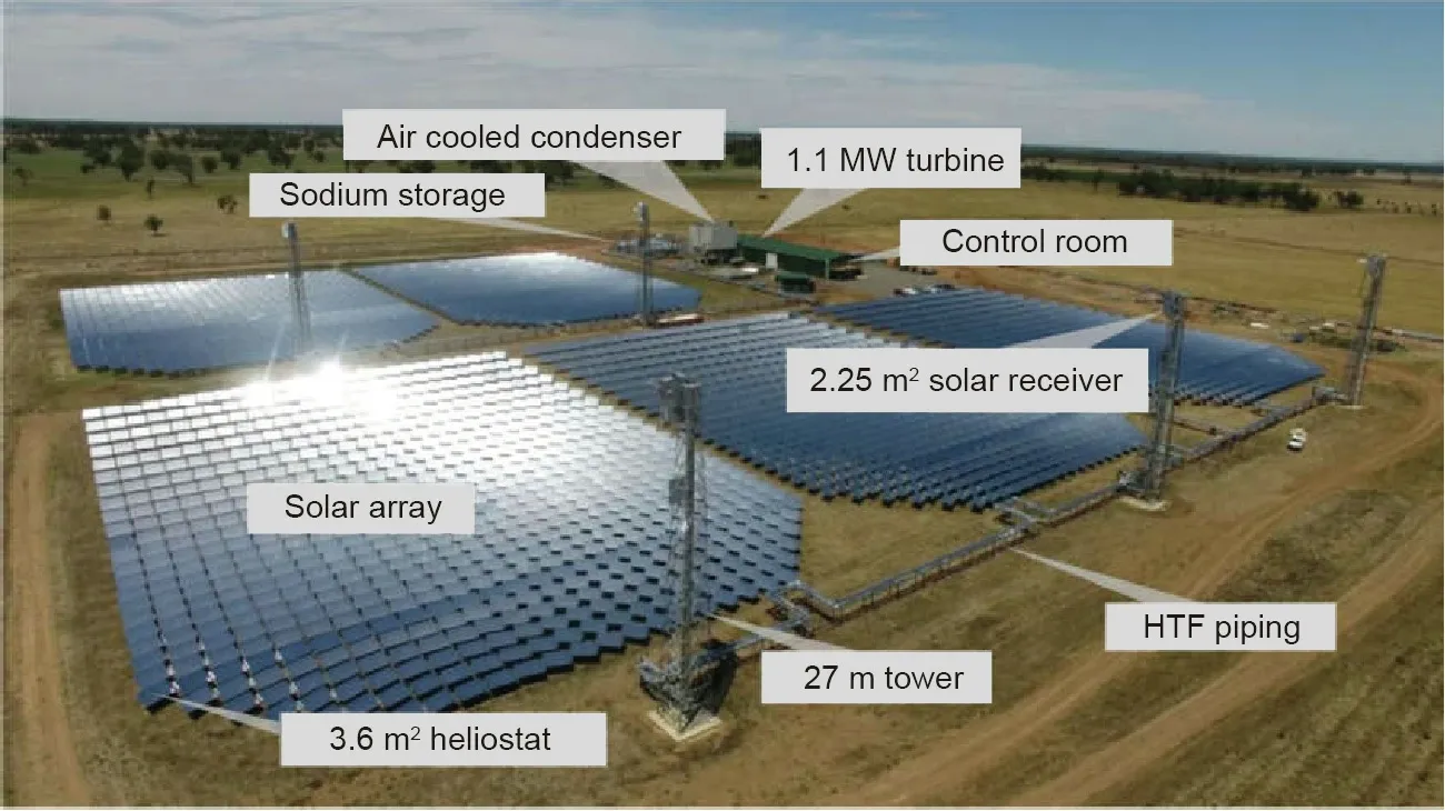
Fig.7.Pilot CSP test station‘‘Vast Solar”located in New South Wales,Australia,which uses liquid sodium metal as HTF and has a designed size of 1 MWe and 6 MWth[58].

Fig.8.DLR’s experimental CSP plant:(a)Juelich Solar Tower and(b)particle receiver CentRec in test[66–68].
Many CSP plants are either operational,under construction,or under development in Asia such as China and India.In 2016,China announced the first group of 20 CSP demonstration projects(1.35 GW)including Zhejiang SUPCON SOLAR Delingha 50 MW molten salt tower project,Beijing Shouhang IHW Dunhuang 100 MW molten salt tower project[24,72].In 2019,most of the new CSP plants around the world(>1.1 GW)were under construction in China.Among~550 MW new operating commercial CSP plants in 2018,China contributed with~200 MW by starting operation of the aforementioned SUPCON SOLAR Delingha 50 MW and Shouhang IHW Dunhuang 100MW molten salt CSPs[24].
With fast development of CSP industries in Asia,mainly in China,the development of new CSP technologies,such as solid particles as TES/HTF[73],molten salts as TES/HTF[21–23],gases as HTF with indirect TES[74],sCO2power cycle[75–77],and solar dish Stirling system[78],is in progress.Recently,the Institute of Electrical Engineering of Chinese Academy of Sciences(IEE-CAS)and research partners including Xi’an Jiaotong University(XJTU),Zhejiang University(ZJU),Tsinghua University(THU),Shanghai Institute of Applied Physics of Chinese Academy of Sciences(SINAP-CAS),and several other institutions started a national research project—‘‘Supercritical CO2Solar Thermal Power Generation,”under the funding within the‘‘National Key R&D Program of China”of MOST of the People’s Republic of China[24].Its key research topics include designing the methods of subsystems in CSP for high temperatures,developing high temperature receivers,developing new TES materials and systems,building the sCO2solar thermal power generation demonstration platform,and material,component,and pilot plant related topics.Moreover,in 2018,one of the Chinese CSP leading manufacturing companies—Shouhang IHW started the collaboration with Electricity of France(EDF)to retrofit Shouhang IHW’s 10 MWeCSP plant with a 10 MWesCO2power cycle CSP in China as a demonstration project of sCO2CSP[77].
The R&D of solar energy technologies in India is mainly handled by the National Institute of Solar Energy(NISE)of India.A current status review on CSP shows that compared to photovoltaic(PV),India has challenges in R&D of the CSP technologies,such as the lack of low availability of skilled labors and indigenous manufacturing[79].Therefore,there is little R&D of the next generation CSP technology in India at the time of writing,though it has high direct normal irradiance(DNI)and much space for solar energy.For countries in Asia such as Japan and Republic of Korea with poor DNI and smaller ground space for CSP,there is more interest in developing solar energy technologies for production of hydrogen overseas(e.g.,in Australia),compared to the next generation CSP.The produced hydrogen can be stored and shipped,and used to produce electricity,heat,or chemicals[80].For instance,in Japan,a solar concentrating test plant is built to test a two-step water splitting process(800–1400°C)for production of hydrogen from solar heat using ceria[81].
2.5.Summary
From 2010 to 2020,under some research programs,remarkable progress has been made in development of the key technologies for next generation CSP such as TES,HTF,and sCO2Brayton power cycle technologies.For instance,almost all these technologies are tested in pilot test plants in either the United States,Australia,Europe,or Asia.The United States has started to build the pilot test plants for testing the molten chloride salt,solid particles,and sCO2Brayton technology under on-sun CSP conditions,while Australia has successfully demonstrated the liquid metal technology for CSP in a pilot plant.Some research institutions and energy companies in Europe are demonstrating the molten carbonate salt,solid particles,and liquid metal technology for CSP.In 2018,China started to build the demonstration sCO2CSP plant close to the commercial scale and testing the key technologies in the sCO2CSP.
The major promising TES/HTF technologies for next generation CSP with operation temperatures higher than current molten nitrate salt systems(up to 565°C)include the following:
·Alternative molten salts as TES/HTF,such as molten chlorides and carbonates with the main current emphasis on the latter due to low costs,
·Solid particles as TES/HTF with first demonstrations in the United States,Europe,and China,
·Gases as HTF(e.g.,helium)and indirect TES(e.g.,solid media,PCMs)with planed demonstrations in the United States,Europe,and China,
·Liquid metals as HTF with different TES options(e.g.,liquid metal itself,solid media,PCMs),demonstrated in Australia and Europe.
The advantages,main challenges,and available demonstration plants of these TES/HTF technologies are summarized in Table 1 for comparison.Among them,molten chloride salt mixtures have suitable melting temperatures and thermal properties,as well as low vapor pressures,high thermal stability,and low costs.Moreover,due to similarity to the commercial molten nitrate salt technology,experience exists from the state-of-the-art CSP power tower design for the next generation CSP plant using alternative molten salts.The particle technology could have maximum operation temperatures up to 1000°C,while the salt-based PCMs technology has a high energy density.Among the HTF technologies,the molten metal technology has a much higher thermal conductivity compared to others.However,these promising TES and HTF technologies meet the technical challenges such as corrosion control of construction materials in molten salts at high temperatures,enhancement of heat transfer and improvement of material recycling stability for solid particles and PCMs,and high costs of materials,operation,and maintenance for liquid metals.Thus,still more R&D effort is needed,for example,more pilot plants or demonstration tests are required to demonstrate the application of these TES technologies in real on-sun environments.
3.Molten chloride technologies for next generation CSP
Molten chloride salts are one kind of the most promising TES/HTF materials in the next generation molten salt technology due to their high thermal stability and low costs.As shown in Table 2[9],the chloride mixtures have high thermal stability(>800°C),comparable thermo-physical properties,but potentially much lower prices,for example,MgCl2/KCl/NaCl(<0.35 USD∙kg-1),compared to carbonate mixtures such as Li2CO3/Na2CO3/K2CO3(1.3–2.5 USD∙kg-1)and commercial nitrate/nitrite mixtures such as Solar Salt(0.5–0.8 USD∙kg-1)[4].However,different from the commercial molten nitrate salt technology,the molten chloride salt technology has one main additional challenge in terms of high corrosiveness of molten chloride salts to the metallic construction materials at high temperatures.Efficient and affordable corrosion control technologies are essential for the molten chloride salt technology.Some review papers on R&D of molten salts as TES/HTF materials are available[3,9,12,82].The following subsections will focus on the recent progress in R&D of the molten chloride salt technology,particularly in corrosion control.
3.1.Salt selection and optimization
Several research groups have performed the selection and optimization of the promising chloride salt mixtures for the next generation molten salt technology by reviewing literature and/or measurements[4,12,32,83–84].Regarding mainly the thermophysical properties and material costs,the following chloride salts are of interest:LiCl,NaCl,KCl,CaCl2,MgCl2,BaCl2,ZnCl2,and AlCl3.As better TES/HTF materials,chloride mixtures generally have lower melting temperatures than single salts.At lower temperatures,mixtures with AlCl3and ZnCl2are of interest since they have low melting temperatures.However,these salts have high vapor pressures and are typically not considered at higher temperatures[83],for example,ZnCl2has high vapor pressures(close to 1 bar(1 bar=1×10⁵Pa)at 720°C)at operating temperatures of the sCO2Brayton cycle in the aforementioned Gen3 CSP concept(T>720°C),while other chlorides like MgCl2have low vapor pressures(<0.01 bar at 800°C)[83].The low vapor pressure is an advantage for TES/HTF applications,since evaporation and condensation of salt in the TES and HTF system is reduced and a pressurized storage tank is not required.Similar to Li2CO3-containing carbonate mixtures,LiCl mixtures show low melting temperatures at the expenses of high costs.Therefore,the ZnCl2-and LiCl-containing chloride salt mixtures are not suggested for the advanced molten salt technology aiming for higher temperatures[4].
The salt mixtures with NaCl,KCl,CaCl2,and MgCl2show promising properties.Compared to other chloride salts,alkali metal chloride salts like KCl and NaCl have high heat capacity,low vapor pressures at high temperatures,weak hygroscopicity(i.e.,less corrosive impurities produced from hydrated water during heating),and low prices,but high melting temperatures(>750°C)[83].Melting temperatures of single alkali metal chloride salts can be significantly reduced by mixing with alkaline earthmetal chlorides(e.g.,MgCl2,CaCl2).The binary mixture with the lowest melting temperature among the salts NaCl,KCl,CaCl2,and MgCl2is KCl–MgCl2[83].This mixture has relatively low melting temperature(426°C),low vapor pressures at high temperatures,and low material costs[83].It can be further improved by addition of inexpensive NaCl to have a lower melting temperature,reduced costs,and increased heat capacity compared to the KCl–MgCl2binary system(Table 2).Fig.9 shows that a eutectic ternary mixture MgCl2/KCl/NaCl has a melting temperature of~383°C with the eutectic composition of 55 wt%/20.5 wt%/24.5 wt% by modeling with the commercial software FactSageTMand differential scanning calorimetry(DSC)measurements[52].Thus,after screening,MgCl2/KCl/NaCl mixture was selected by the leading research groups for the next generation molten salt technology to be the most promising chloride salt mixture[32,52,83,85,86].
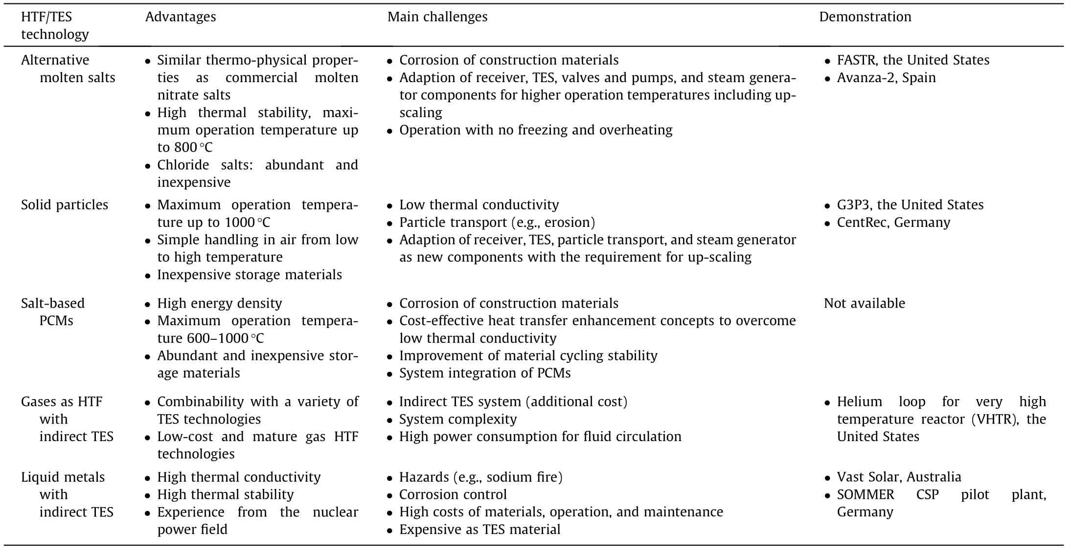
Table 1 Comparison of promising TES/HTF technologies for next generation CSP.

Table 2 Properties and large-scale prices of molten salts as TES/HTF in CSP,adapted from Ref.[9].
3.2.Determination of key molten salt properties
The molten salt properties including minimum melting temperature,vapor pressure,specific heat capacity,density,thermal conductivity,viscosity,and impurities concentration(related to salt corrosivity)are essential for the design of key components including the storage tanks,piping,salt receiver,molten salt pump,molten salt valve,and molten-salt heat exchanger,as well as the corrosion control system.Some effort has been given to define the testing procedures and data analysis criteria for the molten salt properties mentioned above in some research programs such as the SFERA II project[87].The testing procedures and measurement methods for the molten salt properties are summarized in Table 3[9,32,83,87–90].Note that most of the available testing procedures and methods for the molten salt properties are based on the commercial molten nitrate salts[7,87]and some discrepancy among measurement methods exists.Not all of them are suitable for molten chlorides,for example,the determination of maximum operation temperature.For molten chlorides,it should be based not only mainly on the thermal stability as molten nitrate salts,but also on the corrosivity and vapor pressure at high temperatures.
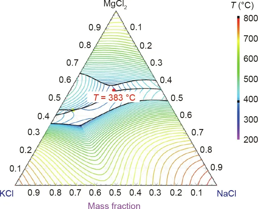
Fig.9.Phase diagram of MgCl2/KCl/NaCl modeled with FactSageTM with a eutectic composition predicted as 55 wt%/20.5 wt%/24.5 wt%,which was also confirmed with differential scanning calorimetry(DSC).Reproduced from Ref.[52]with permission of Elsevier Ltd.,©2018.
In a report from INL,the specific heat capacity,density,thermal conductivity,and viscosity of MgCl2/KCl mixture is reviewed[39].Moreover,NREL and ANU have performed the measurement of minimum melting temperatures of MgCl2/KCl/NaCl via DSC and thermodynamic simulation using FactSageTM[32,52].Wang et al.[88]experimentally investigated the properties of eutectic NaCl/KCl/ZnCl2salt mixture including vapor pressure and viscosity by a homemade set-up and commercial Brookfield viscometer,respectively.For engineering the molten chloride TES technology,Li et al.[89]recommended the equations and correlations for predicting thermo-physical properties of salt mixtures containing NaCl,KCl,MgCl2,CaCl2,and ZnCl2,including heat capacity,density,thermal conductivity,and viscosity,by comparing the calculation results with their experimental data as well as reported in literature.However,the related research work on molten salt properties is still limited for molten chlorides,particularly for the promising MgCl2/KCl/NaCl salt mixture.
3.3.Corrosion studies and control methods for construction materials in molten chloride salts
3.3.1.Corrosion mechanisms and studies of construction materials in molten chloride salts
Strong corrosivity of molten chlorides to the construction materials is the main challenge for realizing their commercial application.The corrosion behavior of construction materials,mainly commercial metallic alloys,in contact with molten chloride salts at high temperatures(>600°C)has been extensively investigated in these years[21,40,61,91,92].Several reviews on this topic have been published recently[9,82,93].A mini-review on corrosion mechanism and control of metallic alloys in molten chlorides published by our group[9]is suggested for more information on this topic.
In theory,the pure chloride salts(e.g.,MgCl2/NaCl/KCl salt mixture)cannot oxidize the metal elements in the commercial Cr–Fe–Ni alloys,since MgCl2,NaCl,and KCl salts are thermodynamically more stable than FeCl2,CrCl2,and NiCl2[14].The oxidative impurities in the molten chlorides such as hydrolysis products lead to severe corrosion of metallic alloys by oxidizing the elements like Cr to form Cr-oxide[9].However,not as in contact with air or hot oxidizing gases,Cr-oxide is dissolvable in molten chlorides by reaction with chloride ions and thus cannot form a protective layer on the commercial Cr–Fe–Ni alloys[14].The studies show that if the salt is not purified,the salt is generally very corrosive at high temperatures.For instance,in contact with unpurified MgCl2/NaCl/KCl chloride salt mixtures at 700°C,even the Ni-based alloys such as Hastelloy C-276 could not fulfill the typical requirements for commercial application(i.e.,corrosion rate<10μm∙a-1for 30 years lifetime)[61].Microstructural analysis on the exposed Cr–Fe–Ni alloy specimens using scanning electron microscopy(SEM)and energy dispersive X-ray(EDX)shows that Cr was dissolved preferentially than Fe and Ni to form a corrosion layer with a porous structure during the corrosion[14].It is generally accepted that the corrosion of metallic construction materials in contact with molten chloride salts at high temperatures is driven by the corrosive impurities in the melt like MgOHCl and the gas phase such as HCl[9,40,82,93].The impurity-driven corrosion mechanism of commercial Cr–Fe–Ni alloys in molten MgCl2/NaCl/KCl salt proposed in our previous work is schematically presented in Fig.10[14].The main corrosive impurity in MgCl2(a strongly hygroscopic chloride)containing chloride salt mixtures is the hydrolysis product MgOHCl from hydrolysis(Eqs.(3)and(4))during dehydration(Eq.(2))[9]:

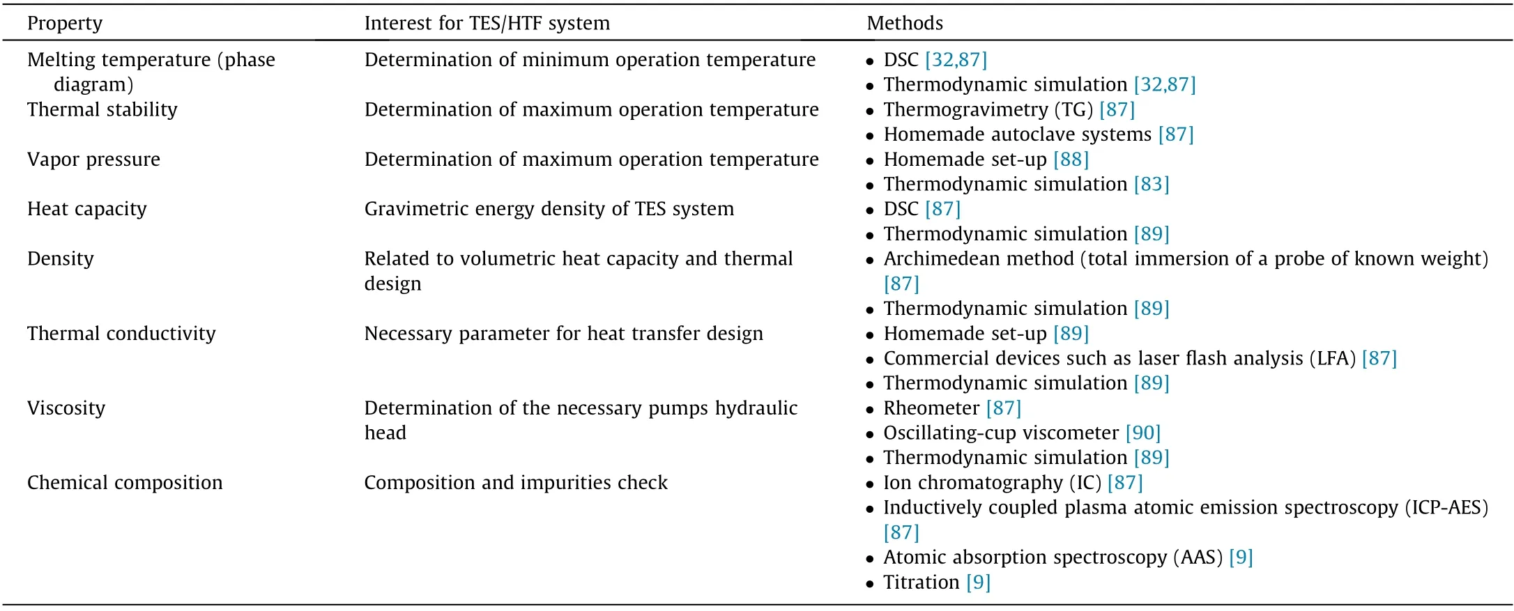
Table 3 Measurement and thermodynamic simulation methods for the molten salt properties essential for designing TES/HTF system.
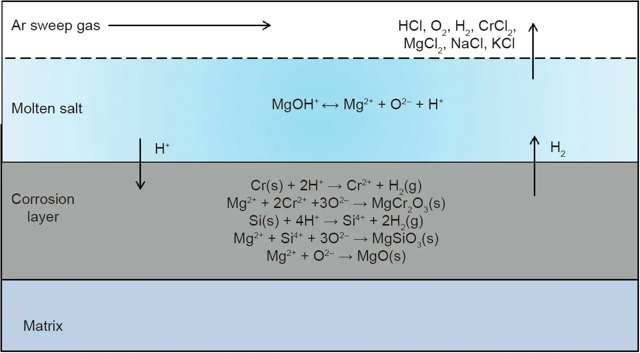
Fig.10.Proposed impurity-driven corrosion mechanism of Cr–Fe–Ni alloys in molten MgCl2/KCl/NaCl salt under inert atmosphere.Reproduced from Ref.[14]with permission of Elsevier B.V.,©2018.
A large amount of MgOHCl can exist in the molten salt in the form of MgOH+and Cl-ions.At temperatures higher than 550°C,MgOH+can decompose to MgO and strongly corrosive H+ions,which reacts with the elements such as Cr and Si in the commercial Cr–Fe–Ni alloys[9].
Besides metallic alloys,some research has been performed on corrosion behavior of ceramic construction materials,such as Al2O3and SiC in molten KCl/NaCl[94],and carbon fiber reinforced silicon carbide(C/C–SiC)composite in molten MgCl2/NaCl/KCl[95]at high temperatures(>600°C).The immersion tests of the C/C–SiC composite in the molten chloride salt show that it has excellent corrosion resistance and therefore is a potentially attractive high-temperature construction material for the key components such as molten salt pumps and valves in the molten chloride salt technology due to its excellent mechanical properties and high fracture toughness at high temperatures[95].
3.3.2.Salt purification
3.3.2.1.Thermal purification.Effort on reducing corrosiveness of the molten chloride salts with strongly hygroscopic chlorides has been made with thermal methods,for example,the corrosive impurities are reduced by suppressing the side reactions of hydrolysis via controlled stepwise salt heating[32,85,96,97].According to the vapor pressure diagram of H2O and HCl over the hydrates of MgCl2(Fig.11),Kipouros and Sadoway[96]used multi-step heating to purify the hydrated MgCl2.By increasing the salt temperature,the hydrated MgCl2at room temperature—MgCl2⋅6H2O was dehydrated to MgCl2⋅4H2O at the temperature T1,MgCl2⋅2H2O at T2,and MgCl2⋅H2O at T3[9,96],sequentially.The salt temperature was controlled between the reaction temperatures of T3and T4(hydrolysis temperature of MgCl2⋅H2O),in order to dehydrate more MgCl2⋅2H2O with water release and without or with limited MgOHCl formation[9,96].A similar purification process was investigated by Vidal and Klammer[32].In a previous work of our group,Maksoud and Bauer[85]investigated the purification of the MgCl2/NaCl/KCl salt mixture(60 mol%/20 mol%/20 mol%)containing hydrated MgCl2(MgCl2⋅6H2O)via DSC,thermogravimetry(TG)coupled to mass spectrometry(MS)and EDX analysis on salts and monitoring produced HCl gas.A salt dehydration approach was tested to reduce the corrosive impurities like MgOHCl by sweeping the solid salt with inert gas below the melting temperature at 350°C before heating above the melting point.
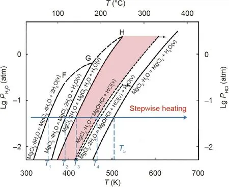
Fig.11.Salt purification by stepwise heating based on vapor pressure diagram of H2O and HCl over the hydrates of MgCl2.1 atm=101 325 Pa.Reproduced from Ref.[96]with permission of Elsevier Science Ltd.,©2001.
However,according to this vapor pressure diagram,completely avoiding the unwanted hydrolysis reactions as shown in Eqs.(3)and(4)is not possible.Even after salt purification with the aforementioned stepwise heating,still a small amount of hydroxide impurities(generally in the range of 0.1 wt%–1 wt%)remains in the salts,which can lead to severe corrosion of metallic construction materials[85–97].The MgOHCl can be dissolved in the molten chlorides in the form of MgOH+and Cl-.MgOH+decomposes further to MgO and corrosive H+at high temperatures(>555°C)[96].The soluble metal–hydroxyl ions are considered to be the most critical corrosive impurities in molten chlorides under inert atmosphere[9,32,40,96].Their concentration should be reduced further by,for example,the chemical or electrochemical salt purification,to a low level to achieve acceptable corrosion rates of construction materials.
3.3.2.2.Chemical purification.Some chemical methods have been used to purify the molten chloride salts.For instance,adding Li metal in LiCl containing molten chlorides[98]or Mg metal in MgCl2containing molten chlorides[62,99]as corrosion inhibitor shows that the corrosion rates of the commercial Cr–Fe–Ni alloys are significantly reduced under static or thermosiphon condition(Fig.12).In our work[62],three commercial high temperature Cr–Fe–Ni alloys(SS 310,Incoloy 800H,and Hastelloy C-276)were exposed to molten MgCl2/NaCl/KCl(60 mol%/20 mol%/20 mol%)mixed salts with 1 wt% Mg as corrosion inhibitor,for 500 h at 700°C under inert atmosphere.By addition of the Mg corrosion inhibitor,the corrosion rates of the studied alloys were found to be significantly reduced by more than 70% compared with the exposure tests without Mg addition.For the corrosion mitigation mechanism,adding Mg metal reduces the concentration of the corrosive impurities MgOHCl and thus reduces the redox potential of the molten chloride salts[62].Recently,Choi et al.[100]used cyclic voltammetry and open circuit potentiometry to investigate this corrosion mitigation mechanism of adding Mg.Sun et al.[86]used the inductively coupled plasma atomic emission spectroscopy(ICP-AES),Raman and infrared spectra to monitor the salt chemistry of molten MgCl2/NaCl/KCl after adding Mg metal.Their results also confirm that adding Mg can remove corrosive impurities MgOHCl and HCl to reduce the corrosivity of salt.
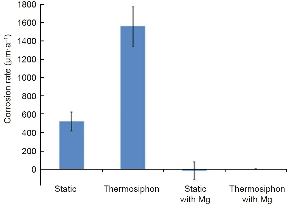
Fig.12.Comparison of corrosion rate for Haynes 230 alloy in molten MgCl2–KCl at 850°C for cases with and without Mg corrosion inhibitor under static and thermosiphon condition[99].
Besides adding corrosion inhibitors,Kurley et al.[40]performed the carbochlorination methods using a variety of carbochlorinating reagents and reagent combinations to purify the KCl–MgCl2molten salt.The molten salt was successfully purified on the kilogram scale by sparging with carbon tetrachloride to trace levels of dissolved oxide(42μmol MgO per kilogram salt).Fig.13[40]shows that in such purified molten chloride salt SS 316L has the similar low corrosion rate as Ni-based Hastelloy N at 700°C.Both corrosion rates are less than 30μm∙a-1(mass change after 100 h immersion<0.2 mg∙cm-2)close to the requirement for 30-year lifetime.This also reveals that the corrosive impurity in the molten chloride salt has a dominant corrosion effect.If the concentration of the impurity is controlled below an acceptable level,it seems feasible that affordable construction materials like stainless steels can be used in the next generation molten chloride TES system to ensure its cost competitiveness.
3.3.2.3.Electrochemical purification.Electrochemical purification methods based on electrolysis have been studied to purify the molten chloride salts.It is shown in Refs.[101–103]that most impurities in the molten chloride salts can be removed by the preelectrolysis(PE)using inert electrodes.However,the following reactions will take place to produce the toxic gases like Cl2if the inert electrodes are used:

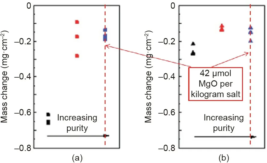
Fig.13.Mass change for(a)SS 316L and(b)Hastelloy N exposed to KCl–MgCl2 salt with low(black),moderate(red),and high(blue)purities at 700°C under inert atmosphere.Reproduced from Ref.[40]with permission of the Royal Society of Chemistry,©2019.
Moreover,the electrodes are passivated by produced electrically insulating solid MgO.Recently,in order to avoid the production of toxic Cl2and the electrode passivation,a Mg anode and a pulsed potential are used in the electrolysis by the authors[104]to purify the molten MgCl2/KCl/NaCl chloride salt for reducing its corrosivity according to the following reactions:

These reactions and observed phenomena in the electrolysis with a Mg anode are schematically presented in Fig.14.The results show that the corrosive impurity MgOHCl is efficiently removed by electrolysis,and the potentiodynamic polarization(PDP)measurements on a commercial high-temperature alloy(Incoloy 800 H)immersed in the molten salt indicate that the corrosion rate of the alloy is significantly reduced due to the salt purification[104].Moreover,a pulsed potential applied on the tungsten cathode during electrolysis shows that it could reduce the cathode deactivation due to produced MgO on the surface[104].This electrochemical salt purification method has shown to be promising for affordably controlling the corrosivity of the molten chloride salt.
3.3.2.4.Measurement and monitoring methods for corrosive impurities.In order to measure or monitor the concentration of corrosive impurities such as MgOHCl in the MgCl2-containing molten chlorides,several methods such as titration[40,61]and cyclic voltammetry(CV)[61,101]have been investigated.Kurley et al.[40]used the titration method via micropipettes and a commercial pH electrode to measure the concentration of dissolved MgO/MgOHCl in the KCl–MgCl2molten salt.The measurement limit can be below 50μmol MgO per kilogram salt,that is,5 ppm in weight for MgOH+.Skar[101]and our previous work[61]showed the CV method to be a promising in-situ monitoring method for the MgOH+impurity with the measurement limit of~100 ppm in weight MgOH+.Fig.15 shows a typical cyclic voltammogram for molten MgCl2/KCl/NaCl salt with impurity ion MgOH+.The CV and titration measurements indicate that the peak current density peak ipof the reaction B(MgOH++e-→MgO(s)+(1/2)H2(g))is proportional to the bulk concentration of MgOH+in the molten chloride salt.Other methods like the aforementioned Raman and infrared spectra method were also used to measure or monitor the MgOH+impurity[86].Compared to the chemical post-analysis methods,the in-situ monitoring methods can be developed to a monitoring technique,which can be integrated with the aforementioned salt purification techniques to build up an efficient corrosion control system for the molten chloride TES system.
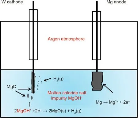
Fig.14.Schematic of assumed reactions and observed phenomena in the electrochemical salt purification using Mg anode of KCl/MgCl2/NaCl mixture at 500°C under inert atmosphere.Reproduced from Ref.[104]with permission of Elsevier B.V.,©2019.
3.3.3.Other corrosion mitigation methods
Besides the salt purification,some corrosion mitigation methods by modifying the construction materials such as coating a protective layer such as Al2O3[62,105–107],yttria-stabilized zirconia(YSZ)[108],Fe-based or Ni-based amorphous coatings[109],have been investigated and shown to be promising.Compared to the salt purification approaches,the protective layer of the alloy can mitigate corrosion of the alloy in contact with both the liquid and vapor phases of the molten chlorides[105].Gomez-Vidal et al.[105–107]formed dense and continuous alumina layers on the alloys by pre-oxidizing them at high temperatures(e.g.,1050°C),which could protect the alloys from corrosion of the molten chloride salts.Moreover,Raiman et al.[109]showed that the Fe-based or Ni-based amorphous coatings can improve the corrosion resistance of construction alloys in corrosive molten chloride salts.In our previous work[62],a protective alumina layer was formed on the surface of a Fe–Cr–Al(8 wt%)model alloy by pre-oxidation in air at high temperatures(800°C).As shown in Fig.16,the adherent alumina scales can effectively inhibit the dissolution of Cr and Fe and the bulk penetration of corrosive impurities[62].
4.Conclusions and prospects
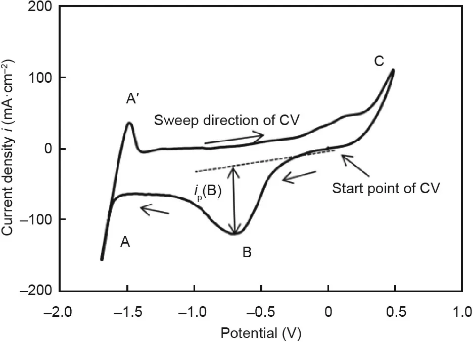
Fig.15.Typical cyclic voltammogram for molten MgCl2/KCl/NaCl salt with impurity ion MgOH+.Reaction A:Mg2++2e-=Mg(s);Reaction A′:Mg(s)=Mg2++2e-;Reaction B:MgOH++e-=MgO(s)+(1/2)H2(g);Reaction C:Cl-=(1/2)Cl2(g)+e-.T=500°C;working electrode:tungsten;sweep rate:200 mV⋅s-1.ip(B):peak current density for reaction B.Reproduced from Ref.[61]with permission of Elsevier Ltd.,© 2017.
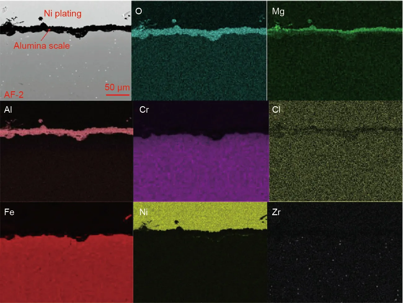
Fig.16.SEM cross section image and EDS mapping of a pre-oxidized Al-containing Fe–Cr–Al(8 wt%)model alloy after the corrosion experiment in molten MgCl2/KCl/NaCl salt at 700°C for 500 h under inert atmosphere.Reproduced from Ref.[62]with permission of Elsevier B.V.,©2018.
From 2010 to 2020,remarkable progress was achieved in the R&D of the next generation CSP with new TES/HTF technologies at elevated temperatures under the funding of different initiatives and research programs in many countries/regions including the United States,Australia,Europe,and Asia(mainly China).In the next generation CSP plants,new TES technologies for temperatures higher than 565°C were developed and could be integrated in power cycles with higher heat to electrical conversion efficiencies(e.g.,sCO2power cycle technology)in future.Four main kinds of promising technical concepts have been researched intensively including solid particles as TES/HTF,molten salts(especially chlorides)as TES/HTF,gases as HTF(e.g.,helium)with indirect TES(e.g.,solid media,PCMs),and liquid metals as HTF with different TES options(e.g.,PCMs).This review summarized the recent R&D progresses and main challenges of these technologies.In addition,the advantages and disadvantages of these technologies were compared and commented critically.
Among these candidate materials,molten chloride salts are considered the most promising TES/HTF materials for the next generation molten salt technology,which can be operated at up to 750°C,due to their excellent thermal properties and low costs.However,molten chlorides are high corrosive to the metallic construction materials at high temperatures,imposing the challenges which need to be addressed.Progresses in the R&D of the molten chloride TES/HTF technology are summarized as:
(1)MgCl2/KCl/NaCl was identified as the most promising chloride salt mixture;
(2)Measurement methods and recommended values of molten salt properties(i.e.,minimum melting temperature,vapor pressure,specific heat capacity,density,thermal conductivity,viscosity,and corrosivity)essential for engineering the molten chloride technology have been determined partially,but not yet fully;and
(3)Corrosion mechanisms were investigated and relevant corrosion control measures were developed.
Based on the review of the state-of-the-art,future work,which could help to realize the practical application of the molten chloride TES/HTF technology in the next generation CSP technology,is suggested:
(1)Co-development of salt purification and corrosion mitigation methods for efficient and affordable corrosion control in the process;
(2)Development of effective corrosion control methods;
(3)Identification of suitable construction materials to be tested(at laboratory scale)for their durability and corrosion in chloride mixtures with different impurities;
(4)Development of all key units in the molten salt loop,such as storage tanks,heat exchanger,piping,pumps,and valves,as well as their pilot demonstration at elevated temperatures;
(5)Identification of strategies to scale up the whole technology including materials and processes toward applications in practice.
Acknowledgments
This research has been performed by funding of the German Federal Ministry for Economic Affairs and Energy(BMWi)and within the DLR and German Academic Exchange Service(DLR-DAAD)fellowship program.The author W.Ding would like to thank Dr.Xiaolei Fan and Dr.Reza Vakili at the University of Manchester for proofreading the revised manuscript.
Compliance with ethics guidelines
Wenjin Ding and Thomas Bauer declare that they have no conflict of interest or financial conflicts to disclose.
- Engineering的其它文章
- Evaluation Method and Mitigation Strategies for Shrinkage Cracking of Modern Concrete
- One-Step Preparation of Green Fabric for Continuous Antibacterial Applications
- Process Intensification in Pneumatically Agitated Slurry Reactors
- Extreme Learning Machine-Based Thermal Model for Lithium-Ion Batteries of Electric Vehicles under External Short Circuit
- Fundamentals and Processes of Fluid Pressure Forming Technology for Complex Thin-Walled Components
- New Standards Release Sets Stage for 5G Future

