
Preparation and Improvement of Electrochemical Performance of Li1.26 Fe0.22Mn0.52O2 Fe-Mn Based Li-Rich Cathode Materials in-Situ Coated with Conductive Polypyrrole
2021-05-16 01:39:14HOUChenLZhiXIAOXiangZHAOYuJuan100124
无机化学学报 2021年5期
HOU ChenLÜ ZhiXIAO Xiang ZHAO Yu-Juan( 100124)
Abstract:Nano-sized Li1.26Fe0.22Mn0.52O2(LFMO)cathode material coated with conducting polypyrrole(PPy)was successfully synthesized by simple chemical oxidative polymerization.The crystal structure of the sample was examined by X-ray diffraction(XRD),and the morphology and micro-structure were observed by scanning electron microscopy(SEM)and transmission electron microscopy(TEM).The elemental mapping and Fourier transform infrared spectrometer results demonstrated that the conductive network of PPy was present in the composites and PPy was uniform ly distributed on the LFMO particles.The electrochemical properties of all of the samples were investigated by galvanostatic charge-discharge test and electrochemical impedance spectroscopy(EIS)analysis,which showed that the PPy on the surface significantly decreased the charge-transfer resistance of LFMO.LFMO coated with mass ratio of 2% PPy(LFMO-2% PPy)exhibited excellent rate performance and good cycle stability.The initial discharge capacity was 206 mAh·g-1 at the 1C rate,and the initial coulombic efficiency was 87%.After 50 cycles at 1C and 2C,the capacity stabilized at 131 and 139 mAh·g-1,respectively.
Keywords:Fe-Mn based Li-rich cathode material;polypyrrole coating;electrochemical performance;lithium-ion batteries
0 Introduction
Lithium ion batteries (LIBs) are attractive rechargeable batteries due to their high energy density[1].However,conventional cathode materials such as layered LiCoO2[2-3],olivine LiFeO4[4-5]and spinel LiMnO4[6-7]cannot meet the demands of high energy density and high power density for electric vehicles.In recent years,there has been an increasing interest in Mnbased Li-rich cathode materials(xLi2MnO3·(1-x)LiMO2(M=Ni,Co,Fe…))for Li-ion batteries,because these materials can provide high capacity,lower cost,higher safety and thermal stability[8-9].Among these,Fe-Mn based Li-rich materials are interesting potential cathode materials,because Fe and Mn are environmentallyfriendly and earth-abundant and Fe-Mn based Li-rich materials exhibit a unique mechanism of initial chargedischarge of Li-rich layered oxide to obtain its high capacity[10-11].However,Fe-Mn based Li-rich materials have several intrinsic shortcomings such as complicated synthesis,poor rate performance,and capacity fading that greatly limit their practical applications[12-13].
Complicated synthesis routes can be used to obtain nanoparticles of the Fe-Mn Li-rich cathode material,thus decreasing the lithium ion diffusion length and improving the rate performance.While nanocrystalline particles possess a high specific surface area to provide more Li+de/insertion sites,such particles also have a greater likelihood of reaction with the liquid electrolyte during the high operating voltage(>4.5 V)that may damage the cycle stability.Additionally,the poor rate performance of these materials is also due to the low electronic conductivity of insulating Li2MnO3[14]that is the dominant component of materials.
Surface modification with electrochemically inert materials has been found to be a fruitful approach for enhancing the electrochemical performance of cathode materials[15-16].ZrO2[17],ZnO[18],TiO2[19]and Al2O3[20]have been employed as coating materials for the surface modification of Li-rich cathode materials to improve their cyclability and thermal stability at high charge potential.However,such surface modifications cannot significantly enhance the electronic conductivity.The use of a conductive carbon coating has been reported as another strategy for the surface modification of cathode materials[21],but this approach is still difficult to apply to Li-rich cathode materials because a reducing atmosphere is necessary for the carbonization of the carbon source at high temperature.Due to its good environmental stability,high electrical conductivity and easy preparation,polypyrrole(PPy)has been coated on cathode materials with low conductivity such as LiFePO4/PPy[22],Si/PPy[23]to improve their rate performance and cycling stability.Meanwhile,PPy coatings have been used as the protective layer in different materials such as ZnCo2O4/PPy[24],LiNi0.5Mn1.5O4/PPy[25],LiMn2O4/PPy[26]in order to suppress the occurrence of side reactions on the surface of the electrode material with the electrolyte.
In this work,we have successfully prepared nanoparticles of Li1.26Fe0.22Mn0.52O2(LFMO)with PPy coating via simple chemical oxidative polymerization.The synthesis is simple and facile and does not involve a hightemperature treatment.The electrochemical properties of the pristine and the PPy-coated LFMO as cathode materials for Li-ion batteries were also investigated in detail.
1 Experimental
1.1 Synthesis of nano-particles LFMO
LFMO was prepared by the low-temperature molten salt method as reported previously[27].Stoichiometric amounts of the LiCH3COO·2H2O,Mn(CH3COO)2·4H2O and Fe(NO3)3·9H2O salts were mixed in a beaker with a molar ratio of 5% excess of LiCH3COO·2H2O used to compensate lithium evaporation losses.Then,these materials were heated to their melting temperature(80℃)for 30 min in a water bath with mechanical stirring.The obtained black sand-like mixture was preheated at 200℃in an oven for 10 h to obtain the precursor.The precursor LFMO was sintered at 500℃in air for 5 h and cooled to room temperature to obtain LFMO nanoparticles.
1.2 Preparation of PPy-coated LFMO(LFMOPPy)
PPy was coated on the LFMO composite powders by the chemical polymerization method.A stoichiomet-ric amount of the sodiump-toluenesulfonate(TSNa,AR,98%)used as the dopant and pristine LFMO were ultrasonically dispersed in an alcohol solution.Then,liquid pyrrole monomer(AR)was added into the reactive solution.Finally,an aqueous solution of FeCl3·6H2O(AR,99%)acting as the oxidant was dropped into the above solution under continuous magnetically stirring for 6 h in an ice/water bath(0~5℃).The final products were filtered and washed with deionized water for several times,and dried at 80℃in a vacuum oven overnight(the PPy content was mass ratio of 2%,and the obtained sample was denoted as LFMO-2% PPy).This synthetic route is illustrated in Scheme 1.
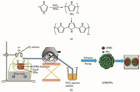
Scheme 1 (a)Polymerization reactions of pyrrole monomer,and the chemical structure of PPy;(b)Schematic diagram of the preparation of the Fe-Mn based Li-rich materials in situ coated with PPy
1.3 Electrochemical measurements
The electrochemical characterizations were carried out using CR2032 coin type cells assembled in an Ar-filled glovebox.The electrolyte was 1 mol·L-1LiPF6dissolved in a mixture(1∶1,V/V)of ethylene carbonate(EC)and dimethyl carbonate(DMC)solvents.Glass microfiber filters were used as the separator.The cathode electrode was composed mass ratio of 80% active material,10% carbon black and 10% polytetrafluoroethylene.The galvanostatic charge/discharge profile was measured in a voltage range of 2.0~4.8 V at 0.2C,1C,2C and 3C(1C=200 mA·g-1)at room temperature for 50 cycles using a multichannel battery testing system(Neware,Shenzhen,China).Cyclic voltammogram measurements were carried out between 2.0 and 4.8 V at a scanning rate of 0.1 mV·s-1.Electrochemical impedance spectroscopy(EIS)was performed using an electrochemical workstation (VMP3,Biologic,France).The impedance spectra were obtained at an amplitude of 5.0 mV over the frequency range of 100 kHz to 10 mHz.
1.4 Structure characterization
The crystal structure of the samples was evaluated by X-ray diffraction(XRD,Bruker D8 Advance,Bruker,Germany)using CuKαradiation at room temperature(λ=0.154 2 nm)at a voltage and current of 40 kV and 40 mA,respectively.The scan data were collected in the 2θrange of 10°~80°at a scan rate of 2(°)·min-1.The presence of PPy was confirmed using a Fourier transform infrared spectrometer(FTIR,Bruker Vertex 70,Bruker,Germany)by observing the characteristic peaks assigned to the corresponding chemical bonds of PPy composites.The morphology of the samples and element mapping was characterized by scanning electron microscopy(SEM,JSM 4300,JEOL,30 kV).For transmission electron microscopy(TEM)analysis,the samples were dispersed in EtOH,and then transferred onto Cu grids for further analysis.TEM images of the samples were recorded using a field-emission transmission electron microscope.X-ray photoelectron spectroscopy(XPS,Kratos Analytical Ltd.)was performed with monochromatized AlKαradiation and an energy resolution of 0.48 eV.
2 Results and discussion
Fig.1 shows the XRD patterns obtained for LFMO and LFMO-2% PPy.All of the diffraction peaks were sharp and well-defined,showing that the composites powders are well-crystallized.The patterns can be indexed based on the hexagonalα-NaFeO2structure(Rmspace group),except for the weak superstructure peaks appearing between 20°and 22°that are mainly due to the Li2MnO3structure in the solid solution[28].Due to the low content of PPy,no significant change was observed after the application of the PPy coating,and no considerable secondary phase was formed.The lattice parameters of LFMO and LFMO-2% PPy were calculated and are shown in Table 1.No clear difference was observed between the LFMO results and the LFMO-2% PPy results.This suggests that the introduction of the PPy-coating did not change the crystal structure of the pristine LFMO.
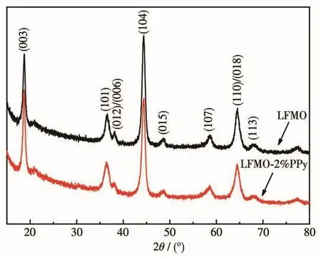
Fig.1 XRD patterns of LFMO and LFMO-2% PPy
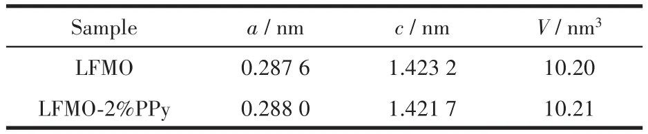
Table 1 Lattice parameters of LFMO and LFMO-2% PPy
The PPy content in the composite was determined by thermogravimetric analysis(TGA)(Fig.2a).During TGA testing,the samples were heated from 0 to 600℃at rate of 10℃·min-1.In agreement with the reports in the literature,the PPy polymer begins to decompose at approximately 200℃and the decomposition continued until the complete decomposition at 550℃.Pristine LFMO retained a constant weight with increasing temperature.Hence,based on the TGA results for LFMO-2% PPy,the coated PPy was estimated to have the mass fraction of 2%.The FTIR spectra of the samples are shown in Fig.2b.The coated sample shows the characteristic absorption peaks of PPy.The peak at 1 558 cm-1corresponds to the C=C stretching vibration,the peak at 1 504 cm-1corresponds to the C—N in-plane deformation vibration,and the peaks at 1 384,1 301,and 1 035 cm-1correspond to the C—H out-of-plane asymmetric vibrations[24].It is confirmed that PPy was successfully coated onto the surface of the LFMO materials.
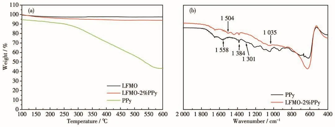
Fig.2 (a)TGA curves and(b)FTIR spectra of the samples
SEM images of the LFMO and LFMO-2% PPy samples are shown in Fig.3a~3d.Examination of the SEM images reveals that the particle size of the samples was approximately 100 nm.Fig.3a~3d show that the aggregation of pristine LFMO was more severe than that of LFMO-2% PPy.
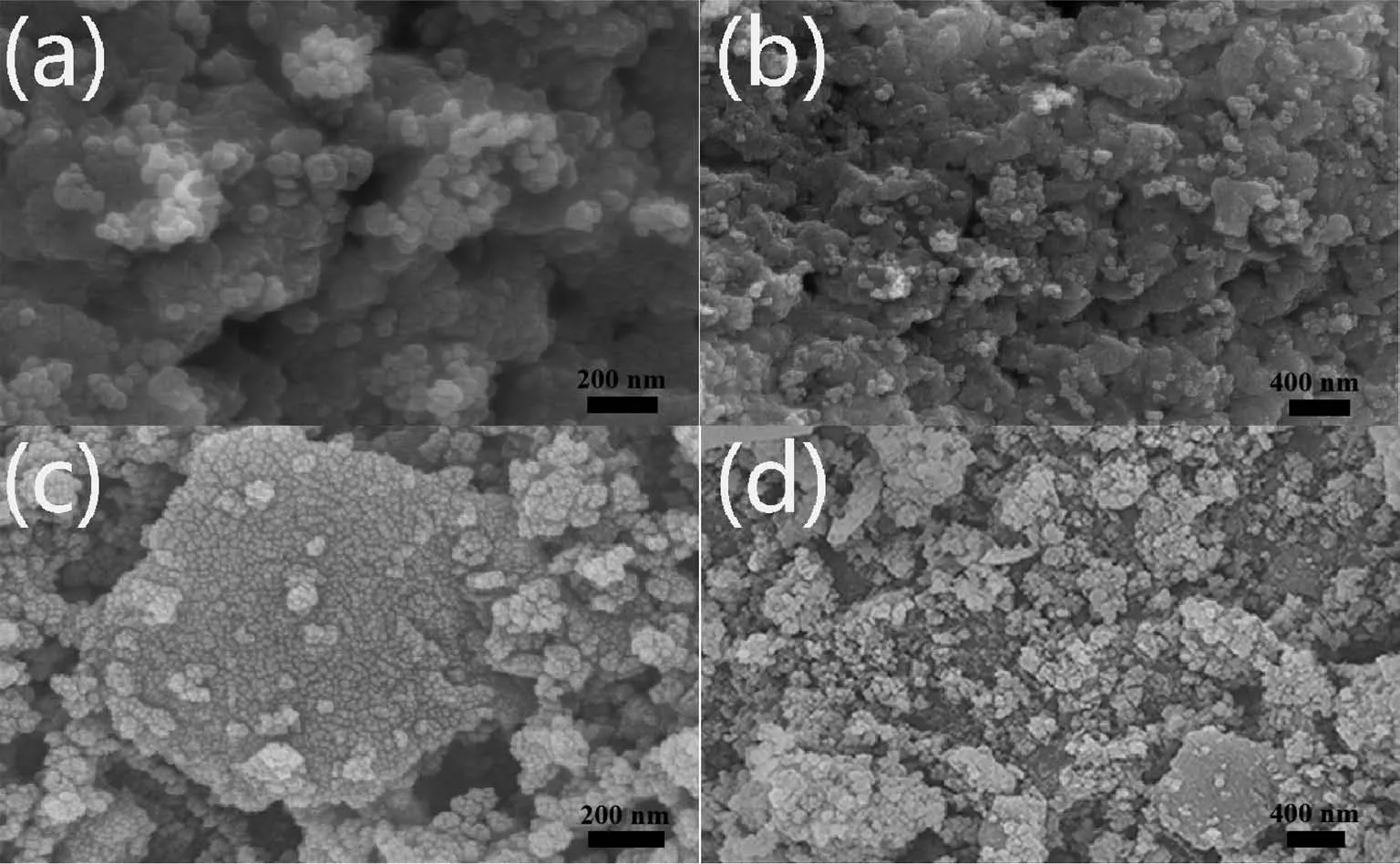
Fig.3 SEM images of(a,b)LFMO and(c,d)LFMO-2% PPy
The TEM images of the pristine LFMO and LFMO-2% PPy are shown in Fig.4 with the corresponding high resolution transmission electron microscopy(HRTEM)image shown in Fig.4c.From the TEM images,the lattice spacing was measured to be 0.47 nm,which is the typical value of the layered(003)fringes of theRmstructure.The results also confirmed that the structure of the pristine LFMO will not be affected by the coating PPy powders.Moreover,as shown in Fig.4c,a thin amorphous PPy coating adhered to the particles surface,and the coated LFMO maintained excellent crystallinity.To observe the distribution of PPy on the particle surface,energy dispersive spectroscopy(EDS)mapping was conducted with the results for the elemental mappings of the selected area acquired from the scanning TEM(STEM)images and of the LFMO-2% PPy particles shown in Fig.5.The light spots correspond to the presence of Fe,Mn,O,N and C in the sample that were uniformly distributed in the composite with the same shape as that of the STEM image.The elemental mapping results indicate that the conducting PPy covered the LFMO surface.
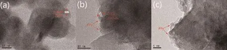
Fig.4 TEM images of(a)LFMO and(b)LFMO-2% PPy;(c)HRTEM image of LFMO-2% PPy
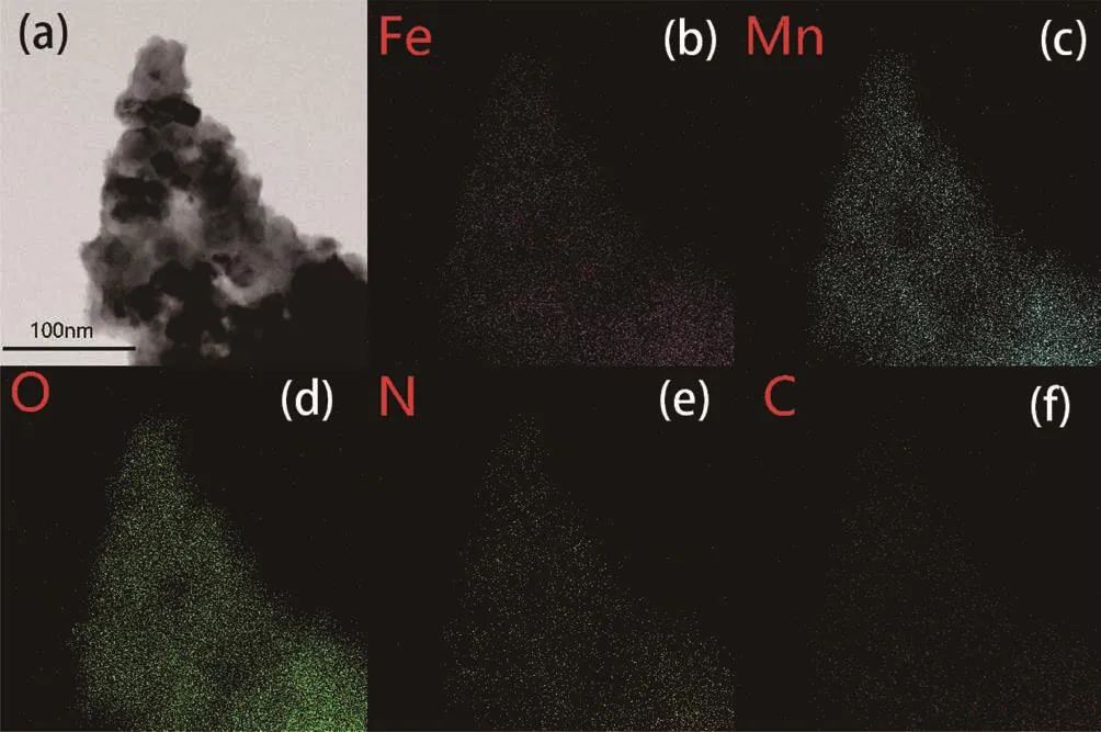
Fig.5 (a)STEM image of LFMO-2% PPy and elemental mappings of Fe(b),Mn(c),O(d),N(e)and C(f)
XPS was used to determine the surface chemical compositions and the oxidation states of the elements of the pristine LFMO and LFMO-2% PPy.Fig.6a depicts the full spectra of the samples that display signals corresponding to the Fe,Mn,O,N and C species.As shown in Fig.6b,the Fe2p3/2and Fe2p1/2spectra exhibited two main peaks with the binding energies of 710.9 and 725.0 eV,respectively,that can be assigned to Fe3+[29].Another two peaks at 719.6 and 732.2 eV are satellite peaks that should also be attributed to Fe3+[29].In Fig.6c,the main peaks of Mn2p3/2and Mn2p1/2are found at the binding energies of 642.0 and 653.9 eV,corresponding to the Mn4+state[13].Fig.6d shows that the main peak of O1swas located at 529.5 eV corresponding to the lattice oxygen of the LFMO materials,and the peak with the binding energy of 531.4 eV is attributed to oxygen in Li2CO3that is present as an impurity on the surface of LFMO.Compared to the pristine LFMO,LFMO-2% PPy showed no evident impurity Li2CO3signal.This is most likely due to the weak effect of the acid-hydrolysed FeCl3appearing on the sample due to corrosion in acidic conditions for which H+-Li+exchange and dissolution reaction occurs on the surface of the material[30].Hence,the XPS results show that the predominant oxidation states of Fe and Mn in the composite were+3 and+4,respectively.In Fig.6e,the characteristic peaks at 406.9 eV[31]of the N element indicates the existence of PPy in LFMO-2% PPy.
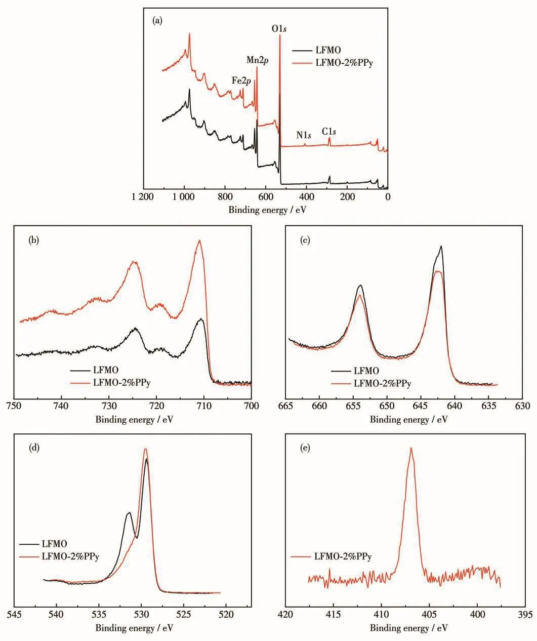
Fig.6 XPS spectra:(a)full spectra,(b)Fe2p,(c)Mn2p and(d)O1s of LFMO and LFMO-2% PPy,and(e)N1s of LFMO-2% PPy
Fig.7a and 7b compare the first charge-discharge cycles of the pristine LFMO and LFMO-2% PPy materials at 1C and 2C at 2.0~4.8 V.As shown in Fig.7a and 7b,the plateau at 4.5 V appeared in the initial charge curve,suggesting the charge characteristics of the Lirich cathode materials.The charge curve below 4.5 V is attributed to Li extraction from the LiFeO2component corresponding to the oxidation of Fe3+to Fe4+,and the plateau above 4.5 V is due to the Li2O extracted from the Li2MnO3component[32].The special charge mechanism of the Li-rich cathode materials is regarded as the origin of the high capacity and leads to initial irreversible capacity loss.Both the pristine and coated LFMO samples had a high discharge capacity of approximately 200 mAh·g-1.Compared to the LFMO,the initial charge capacity of LFMO-2% PPy was much lower than that of pristine LFMO(236 vs 355 mAh·g-1),and the initial coulombic efficiency of PPy-coated materials was 87%,but that of the pristine sample was only 57%(Table 2).It is possible that the acidic PPy coating process activates the surface of the LFMO sample to shorten its 4.5 V plateau,and therefore improves the initial coulombic efficiency.The cycling performances of the LFMO and the LFMO-2% PPy were compared in Fig.7c and 7d.It is clearly observed that the discharge capacity of LFMO-2% PPy was retained at 131.0 mAh·g-1after 50 cycles,while the discharge capacity of the pristine LFMO faded quickly to 93 mAh·g-1after 50 cycles at 1C.Similar trends can also be observed at 2C in Fig.7d.The LFMO-2% PPy still maintained 139 mAh·g-1after 50 cycles,while the pristine LFMO faded to 75 mAh·g-1.The improved rate performance shows that the conductive PPy coating is beneficial for Li+and electron diffusion.
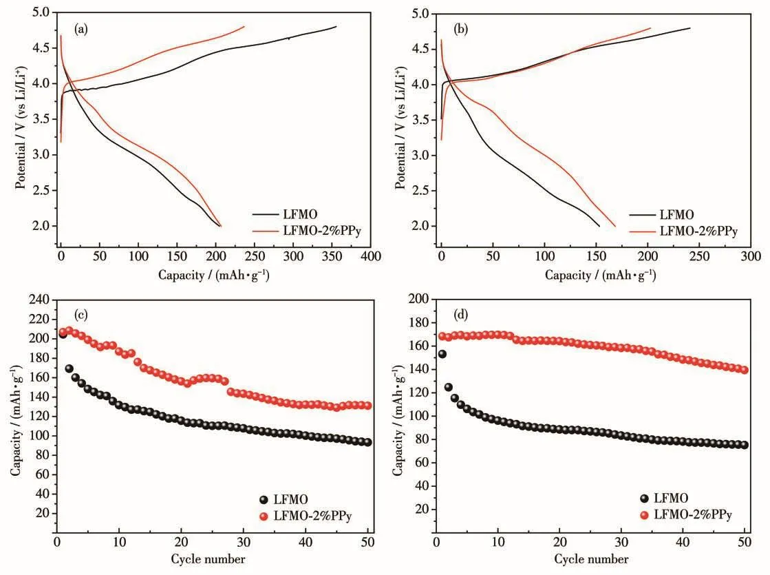
Fig.7 Initial charge/discharge voltage profiles of the samples at 1C(a)and 2C(b);Cycling performances of the LFMO and LFMO-2% PPy at 1C(c)and 2C(d)
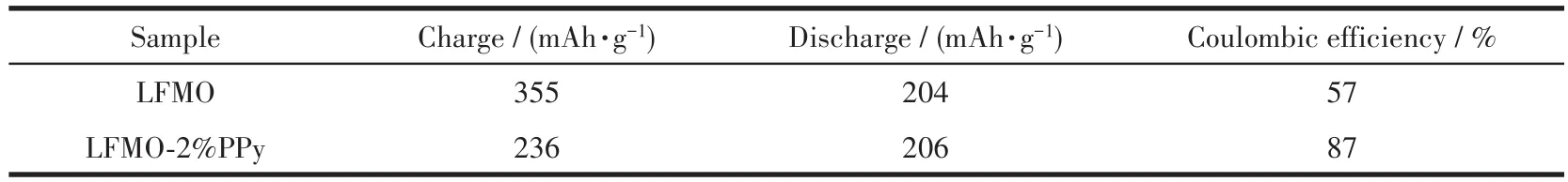
Table 2 Initial performance of LFMO and LFMO-2% PPy at 1C
To further investigate the electrochemical performance of the LFMO and LFMO-2% PPy composite electrodes,the rate capability was tested and the results are shown in Fig.8.The rate performance was evaluated by a multiple step galvanostatic strategy at various rates ranging from 0.2C to 5C at the voltage limit of 2~4.8 V.For each stage,the testing was carried out for 5 cycles.Fig.8a shows that the pristine LFMO exhibited poor rate performance and the discharge capacity dropped sharply with increasing discharge current density,particularly at higher rates.The discharge capacity of LFMO-2% PPy was higher than that of pristine LFMO at all rates(Fig.8b).Additionally,the average discharge potential of the pristine LFMO droped from 3.24 to 2.40 V when the charge-discharge current rate increased from 0.2C to 5C.For LFMO-2% PPy,as shown in Fig.8b,the average discharge potential decreased from 3.27 to 2.50 V,suggesting that the potential stability enhancement is related to the facilitation of Li+migration due to the presence of the PPy coating[33].With increasing rates,the discharge capacities of the LFMO and LFMO-2% PPy composites gradually decreased.The discharge capacities of the pristine LFMO after 5 cycles at 0.2C,0.5C,1C,2C,3C and 5C were 222,170,131,99,78 and 48 mAh·g-1,respectively,while the discharge capacity of LFMO-2% PPy at these rates showed higher values of 257,215,176,139,114 and 83 mAh·g-1.Moreover,after deep cycling at 5C,the discharge capacity of LFMO-2% PPy of 198 mAh·g-1was still retained after 5 cycles when the testing rate was decreased back to 0.2C.Comparison to the rapidly decreasing discharge capacity of the LFMO(159 mAh·g-1after 5 cycles)shows that LFMO-2% PPy has a much better rate capability than the pristine LFMO.This is due to the beneficial effects of the PPy conductive layer for Li+diffusion and transport and effective reduction in the electrode resistance.
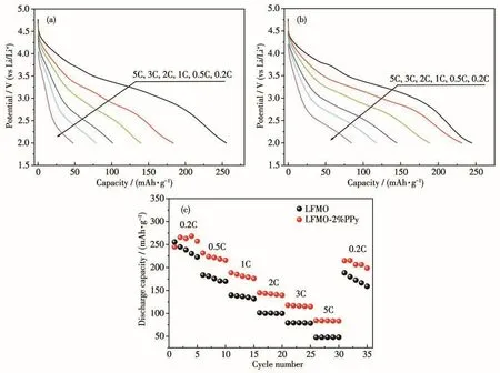
Fig.8 Discharge curves of(a)LFMO and(b)LFMO-2% PPy at different rates;(c)Step rate capability of LFMO and LFMO-2% PPy at room temperature in the 2~4.8 V range
Fig.9 shows the cyclic voltammetry curves of the LFMO and LFMO-2% PPy in a range of 2~4.8 V obtained at a scan rate of 0.1 mV·s-1.For all of the samples,the main oxidation peak was located at 4.1 V and the reduction peak was found at 3.75 V;these peaks can be attributed to the Fe3+/Fe4+redox couple.Moreover,the reduction peaks at 3.2 V are related to the existence of Mn4+/Mn3+[34].After the PPy coating was applied to the material,it is observed that no additional peak appeared in Fig.9b,indicating that the PPy does not participate in the redox reaction.This result proves the stability of the PPy coating.As shown as Fig.9,it was found that the strength of the peak after the PPy coating clearly decreased at 4.1 and 4.6 V,indicating that the reversible and irreversible electrochemical activation processes were accelerated,so that the modified materials had low irreversible capacity and high initial Coulombic efficiency.For the pristine LFMO,the oxidation potential gradually moved to the right and the reduction potential shifted to the left with increased cycle number.This is mainly attributed to the much larger polarization gap of LFMO compared to that of LFMO-2% PPy.In addition,the precipitation of oxygen leads to the activation of Mn4+.The activation of Mn of LFMO-2% PPy appeared at approximately 3.0 V in the cyclic voltammogram curve and is due to the incompletely coated PPy layer.However,compared to LFMO,the cyclic voltammetry peaks of LFMO-2% PPy were weaker,confirming that the PPy layer was effective for the inhibition of oxygen precipitation to some degree.
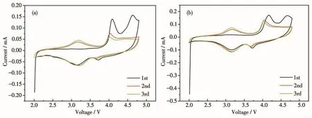
Fig.9 Cyclic voltammograms curves of(a)LFMO and(b)LFMO-2% PPy composites measured at room temperature at 0.1 mV·s-1
To further investigate the effect of PPy on the charge transfer characteristics of LFMO-2% PPy composites,EIS were measured for LFMO and LFMO-2% PPy at the charged state of 4.6 V after 50 chargedischarge cycles at room temperature.Then,the corresponding Nyquist plots and the simplified equivalent circuit model were obtained and are shown in Fig.10.The intercept of the semicircle at the highest frequency with the horizontal axis refers to uncompensated ohmic resistance(RΩ),the high-frequency region of the semicircle represents the migration of the Li+ions at the electrode/electrolyte interface through the solid electro-lyte interphase(SEI)layer(Rs)and the middle frequency of the semicircle denotes the charge transfer resistance(Rct).The low-frequency region of the slope is due to the diffusion of the Li+ion in the bulk material(ZW).CPEsand CPEct(constant phase angle element)refer to the double-layer capacitance of SEI layer and charge transfer,respectively.The total resistance of the electrode(Rtotal)includes theRsandRctcontributions that reflect the kinetics of electrode reaction and the electrochemical stability[35].The Nyquist plots of the PPy-coated electrodes compared with the LFMO material are shown in Fig.10a.It is clearly observed from the data presented in Table 3 that theRctvalues of the LFMO-2% PPy composite were lower than that of the pristine LFMO sample(42.7 vs 110.8 Ω).This is mainly attributed to the improvement in the electrical conductivity of the PPy layer and reduction in theRctrelative to that of the pristine LFMO.These results indicate that the PPy layer can accelerate the electron transfer by the LFMO.
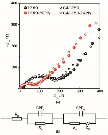
Fig.10 (a)EIS spectra of the LFMO and LFMO-2% PPy at charged state of 4.6 V after 50 cycles;(b)Equivalent circuit for the EIS measurement

Table 3 Simulated results of the LFMO and LFMO-2% PPy
3 Conclusions
LFMO materials coated with conducting polypyrrole have been successfully synthesized by a simple chemical oxidation polymerization method.The coated material showed an initial discharge capacity of 206 mAh·g-1at 1C while the initial coulombic efficiency increased from 57% to 87% upon PPy coating.The LFMO-2% PPy sample exhibited high capacity stability with capacity values of 131 and 139 mAh·g-1at 1C and 2C,respectively.Thus,it is found that the PPy coating effectively improves the electrochemical performance of the LFMO cathode material.The initial irreversible capacity loss was reduced and the cycling capability was greatly improved by PPy modification,most likely due to the accelerated activation of the Li2MnO3during the coating process and the enhanced conductivity of the LFMO electrode conductive layer provided by the PPy modification.
- 无机化学学报的其它文章
- Synthesis and Characterization of Metal-Organic Framework Based on 2,6-Bis(4-carboxybenzylidene)cyclohexanone
- Two Metal-Organic Frameworks Built from 2,2′-Dimethyl-4,4′-biphenyldicarboxylic Acid
- Three Photochromic Co-crystals Based on Viologen Moiety
- Effect of Mass Ratio of Ni and Co in Initial Solution on Oxygen Evolution Reaction Performance of Ni-Co-S-O/NF Catalyst in Alkaline Water Electrolysis
- Structure and Fluorescence Properties of Three 1D/2D/3D Zn/Cocomplexes Based on Flexible Tetracarboxylic Acid
- Two Nitronyl Nitroxide Biradical-Bridged Lanthanide One-Dimensional Chains:Crystal Structure,Magnetic Properties and Luminescent Behavior