Adaptive Backstepping Control Design for Semi-Active Suspension of Half-Vehicle With Magnetorheological Damper
Khalid El Majdoub, Fouad Giri, and Fatima-Zahra Chaoui
Abstract—This paper investigates the problem of controlling half-vehicle semi-active suspension system involving a magnetorheological (MR) damper. This features a hysteretic behavior that is presently captured through the nonlinear Bouc-Wen model.The control objective is to regulate well the heave and the pitch motions of the chassis despite the road irregularities. The difficulty of the control problem lies in the nonlinearity of the system model, the uncertainty of some of its parameters, and the inaccessibility to measurements of the hysteresis internal state variables. Using Lyapunov control design tools, we design two observers to get online estimates of the hysteresis internal states and a stabilizing adaptive state-feedback regulator. The whole adaptive controller is formally shown to meet the desired control objectives. This theoretical result is confirmed by several simulations demonstrating the supremacy of the latter compared to the skyhook control and passive suspension.
I. INTRODUCTION
AUTOMOTIVE control has become a driving factor in automotive innovation over the last twenty-five years. In order to meet the enhanced requirement for lower fuel consumption, lower exhaust emission, improved safety as well as comfort and convenience function, automotive control had to be applied. Faced with the need to reduce gas emissions,the hybrid vehicle or the electric vehicle is now a credible option [1]-[5], and already commercialized despite the intrinsic constraints associated with dual powering and extra equipment costs.
Vehicle suspension system control aims at ensuring passenger’s safety and comfort by reducing vibrations caused by the onboard engine and the road irregularities [6]-[9].Nowadays, magnetorheological (MR) dampers have become among the most effective means toward the achievement of this objective, due to versatility, low-cost, small-size, high achievable forces. They are constituted of MR fluids that reversibly change their rheological properties in the presence of a varying magnetic field. Then, the fluid force can be acted on by changing the magnetic field amplitude, an action that necessitates low energy. These appealing features explain why MR dampers have found, in recent years, several applications in so various domains such as vibration isolation and damping,earthquake and civil engineering, automotive and vehicle industry [10]-[12].
The complexity of MR dampers dynamics lies in the nonlinearity and the hysteretic nature of the force-velocity relationship [13]. Different, more or less complex, dynamic models have been proposed to capture this relationship[14]-[16]. Most of them are in fact variants of the Bouc-Wen hysteresis model and the LuGre friction model.
For the MR dampers to be used as actuators in half-vehicle semi-active system suspension, they need to be appropriately controlled. To this end, several control approaches have been proposed, ranging from simple on-off control techniques to much more advanced linear and nonlinear control techniques including the optimal control and the linear quadratic control(LQR) technique [17]-[19], linear parameter varying (LPV)technique [20], adaptive backstepping active or semi-active suspension for a half-vehicle or quarter vehicle [21]-[24]. In[25], [26], a skyhook damper control algorithm has been proposed for full-vehicle suspension. A hybrid control technique, combining skyhook control and the Groundhook control, has been proposed in [27]. The disturbance (road profile) was assumed to be not a measurable and predictable signal. The control techniques were based on the on-off switched damping strategy, switching between high and low damping coefficients in order to achieve body comfort or road holding specifications.
Another research direction is that using neural network control [28] and fuzzy logic control [29], which are two techniques that do not require the perfect knowledge of the model, but the expertise of the system is mandatory. Other existing control techniques include H2optimal control [30].Optimal and model predictive controllers were combined in[31] leading to semi-active hybrid controllers switching between different control laws.
A fraction of the existing research activity has been devoted to adaptive control design for vehicle suspension. In [32] an adaptive fault-tolerant control design method was proposed for nonlinear pure-feedback systems (with dead-zone actuators and stochastic failures) and validated by simulation on a quarter-car suspension system. The method is not applicable to the problem studied in this work because the considered half-car suspension system does not fit the required pure-feedback structure, due to the hysteresis dynamics of the rheological actuators. The problem of adaptive (finite time) fault-tolerant control was also investigated in [33] for a class of switched nonlinear systems in the lower-triangular form (under arbitrary switching signals) where the unknown functions were approximated by the radial basis function neural networks (RBFNNs). The proposed method applies to single control input systems but it is not applicable to the present two-input two-output system.Furthermore, it is not judicious to use RBFNNs when the system model is available (even in the presence of parameter uncertainty), which is the case in the present paper.
A common shortcoming of all mentioned control systems is that all system states have been supposed to be accessible to measurements and some only achieved a part of the desired performances. Some works involved switching between different control laws, making complex the formal analysis of the closed-loop performances [28]. Others used fully active suspension actuators [21] which are not yet available on most of today’s vehicles because of their high costs. As a matter of fact, semi-active actuators are generally preferred in vehicle industry applications.
In the light of the above description, it becomes clear that most proposed (model-based) control methods for semi-active suspension have based on linear or LPV models. The point is that these models are approximate representations limiting the achievable performances.
The present paper constitutes a significant progress with respect to the existing works because the control design is presently based on a model that accounts for the system nonlinearity, the model parameter uncertainty, and the hysteretic nature of MR damper dynamics. The dynamics of nonlinearity and hysteresis have been captured using the Bouc-Wen model. The Bouc-Wen model is more accurate, but more complex, than the Dahl model. Of course, more complex hysteresis models could be considered but the point is that not all models allow the design of controllers using the available nonlinear control design techniques. Therefore, the control design model should be a compromise between model accuracy and complexity. From this viewpoint, Bouc-Wen model is quite convenient and so is presently based upon.
This paper proposes a new (model-based) adaptive backstepping semi-active suspension control for vehicles involving a semi-active component, i.e., MR damper. The aim is to manage the tradeoff between conflicting requirements, i.e.,ride comfort and driving safety. On the other hand, stabilizing the attitude of the vehicle in the presence of parameter uncertainties is a principal requirement, where suspension spaces and dynamic tire loads are considered to be guaranteed within their allowable ranges. The complexity of the considered control problem is threefold: i) the involved MR dampers dynamics are nonlinear and hysteretic; ii) the state variables associated to MR dampers hysteresis are not accessible to measurements; iii) some parameters of the overall half-vehicle system are uncertain. The control problem is dealt with using the adaptive backstepping design technique and Lyapunov analysis tools [34], [35]. The control design is based on the complete system model that accounts not only for the linear halfvehicle vertical motion but also for angular movement and the hysteretic behavior of the semi-active MR dampers. The adaptive controller includes three main parts: i) state observers providing online estimates of the damper internal state variables; ii) a parameter adaptive law providing online estimates of the uncertain parameters; iii) a nonlinear control law ensuring stability and regulation of the bouncing and pitching motions. The adaptive controller thus constructed is formally shown to meet its objectives.
The paper is organized as follows: Section II is devoted to the modeling of the half-vehicle suspension system with MR damper; the controller design is presented in Section III; the controller performances are illustrated by numerical simulation in Section IV. To alleviate the paper body, some technical parts are placed in Appendices.
II. NONLINEAR HALF-VEHICLE MODEL AND SEMI-ACTIVE COMPONENT MODELING
A. Half-Vehicle Model
Vehicle suspension systems are mainly composed of springs and dampers that filter effort transmission between the vehicle body and the road. Driving safety is the consequence of a harmonious suspension design in terms of wheels suspension,springing, steering, and braking. The driving comfort is closely related to the vibration level: the lower vehicle vibration level causes the better driving comfort quality.Considering the vehicle’s symmetry, the study can be dealt with based on the so-called half-vehicle model shown in Fig.1.This model is characterized by the sprung mass msand the unsprung masses for the front and rear axles mus1and mus2,respectively. As the damping coefficient is negligible, the front and rear tires are simply modeled by springs kus1and kus2linked to the road contact points zr1and zr2.

Fig.1. Model of half vehicle with MR dampers.
The passive suspension between chassis and the front, and rear axles is modeled by two dampers Cs1, Cs2(linearized viscous damping coefficients for the front and rear dampers)and two springs ks1, ks2(spring stiffness for the front and rear dampers). The non-linear half-vehicle model used in this study has four Degree of Freedom due to the heave and pitch motions of the sprung mass and the vertical motions of the unsprung masses. In this model, J stands for the mass moment of inertia for the pitch motion. For the vehicle body, zsand θ represent the heave and pitch motions, respectively. zs1and zs2are the displacements for the front and rear corners of the chassis vehicle, respectively. zus1and zus2are the unsprung masses displacements for the front and rear axles,respectively. In Fig.1, a and b show the distances of the suspensions to the center of the vehicle body and ϑ is the velocity of the vehicle.
The numerical values of the vehicle parameters are given in Table I. Analytically, the nonlinear passive model based upon later, is defined by the following equation:
Bouncing movement:

Pitching movement:

Vertical front and rear axles movements:


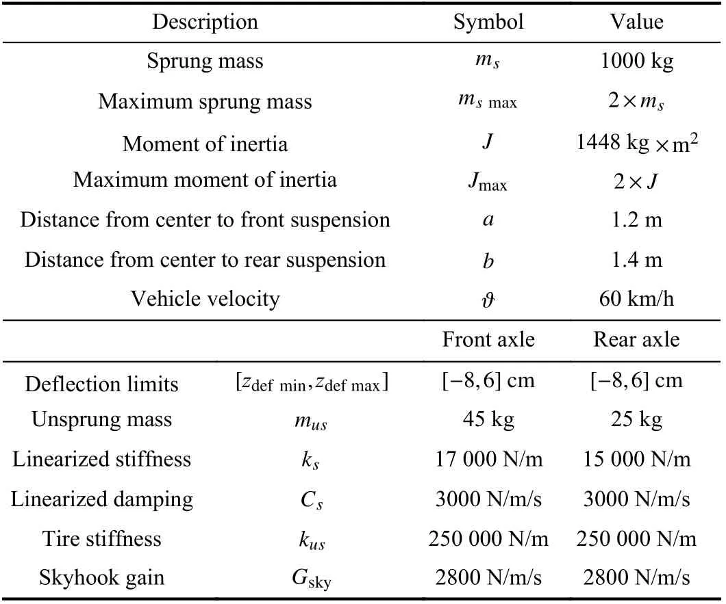
TABLE I PARAMETER NUMERICAL VALUES OF THE HALF-VEHICLE MODEL
B. MR Damper Modeling
Presently, the Bouc-Wen model is retained because it represents a good accuracy/complexity ratio.
Fig.2 illustrates how the hysteresis effect in MR dampers is captured using this model. Analytically, the Bouc-Wen model consists of the following couple of equations for the front and rear dampers, indexed by ( i=1,2), respectively:

where the different notations are defined as follows: ωiis the internal state variable, viis the input voltage, ko1,ko2are the linear spring stiffness, αa1, αa2are the stiffness of ωi, αbiis the stiffness of ωiinfluenced by vi, Coaiis the viscous damping coefficient, Cobiis the viscous damping coefficient influenced by viand ρi, βi, -λiare the positive parameters characterizing the shape and size of hysteresis loop.

Fig.2. Bouc-Wen model for MR damper.
The Bouc-Wen model internal state variable ωiis not accessible to measurements but is formally proved to be bounded. In effect, it is shown in [36], if

Then, the signal ωiremains bounded as follows:

C. Half-Vehicle With MR Damper Model
For convenience, the following vector state is introduced:

where x1and x2are the vertical position and bouncing velocity of the centre of the gravity of the vehicle,respectively. x3and x4denote the pitch position and pitch velocity of the vehicle, respectively. On the other hand, x5, x6and x7, x8denote the vertical displacements and vertical speeds for the front and rear unsprung masses, respectively. In coherence with the notations (6), the state variables of the Bouc-Wen models are denoted: x9=ω1, x10=ω2. Let us introduce the novel notation for the MR damper forces,ui=Fmri. Then, the whole controlled system, including the motion equations (1a-d) and the damper equations (3) and (4),turns out to be described by the following state-space model:


The parameters ki(i=1,10) and hi(i=1,8) are defined in Table II.
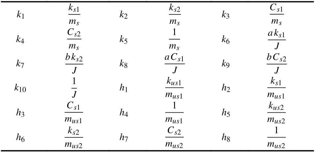
TABLE II THE PARAMETERS k i(i=1,10) AND hi(i=1,8)
In (7k-l), the control inputs are v1and v2. Observe that they are multiplied by states that are not accessible to measurements, namely x9for v1and x10for v2. It is assumed that all state variables x1to x8are accessible to measurements,except for the damper states x9and x10.
In the system suspension with parametric uncertainty there are two types of nonlinearities. The first is smooth nonlinearity introduced by the trigonometric functions and the second is the Bouc-Wen hysteresis nonlinearity introduced by the MR damper actuator. Interestingly, the parameters kiare not required to be exactly known. This is coherent with the fact that the physical quantities ms,J,ks1,ks2,Cs1, and Cs2are likely to change with the operation conditions. It is only required that

where the lower and upper bounds (k5min,k5max,k10min,k10max)are supposed to be a priori known. This assumption is a realistic one since k5and k10are related to the chassis mass and inertia respectively, whose variation ranges are a priori known for each given car. From Table I, one gets that k5min=1/msmaxand k10min=1/Jmax. In (7f-h), the parameters hi(i=1,8) are exactly known. All the parameters in hysteresis Bouc-Wen model are exactly known in (7i-l).
III. ADAPTIVE CONTROL DESIGN
A. Control Objectives
Consider a half-vehicle equipped by two MR dampers (Fig.1)and described by (7) and (8). We seek a controller that meets the following objective.
1) Bouncing and Pitching Regulation: The bouncing and pitching positions x1and x3must track their reference values,denoted x1refand x3ref, presently supposed to be constant. The road contact point zr1and zr2are considered to be known bounded external disturbance.
2) Ride Comfort: The vertical acceleration of the car body must be limited and improved using the considered controller within an admissible range.
3) Good Road Holding: The dynamic tires loads should not exceed the static ones for both of the front and rear wheels[21], i.e.,

where the static tire loads Fi(i=1,2) are given by

4) Suspension Space Limits: Because of the mechanical structure (front and rear axles), the suspension spaces should not exceed the allowable maxima, i.e.,

B. Controller Design
The controller design is performed in two stages. The first stage is relatively short and will consist in designing an observer structure providing estimates of the hysteresis internal variables x9and x10. Then, the second stage will be devoted to designing an adaptive regulator that meets the control objectives of Section III-A.
1) Observer Structure of the Damper Internal States
The internal states x9and x10are not accessible to measurements. To get online estimates of these variables, the following observer structure, suggested by (7i-l), is considered

In the above observer structure, the observation of the state variables x9and x10relies on the measurements of signals u1and u2. Since these signals enter the sub-model (7i-l) through multiplication by the quantities ( αa1+αb1v1) and ( αa2+αb2v2),it follows that observability of the sub-model (7i-l) is only ensured unless the mentioned quantities remain away from zero. Therefore, we make the following observability assumptions:

An observer analysis will be performed later as a part of the whole adaptive controller analysis. In particular, the way the observer gains should be online tuned will be determined bearing in mind the achievement of the output-reference tracking objective. To prepare that analysis, introduce the following observation errors:

Then, it is readily seen, subtracting side-to-side (13a-d)from (7i-j), that the observation errors undergo the following equations:
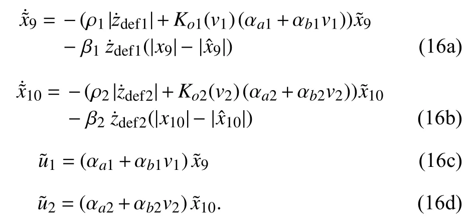
2) Adaptive Backstepping Controller Design
We seek a bouncing-pitching position regulator that enforces the following position errors to asymptotically vanish, whatever the initial conditions:

x1refand x3refdenote the bouncing and pitching position reference values supposed to be constant.

To compensate for parameter uncertainty, the position regulator will be provided with a parameter adaptation capability. To this end, introduce the following notations:

The control law, the parameter adaptation law and the observer gain will now be designed on the basis of (7a-d),using the backstepping technique [35]. This is performed in three steps. For convenience, the following new compact form of the system (7a-d) is introduced:

Design Step 1 (Stabilization Function Design for Subsystem(18a) and (18c)):
Consider the following Lyapunov function candidate for the subsystem (18a) and (18c):

The corresponding time-derivative is

In (18a) and (18c), the variables x2and x4stands for the virtual control signals. Let α1and α3denote the corresponding stabilization functions. Equation (20) suggests that


with this notation, (20) and (22a-b) can be rewritten as

Design Step 2 (Control Law Design for the System (18b)and (18d)):
From (22a-b) it follows, using (23a-b), (18b), and (18d),that the errors e2and e4undergoe the following equations:

Consider the Lyapunov function candidate

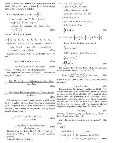

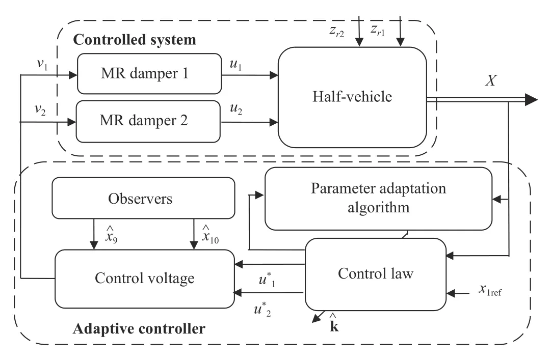
Fig.3. Vehicle suspension adaptive backstepping control.

TABLE IV THE NUMERICAL VALUES OF THE MR DAMPERS PARAMETERS
As a semi-active control approach, the skyhook control strategy supposes that the sprung body is connected to a virtual sky by a damper [25]. The front and rear dampers are indexed by (i=1,2), respectively. The skyhook control law is mathematically described by


The passive suspension is a simpler variant of the damping force described by (3).

where the index “p” refers to “passive”. The parameters Coaiand koi( i=1,2) are given in Table IV.
The root mean square (RMS) value of the vehicle body acceleration is often used as a measure of passenger drive comfort. That is, the vertical acceleration RMS is considered in this study to evaluate the quality of ride comfort. Recall that the RMS value of an n-dimensional vector x is defined as follows:

where ‖·‖ denotes the usual Euclidian norm. The acceleration peak value is also of some interest. It refers to the maximal magnitude of vehicle body or passenger acceleration. The peak value is

where ‖ ·‖∞denotes the infinity norm.
The static tire loads for both front and rear wheels can be calculated by (11a-b) as F1=5718N and F2=4768N.
The control design parameters are given the values c1=1,c2=0.01, c3=1, c4=0.01, δ1=0.01, δ2=0.01, γ=1,λo1=10, and λo2=10, which proved to be suitable.
A. Time Domain Analysis With Deterministic Road
The vehicle speed produces an effect on the performances of the half vehicle suspension model. Indeed, the speed determines the frequency of the disturbances caused by road irregularities which in turn affect the suspension frequency behavior. Two considered road profiles are referred to bump road input and road input with limited ramp. The input zr2for the rear wheels is the same as that for the front ones but delayed by a certain time τ =(a+b)/ϑ.
Bump Road Input: This profile is the most encountered in practice; it is analytically described by

where hb=4 cm represents the height of the bump road input,T1=1s and T2=2s. This profile is shown by Fig.4 and the system responses, obtained with the proposed semi-active control and with the passive suspension, are plotted in Figs. 5(a)(chassis heave displacement) and 5(b) (heavy acceleration),Figs. 6(a) (pitch motion) and 6(b) (pitch acceleration).

Fig.4. The bump road inputs.
The variation of the front damper force is shown in Fig.7(a),and the rear damper force is plotted in Fig.7(b). It is seen from Figs. 5(a), 5(b) and 6(a), 6(b) that the amplitude for the vertical position, the pitch motion, the bouncing acceleration and the pitch acceleration vanish much faster with the semiactive suspension control than with skyhook control and passive suspension. To quantify the ride comfort improvement, the RMS values for the vertical acceleration of the vehicle body are computed using (41). The RMS values for the bouncing and pitch accelerations of the vehicle body are presented in Table V. It is seen that these values are greatly reduced with the adaptive controller resulting in improved ride comfort.

Fig.5. (a) The heave of the sprung mass for the bump road; (b) The heave acceleration of the sprung mass for the bump road.

Fig.6. (a) The pitch of the sprung mass for the bump road; (b) The pitch acceleration of the sprung mass for the bump road.
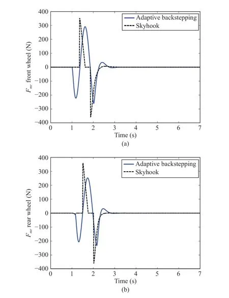
Fig.7. (a) The front damper force for the bump road; (b) The rear damper force for the bump road.
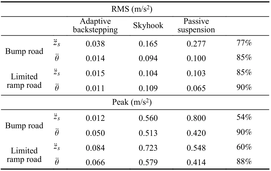
TABLE V COMPARATIVE RESULT BETWEEN DIFFERENT CONTROL LAW
The decrease in the RMS values is 77% for the bouncing acceleration and 95% for the pitch acceleration.
The comparison between suspensions techniques can also be checked by analyzing the peak values (42). As seen, the peak values are substantially decreased by the adaptive controller, that is, the maximum accelerations sensed by the passengers are decreased by 54% for the heave acceleration and 90% for the pitch acceleration. This results in increased ride comfort. In the adaptive suspension control, the limitations of the suspension spaces should be taken into account, it can be observed from Figs. 8(a) (front working space) and 8(b) (rear working space) that the controlled suspension spaces are all below the limitations (12). The road holding is computing by (10). Figs. 9(a) (dynamic front tire load) and 9(b) (dynamic rear tire load) show that the dynamic tires loads are all within the bounds.
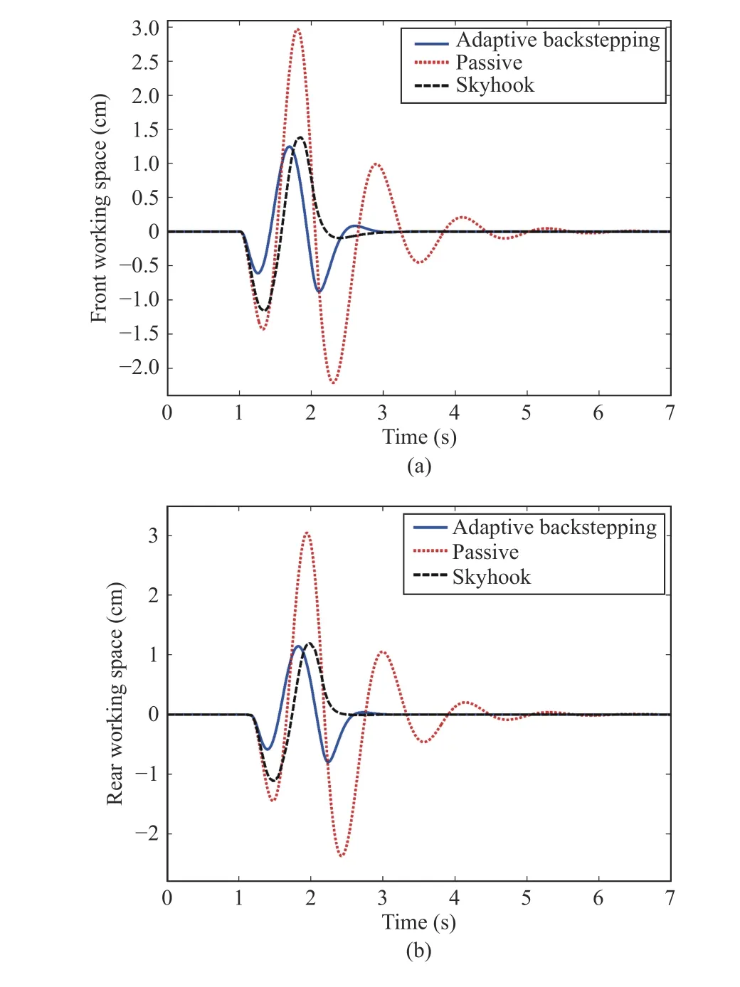
Fig.8. (a) The front working space for the bump road; (b) The rear working space for the bump road.
Limited Ramp: A road with limited ramp, depicted by Fig.10,is considered. Analytically, the road shape is defined as follows, where hr=0.02 m is the final road surface elevation,T1=1s and T2=1.1s:


Fig.9. (a) The dynamic front tire load for the bump road; (b) The dynamic rear tire load for the bump road.

Fig.10. The limited ramp road inputs.
The obtained control performances are illustrated by Figs. 11(a), 11(b), 12(a), and 12(b). These show the halfvehicle body vertical displacement (Fig.11(a)), the vertical acceleration (Fig.11(b)), the pitch motion (Fig.12(a)), and the pitch acceleration (Fig.12(b)). It is seen that the vehicle settles smoothly to the final height value of the road input and the vertical displacement magnitude and acceleration are not large. Let us evaluate the RMS value of the vertical motion acceleration and the pitch acceleration of the sprung mass(Table V). The ride comfort is significantly improved with the adaptive controller; the RMS decreases by 85% for the bouncing acceleration and decreases by 90% in the case of the pitch acceleration. The peak value of the vertical motion acceleration is decreases by 60%. On the other hands, the peak value is decreases by 88% in the case of the pitch acceleration.That is, the decrease is quite significant. The front and rear MR dampers forces produced by adaptive controller, with respect to time are depicted in Figs. 13(a) and 13(b). It is seen from Figs. 14(a) (front working space) and 14(b) (rear working space) that the controlled suspension spaces are respected. The road holding is checked by Figs. 15(a)(dynamic front tire load) and 15(b) (dynamic rear tire load).That shows that the dynamic tires loads are all within the bounds.
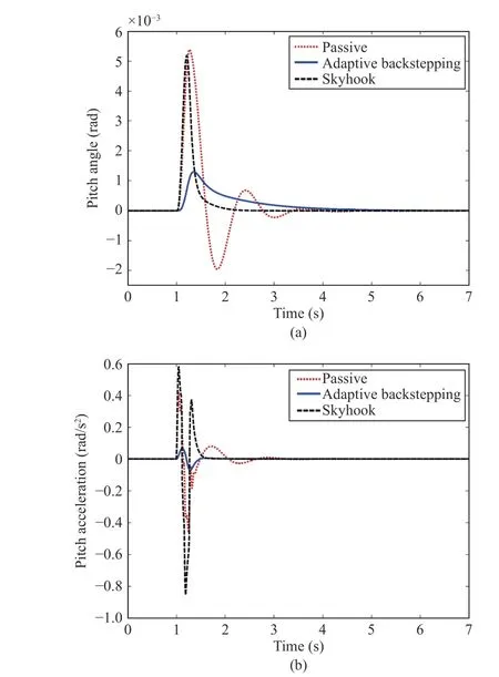
Fig.12. (a) The pitch of the sprung mass for the limited ramp road; (b) The pitch acceleration of the sprung mass for the limited ramp road.

Fig.13. (a) The front damper force for the limited ramp road; (b) The rear damper force for the limited ramp road.
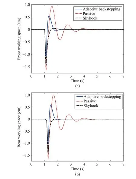
Fig.14. (a) The front working space for the limited ramp road; (b) The rear working space for the limited ramp road.

Fig.15. (a) The dynamic front tire load for the limited ramp road; (b) The dynamic rear tire load for the limited ramp road.
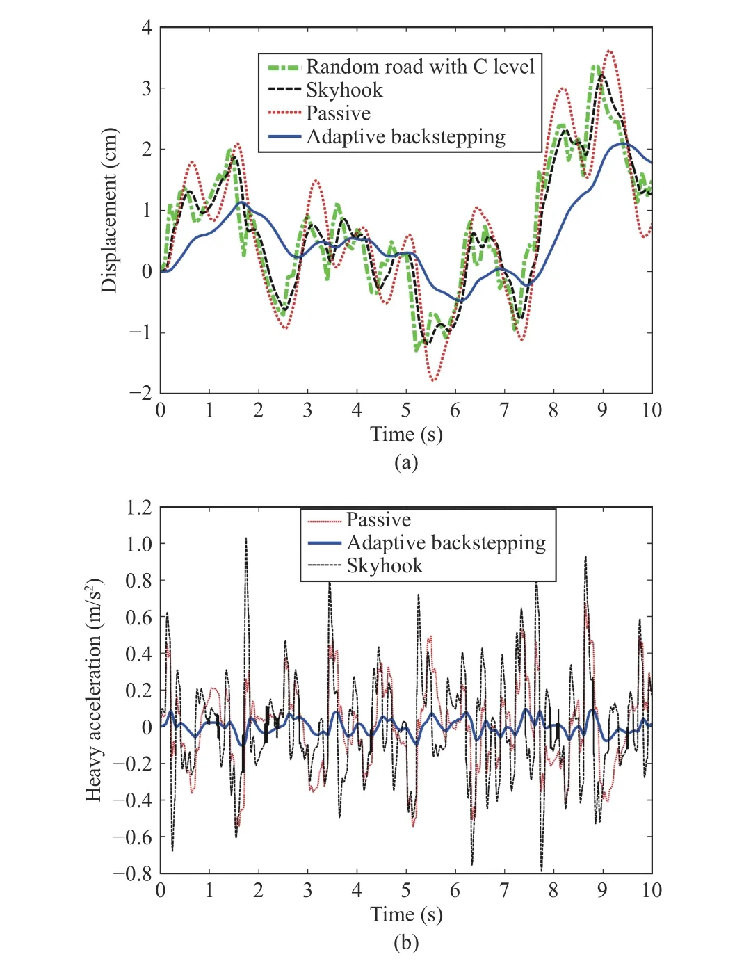
Fig.16. (a) The heave of the sprung mass for the random road; (b) The heave acceleration of the sprung mass for the random road.
B. Time Domain Analysis With Random Road With C Level, ISO 8608
Now, a random road profile is considered to illustrate the validity and effectiveness of the presently proposed controller.In this test, a zero reference is considered, i.e., zsref=0.Random road profile is generated by linear filtering methods and harmonic superposition method [38]. The main idea is to generate random number road profile with road class roughness-C according to the inter-national standard organization (ISO) 8608. The equation of the random road profile is as follows:

where f0=0.011 Hz stands for the offline cutoff frequency, zriis the road roughness amplitude, ϖ is a white noise whose intensity is 1, ϑ is the vehicle speed, n0is the frequency of reference space whose value is 0.1 Hz, G=256×106m3is the road roughness coefficient for road of C level.
The responses of a half vehicle model using adaptive controller, on one hand, and skyhook and passive control to random road excitation, on the other hand, are presented in the subsequent lines. The sprung mass vertical displacement, the bouncing acceleration, the pitch motion and the pitch acceleration are plotted in Figs. 16(a), 16(b), 17(a), and 17(b),respectively. It is seen that the magnitudes of the heave, pitch and corresponding accelerations are significantly decreased with the adaptive controller, confirming the efficiency of the latter in the presence of known road. The decreases in the RMS values of the heave and pitch accelerations (of the vehicle body) are 80% and 95%, respectively. Such large decrease of RMS values entails an improved ride comfort. In turn, the Peak values for the heave and pitch accelerations are substantially decreased with the adaptive controller.Specifically, the maximum accelerations sensed by the passengers are decreased by 90% and 97%, respectively,which results in substantially increased ride comfort.
V. CONCLUSION
This paper presents a new approach of controlling the vertical movement of a half car vehicle facing deterministic with a constant velocity. The main component of the proposed suspension system is an adaptive controller designed by the adaptive backstepping technique on the basis of a model that accounts for the hysteresis effect in the MR dampers. The controller consists of two observers estimating the damper hysteresis internal states, a parameter adaptive algorithm estimating the system uncertain parameters and an adaptive state-feedback control law stabilizing the suspension system.The adaptive controller is formally shown to meet its control objectives. This theoretical result is confirmed by several simulations that also illustrate the high supremacy of the semiactive suspension over the passive suspension and the semiactive skyhook suspension. Compared to previous works on semi-active suspension, our solution presents several features:i) this solution involves a new component such as MR dampers modeled by the Bouc-Wen model; ii) it does not assume all system states and all system parameters to be known; iii) it does not involve switching between different control laws; iv) it enjoys a formal closed-loop stability analysis. Finally, it is checked with the simulation study of Section IV that the backstepping adaptive controller involving MR dampers improves a good ride comfort and road holding.
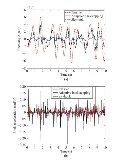
Fig.17. (a) The pitch of the sprung mass for the random road; (b) The pitch acceleration of the sprung mass for the random road.
This study can be continued in many directions, e.g.,designing a higher supervision loop computing online optimal values of the control design parameters; optimality is to be defined in terms of control performances.
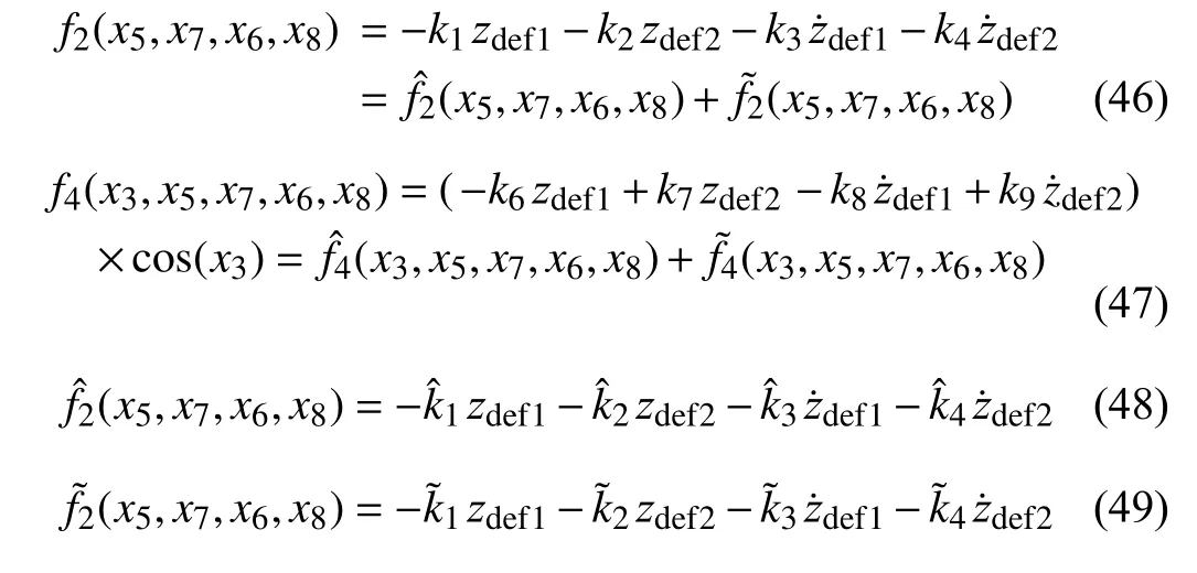
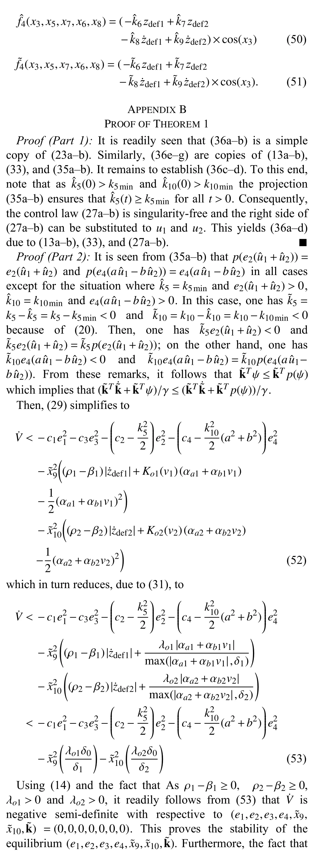
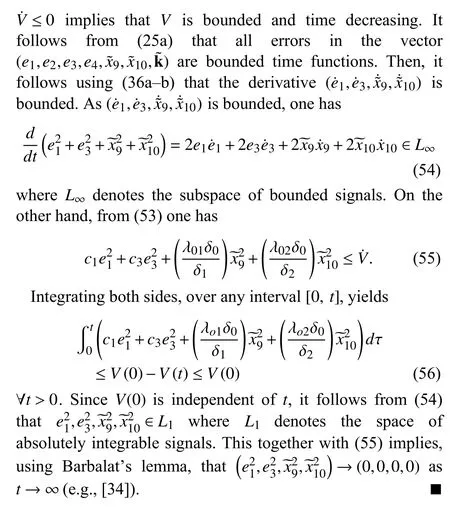
APPENDIX A MODEL AND CONTROLLER PARAMETERS AND FUNCTIONS
 IEEE/CAA Journal of Automatica Sinica2021年3期
- IEEE/CAA Journal of Automatica Sinica的其它文章
- Deep Learning in Sheet Metal Bending With a Novel Theory-Guided Deep Neural Network
- Nonsingular Terminal Sliding Mode Control With Ultra-Local Model and Single Input Interval Type-2 Fuzzy Logic Control for Pitch Control of Wind Turbines
- Deep Learning for EMG-based Human-Machine Interaction: A Review
- Distributed Secondary Control of AC Microgrids With External Disturbances and Directed Communication Topologies: A Full-Order Sliding-Mode Approach
- Autonomous Control Strategy of a Swarm System Under Attack Based on Projected View and Light Transmittance
- Computing Paradigms in Emerging Vehicular Environments: A Review
