Efficient manipulation of terahertz waves by multi-bit coding metasurfaces and further applications of such metasurfaces∗
Yunping Qi(祁云平) Baohe Zhang(张宝和), Jinghui Ding(丁京徽), Ting Zhang(张婷),Xiangxian Wang(王向贤), and Zao Yi(易早)
1College of Physics and Electronic Engineering,Northwest Normal University,Lanzhou 730070,China
2School of Science,Lanzhou University of Technology,Lanzhou 730050,China
3Joint Laboratory for Extreme Conditions Matter Properties,Southwest University of Science and Technology,Mianyang 621900,China
Keywords: coding metasurface, Pancharatnam–Berry phase, multiple beams, radar cross-section (RCS) reduction,orbital angular momentum
1. Introduction
Terahertz (THz) waves, whose frequency range is between 0.1 THz and 10 THz, are on the cutting edge of new technologies and have drawn enormous attention from worldwide academia in recent years,because of their numerous potential applications in biosensing, security imaging, and THz high-speed communications.[1–6]The manipulation of terahertz waves, especially their polarization, phase, and amplitude, is important in terahertz application systems. Unfortunately,most of the conventional materials in nature have great difficulty in achieving effective control of terahertz waves,which limits the development of terahertz technology and applications. Therefore, we need new and innovative ideas to address the lack of natural materials that can be used in the terahertz band.
A metasurface is a two-dimensional planar structure composed of an array of subwavelength units,which provides unprecedented capabilities for the flexible and effective manipulation of the phase,amplitude,polarization,and various other properties of incident electromagnetic waves.[7–17]The arrival of metasurfaces has made up for the shortage of electromagnetic materials in the terahertz band, has provided an effective way to realize functional devices in the terahertz band,and is expected, in essence, to break through the bottleneck of terahertz technology development. To date, many remarkable achievements based on metasurfaces have been accomplished and demonstrated in the microwave band, including high-gain antennas,[18]polarization conversion,[19–21]beam focusing,[22,23]radar cross-section reduction,[24–26]vortexbeam generation,[27–30]and so on. In comparison with the microwave band, terahertz waves are a new research topic,and related technologies are still in the early stages of exploration. More recently, metasurfaces have been extended to the terahertz region and have played an irreplaceable role in the production of novel functionalities,such as near-perfect absorbers,[31–36]super-lenses,[37]holographic imaging,[38,39]and sensing.[40–43]Unfortunately, so far, most of the new achievements with metasurfaces have had problems due to their complex structure,low operating efficiency,and because they can only afford one specific function within a limited frequency range, which is a key challenge for terahertz technology to be able to achieve multiple functionalities.
Digital coding metasurfaces are a significant branch of metasurfaces that create a new bridge between the physical world and digital information science.In this study,to the best of our knowledge,this is the first time that the proposed double E-shaped structure has been combined with the PB phase principle to generate a multi-bit coding metasurface, which shows promise for many important applications in the terahertz range. Using a 1-bit coding metasurface with specific distributions of the coding sequences, the reflected terahertz waves can be flexibly and independently manipulated. To realize a low RCS in the terahertz band, we propose a simple and high-performance reflective metasurface based on 2-bit coding elements, which can achieve a >10 dB RCS reduction within a wideband range from 2.1 THz to 5.2 THz. Apart from the useful functionalities described above, we designed two kinds of reflective metasurfaces based on 3-bit coding elements,which were able to realize orbital angular momentum waves with mode numbers of l=1 and l=2. The simulated results prove that the designed scheme has great potential for future practical application in the terahertz frequency range.
2. Theoretical formulation
To achieve high-efficiency manipulation of incident electromagnetic waves, it is important to obtain 360◦full-phase coverage. In terms of controlling the geometric phase change,the PB phase metasurface exhibits unique advantages,and can simply obtain phase responses,just by a rotation of the metallic pattern’s angle. In what follows,we first theoretically infer the principle of the PB phase. For a double E-shaped unit under the Cartesian coordinate system, when the optical axis is rotated by an angle of θ in the anticlockwise direction,the coefficients of reflection can be characterized by the reflective Jones matrix[44]

in which the diagonal elements Rxxand Ryydenote the copolarized reflection coefficients under the normal incidence of x- and y-polarization, whereas the off-diagonal elements,Rxyand Ryx, denote the cross-polarized reflection coefficients under the normal incidence of x- and y-polarization. In general, for an anisotropic metasurface at an oblique incidence,Rxy/=Ryx. In the case of normal incidence,i.e.,Rxy=Ryx=0,the reflection matrix has the following relationship in the rectangular coordinate system:


By substituting Eq. (2)into Eq. (3),the reflection matrix under the excitation of a circularly polarized wave can be derived as


Our target in this work is to achieve efficient manipulation of terahertz waves,RCS reduction,and OAM generation by appropriate arrangement of the coding sequence. The key step is to achieve a phase shift that covers a broad range of 0◦–360◦while maintaining constant scattering amplitudes. To accomplish our goal,the rotation angle θ of each coding particle is changed from 0◦to 157.5◦in steps of 22.5◦. The corresponding phases of the eight coding particles are 0◦,45◦,90◦,135◦,180◦,225◦,270◦,and 315◦,respectively. Because each coding particle has a specific rotational angle,there is an additional degree of freedom for manipulating terahertz waves that offers many novel functionalities.
3. Design of the unit and theoretical analysis
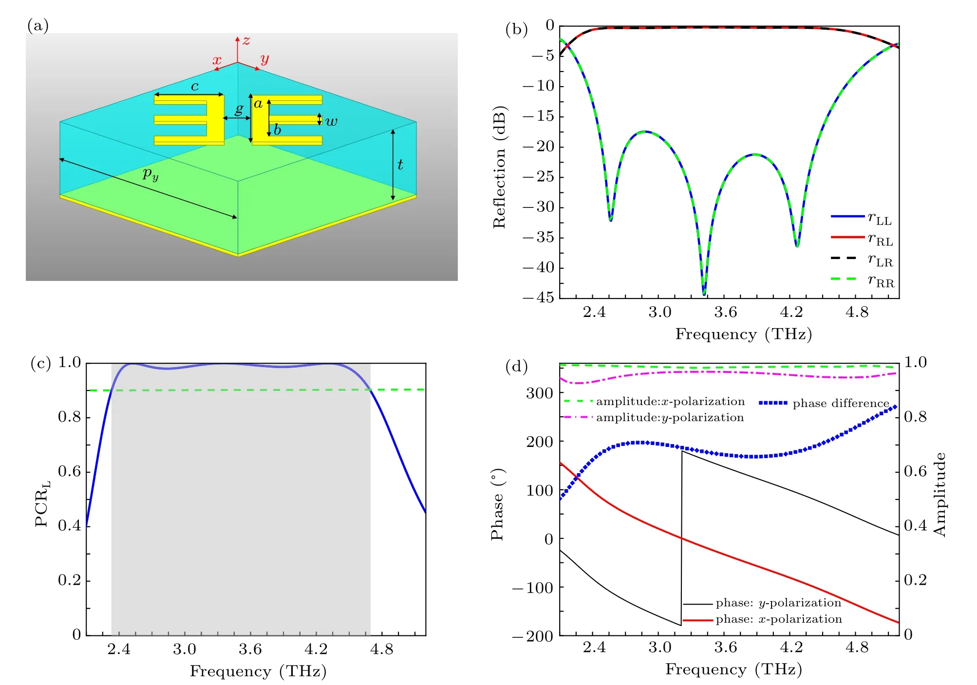
In the design of our PB coding metasurface,the basic coding particle unit is a classic sandwich structure,which consists of three parts: a top-layer double E-shaped structure,an intermediate dielectric layer, and a bottom metal layer, as shown in Fig.1(a). The double-E structure and the bottom metallic film are made of copper,whose conductivity and thickness are 5.8×10⁷S/m and 240 nm,respectively. Polyimide is adopted as the intermediate dielectric substrate with a thickness of t =11 µm and the relative dielectric constant and loss tangent are εr=3.0 and tanδ =0.001,respectively. The detailed geometric parameters of the coding particle were optimized by simulation software as follows: a=20 µm, b=15 µm,c=10 µm, w=2.5 µm, g=4 µm. The period of the coding particle is px= py= 36 µm. Unit-cell simulation was performed using the finite element method,in which the master and slave boundary conditions were used in the x and y directions and Floquet port excitation was adopted in the −z direction.


Fig.1. (a)Design of the double Eshaped basic coding cell. (b)Simulated co-and cross-polarized reflection coefficients under the normal incidence of LCP and RCP waves. (c)Simulated PCR under LCP wave excitation. (d)Simulated reflected phase and amplitude under the normal incidence of linearly x-and y-polarized waves,respectively.
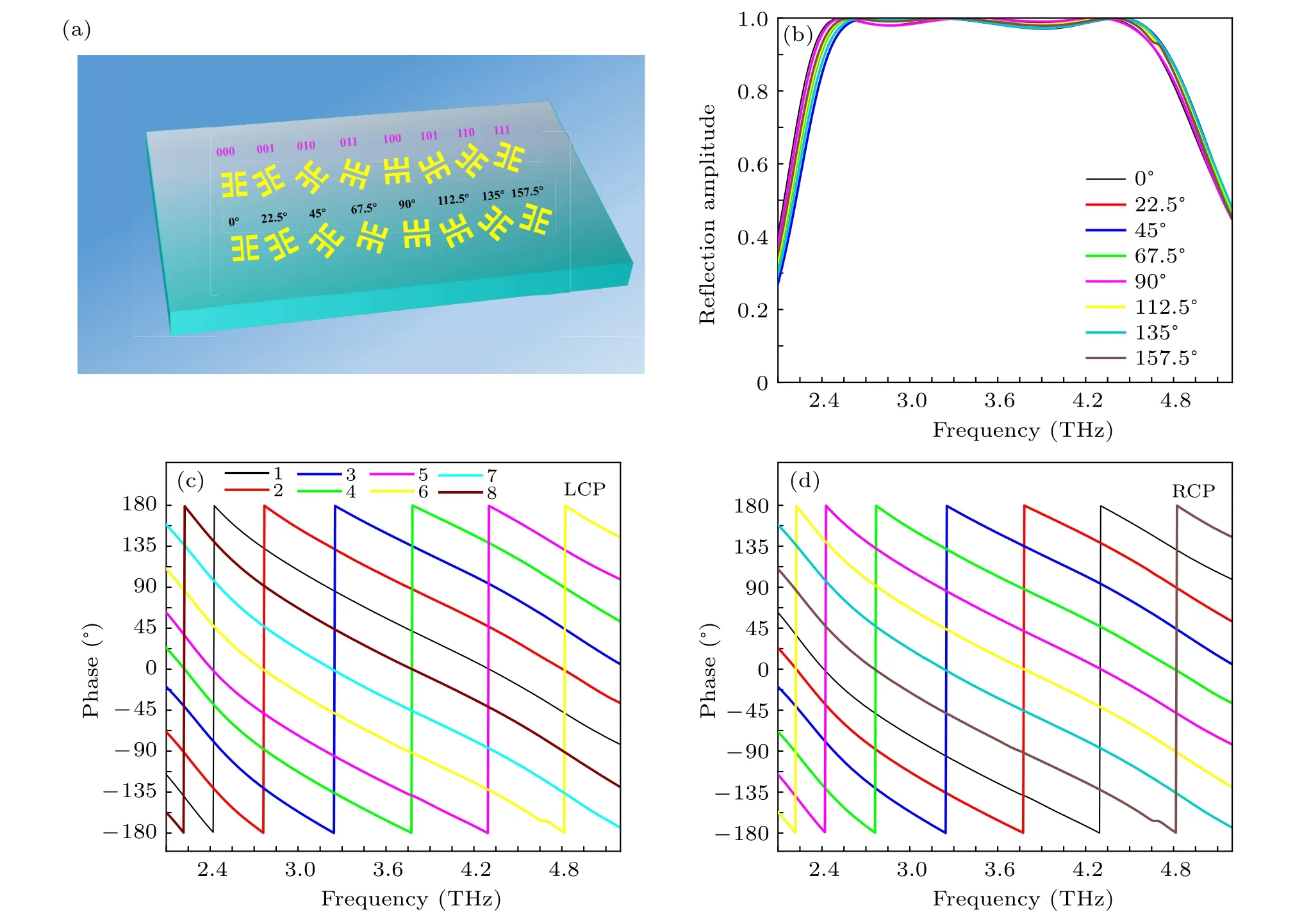
By adopting the concept of the PB phase, the required phase can be more conveniently achieved and the scattering patterns of the coding metasurface can be deflected in a specific direction. Figure 2(a) shows the particles of the 1-bit,2-bit,and 3-bit coding metasurfaces and the corresponding relationship between the particle and the rotation angle.For simplicity,the numbers“0”to“7”represent the bit combinations“000”,“001”,“010”,“011”,“100”,“101”,“110”,and“111”,respectively. Figure 2(b) depicts the magnitude of the reflection response for cross-polarization of eight basic coding particles with different rotational angles under the incidence of LCP or RCP waves. One can find that as the rotation angle θ changes from 0◦to 157.5◦with steps of 22.5◦, the amplitude of the cross-polarization reflection coefficient for eight elements is greater than 90%over a broadband frequency range from 2.4 THz to 4.7 THz. Figures 2(c) and 2(d) show the phase responses of eight basic coding elements under the normal incidence of LCP and RCP waves,respectively.It is worth noting that in the frequency range from 2.1 THz to 5.2 THz,the phase difference between adjacent coding elements always remains at about 45◦,which not only ensures that our design of PB coding metasurface can work over a wide frequency range but also proves the corresponding relationship between the reflection’s phase difference and unit cell’s rotational angle is±2θ,where“+”corresponds to LCP wave incidence and“−”corresponds to RCP wave incidence.

Fig.2. (a) The design of the coding elements for 1-, 2-, and 3-bit coding metasurfaces. (b) The corresponding reflected amplitude of crosspolarization with different rotation angles. The simulated reflection phase responses of the basic element with different rotation angles for(c)LCP and(d)RCP incidences.
By designing appropriate coding sequences, the multibit coding metasurface provides new opportunities for the effective manipulation of terahertz-wave scattering patterns and may offer widespread applications. In the next sections, we will give a few examples to illustrate that multi-bit coding metasurfaces have the ability to achieve highly efficient manipulation of terahertz waves and that they can implement different functions.
3.1. The 1-bit coding metasurface
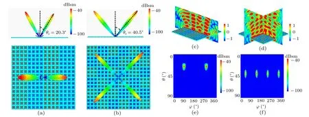
For a 1-bit coding metasurface,the basic coding elements are composed of two digital states,“0”and“1”,and their corresponding reflection phases are 0◦and 180◦, respectively. It is well known that lots of interesting physical phenomena of electromagnetic regulation mechanisms can be generated by arranging specific coding sequences. In other words, we can control the scattering characteristics of coding metasurfaces by changing the corresponding“0”and“1”coding sequences.As an example,two kinds of 1-bit coding metasurfaces are employed with different coding sequences to verify that the coding metasurface has properties that can control far-field scattering patterns more freely. For the 1-bit coding metasurface M1,the simulated three-dimensional scattering patterns under the normal incidence of an LCP wave at 3 THz are shown in Fig.3(a). It should be noted that when the coding sequences“00001111···” of the metasurface M1are arranged in the xaxis direction, two symmetrical main beams with angles of θr=20.3◦are generated. According to a generalization of Snell’s law, the anomalous reflection angle for normal incidence can be predicted by the following equation:[46]

in which λ is the free-space wavelength of the incident wave at 3 THz and Γ =4×144µm represents the period of the coding sequence. Similarly,we also design the M2coding metasurface with the ”010101···/101010···” coding sequence, as displayed in Fig.3(b). In this case, each lattice consists of 3×3 units of the same”0”or”1”coding elements. It can be observed that the scattered energy for a normally incident LCP wave at 3 THz is equally split into four symmetrical oblique beams with the same elevation angle. The elevation angle θ and the azimuthal angle ϕ of the four oblique beams can be predicted by the following equations:[47,48]

in which θ1and θ2are the beam deviation angles corresponding to the two periodic coding sequences that vary along the x and y directions, respectively. Under such conditions, θ1and θ2as calculated by Eq. (5) are both 27.6◦, and thus, the new beam deviation angle is calculated to be 40.5◦. The azimuthal angles ϕ of the four oblique beams are 45◦, 135◦, 225◦, and 315◦, respectively. The numerical simulation and theoretical calculation are in excellent agreement, which proves the outstanding performance of the proposed schemes. To further verify this interesting phenomenon,the near-field distributions of the two proposed coding metasurfaces are analyzed,as depicted in Figs.3(c)and 3(d). In addition,the two-dimensional scattering patterns are also studied,as illustrated in Figs.3(e)and 3(f). The above research results demonstrate that our designed coding metasurface has good performance when used to manipulate the energy of the main lobe of normally incident terahertz waves,which can be used to realize many interesting applications such as terahertz beam splitters.

Fig.3. The simulated 3D and 2D far-field scattering patterns of the 1-bit coding metasurface. (a), (c), (e) The far-field scattering pattern and near-field energy distributions of the 00001111··· sequence at 3 THz. (b),(d),(f)The far-field scattering pattern and near-field energy distributions of the 010101···/101010··· sequence at 3 THz.
3.2. The 2-bit coding metasurface


Fig.4. Schematic diagram of a 2-bit coding metasurface. (a) 8×8 coding sequences. (b) Ms1 coding array. (c) Simulated 3D scattering patterns of Ms1 under normally incident plane wave excitation at 4 THz. (d) Simulated monostatic RCSs of Ms1 and a metal plate at 4 THz for ϕ =0. (e) The monostatic RCS reduction curves for Ms1 and the equal-sized metal plate under normally incident x-and y-polarized waves.
3.3. The 3-bit coding metasurface
In this section,similarly to the design methods mentioned above for the 1-bit and 2-bit coding metasurfaces, we further introduce a 3-bit coding metasurface,whose basic digital elements are“1”,“2”,“3”,“4”,“5”,“6”,“7”,“8”,corresponding to phase responses of 0◦,45◦,90◦,135◦,180◦,225◦,270◦,and 315◦, respectively, which can provide more abundant phases to manipulate terahertz waves. To demonstrate the versatility of the 3-bit coding metasurface for terahertz modulation,two different reflective metasurfaces are employed to generate terahertz vortex beams under the illumination of plane terahertz waves at 3 THz. The numerical calculation is performed by the finite-element method. A typical characteristic of a vortex beam is that it has a spatially distributed spiral phase term eilϕ, where l denotes the designed OAM mode number, also known as the number of topological changes, and ϕ denotes the azimuthal angle.[50–52]The overall size of the two designed reflective metasurfaces is set to 720×720µm2,and they consist of an array of 20×20 cells. For the OAM mode l=1,the metasurface consists of eight sectors,and the phase gradient increment between adjacent sectors is 45◦, as shown in Fig.5(a). For the OAM mode l=2,the metasurface also consists of eight sectors, and the phase gradient increment between adjacent sectors is 90◦, as shown in Fig.5(e).Figures 5(b),5(f)and 5(c),5(g)give the simulated results and schematic diagrams of the vortex intensity and phase distribution of l =1 and l =2, respectively. As can be seen from Figs.5(b)and 5(f),the center point of the light field is a dark field, in other words, the intensity at the vortex’s center is zero. As can be seen from the near-field phase distribution of Figs. 5(c) and 5(g), for the l =1 mode, the wave-front’s phase exhibits a single spiral state; for the l =2 mode, the wave-front’s phase exhibits a double spiral state. It is worth noting that the rotational center of the phase distribution of the vortex beam is slightly separated, which is caused by the discontinuity of the array’s arrangement. The simulated 3D far-field scattering patterns of OAM vortex beams with mode numbers l=1 and l=2 are shown in Figs.5(d)and 5(h). In addition, the two-dimensional scattering patterns corresponding to the two modes in the radar coordinate system and the Cartesian coordinate system are shown in Figs. 5(i) and 5(j).The above simulation results reveal that the vortex beam with orbital angular momentum is produced using the proposed reflective metasurface, which proves that our design has great potential for next generation ultra-high-speed wireless communication systems.

Fig.5. (a),(e)A schematic diagram of the digital phase distribution used to generate OAM vortex beams with topological charges of l=1 and l=2.(b),(f)The simulated amplitude distributions. (c),(g)The simulated near-field phasedistribution diagram. (d),(h)The simulated 3D far-field scattering patterns. (i),(j)The 2D scattering patterns of the two modes l=1 and l=2.
Finally, although this article is a theoretical and simulative work, and not experimental, the fabrication of coding metasurfaces and experimental demonstration is to be expected: the proposed coding metasurface sample can be manufactured by standard photolithography techniques, electronbeam evaporation equipment,and a lift-off process. The production process is as follows:firstly,a copper film is deposited onto a polyimide film by an electron-beam evaporation coating machine,then a homogenizer is used to evenly apply photoresist to the surface of the sample to be etched. Next,choosing the appropriate temperature and baking time is very important,because the photoresist film can be fully dried after baking the photoresist-spin-coated sample. Secondly,a lift-off process is used to form the metasurface pattern on top of the polyimide layer. Thirdly, the sample is immersed in acetone to remove any excess photoresist. Finally, the sample can be measured by a terahertz time-domain spectroscopic test system.
4. Conclusions
In summary, we have successfully proposed 1-bit, 2-bit,and 3-bit reflection coding metasurfaces to manipulate electromagnetic scattering and radiation and to implement different functions,respectively. In our study of the 1-bit coding metasurface,by designing appropriate coding sequences we found that the reflected terahertz wave can be split into two or four main beams, which can be used to realize beam splitting and beam scanning.For RCS-reducing applications,a 2-bit coding metasurface was elaborately designed,which was able to scatter the reflected terahertz energy in more directions. The simulation results showed that the proposed metasurface achieved a>10 dB RCS reduction over a wide frequency band ranging from 2.1 THz to 5.2 THz. In addition, we designed two different kinds of 3-bit coding metasurface for generating multimode OAM beams. The proposed metasurfaces offers new possibilities for terahertz wave control and pave the way for the development of novel functionalities in the future.
- Chinese Physics B的其它文章
- Statistical potentials for 3D structure evaluation:From proteins to RNAs∗
- Identification of denatured and normal biological tissues based on compressed sensing and refined composite multi-scale fuzzy entropy during high intensity focused ultrasound treatment∗
- Folding nucleus and unfolding dynamics of protein 2GB1∗
- Quantitative coherence analysis of dual phase grating x-ray interferometry with source grating∗
- An electromagnetic view of relay time in propagation of neural signals∗
- Negative photoconductivity in low-dimensional materials∗

