Numerical simulation of impact of supersonic molecular beam injection on edge localized modes
Yuanzhen WANG (王元震) , Tianyang XIA (夏天阳) and Yue LIU (刘悦)
1 Key Laboratory of Materials Modification by Laser, Ion and Electron Beams (Ministry of Education),School of Physics, Dalian University of Technology, Dalian 116024, People’s Republic of China
2 Institute of Plasma Physics, Chinese Academy of Sciences, Hefei 230031, People’s Republic of China
Abstract
Keywords: BOUT++ code, SMBI, P-B mode, ELM, ELM size
1.Introduction
The high confinement mode (H-mode) [1] is a promising operational regime for existing and future tokamaks including the International Thermonuclear Experimental Reactor (ITER) [2].During an H-mode discharge, a transport barrier with large pressure gradient close to the plasma edge is formed.As a result,a‘pedestal’is built in the outer region of the pressure profile [3].Turbulence and transport processes are suppressed in the pedestal, which may be due to theE×Bshear flow [4, 5].Because of magneto-hydrodynamic instabilities, the pedestal collapses periodically releasing particles and energy to the outside known as edge localized modes(ELMs)[6].In experiments,the eruption of filamentary structures from the plasma edge is observed during ELMs [7].In theoretical researches,ELMs are explained by the theory of peeling-ballooning (PB)mode[8].Some codes such as ELITE[9]and BOUT++[10] can simulate P-B modes.The ELITE code is mainly used for linear simulations.The three-field [11], five-field[12]and six-field[13]modules in the BOUT++framework can perform not only linear, but nonlinear simulations including the effects of diamagnetic drift,E×Bdrift,resistivity and hyper-resistivity [14].
ELMs may cause unacceptable erosion of plasma-facing components (PFCs) [15].In order to ease the ELM erosion problem, methods have been developed to reduce the ELM size and mitigate the impact of ELMs,such as pellet injection[16, 17], lower hybrid current drive [18], resonant magnetic perturbation [19, 20], impurity injection [21, 22] and supersonic molecular beam injection(SMBI)[23].In this work,the impact of SMBI on ELMs is studied.SMBI is a fuel injection method of tokamaks [24].It is found that the ELM size decreases and the frequency of ELMs increases after the deposition of SMBI [23].Moreover, a recent research shows that seeding mixed gas is more efficient [25].The physics of the ELM mitigation phenomena by SMBI is poorly understood.Rhee et al used a cellular automata model to simulate the ELM mitigation by SMBI, and they believe that shallow SMBI deposition is sufficient for ELM mitigation [26].Huang et al added source terms to the five-field module of BOUT++ framework, and also did some simulation researches about this [27, 28].Their results show that adding particle sources at different locations of the pedestal has different impacts on ELMs.Experimental results show that SMBI reduces the ion temperature in the pedestal, while the ELM size is reduced[29].We think that the low-speed ions seeded by SMBI cool the ions in the pedestal by Coulomb collisions with them [30], so that the ELM size is reduced at the same time.Based on this thought,we built a model considering the Coulomb collisions between the ions seeded by SMBI and the thermal ions in the pedestal in the three-field module of the BOUT++ framework.
In this paper, the impact of SMBI on ELMs is investigated using a model built in the three-field module of the BOUT++ framework.The remainder of this paper is organized as follows.Section 2 shows the model and equilibrium used for simulations.Section 3 displays the simulation results and corresponding analysis.Section 4 is the summary.
2.Model
2.1.The form of SMBI and its interaction with plasma
Suppose that the molecule seeded by SMBI isD2.According to experimental results, after the deposition of SMBI at the pedestal, the plasma density increases and the plasma temperature decreases.Due to these effects of SMBI, ELMs are mitigated [23, 25, 29].Based on the physical images of experiment, and to establish a practical model, we only consider the physics after the ionization and deposition of the particles seeded by SMBI.The processes of propagation and ionization of the particles are ignored.The particles seeded by SMBI are ionized into electrons and low-speed deuterium ions.The electrons are ignored, and we only consider the effect of the low-speed deuterium ions.The low-speed deuterium ions are called cold ions in the following text.The density, mass, velocity and temperature of the cold ions are denoted byni′,m,Vi′andTi′respectively.The plasma considered in our model is a deuterium plasma composed of electrons and deuterium ions.The deuterium ions in the plasma are called thermal ions in the following text, whose velocity and temperature are denoted byVandTirespectively.In this work, we assume a cold ion is transformed into a thermal ion immediately after a Coulomb collision.That is,the density of the cold deuterium ions decreases and the temperature is equal to the thermal ions after Coulomb collisions.The electron density and ion density in the plasma are both set ton=1019m−3, which do not change in space-time across the simulation domain.The density of cold ions is set to about 1018m−3,which changes with time and space.The increase of plasma density due to SMBI is approximated to zero.Cold ions exert a force on the thermal ions by Coulomb collisions, which is denoted byFii′.Therefore,

whereFincludes the other forces.According to the approximation of the Coulomb collision operator in fluid equations[31], we getwhereνii′is the Coulomb collision frequency [32].Sincewe let
Energy transfer also occurs between the cold ions and thermal ions by Coulomb collisions,which can be represented by,


In this work, the densitynof the plasma is a constant.Therefore, we can multiplynon both two sides of equation (2-3) to get,

wherePis the plasma pressure.
At present, the calculation of Coulomb collision frequency is based mostly on the supposition that particles have fully collided with each other to meet the Boltzmann distribution [30, 32].If particles B satisfy the Boltzmann distribution, their thermal speed isVB, their density isnBand the collision frequency among them isνBB.Then, according to previous derivation [30], we obtain,

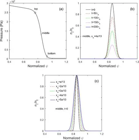
Figure 1.(a) Locations of x0 at the equilibrium pressure profile when SMBI is deposited at the top, middle and bottom of the pedestal.
Here,we first estimate the Coulomb collision frequencyνiiamong the thermal ions satisfying the Boltzmann distribution.We letνeibe the Coulomb collision frequency between the electrons and thermal ions in the plasma satisfying the Boltzmann distribution,then[32].In tokamak edge plasma, the typical Lundquist numberwhereνeiis about 105s−1[14].Therefore,νiiis about 103s−1.Next, we estimate the Coulomb collision frequencyν′′iiamong the cold ions satisfying the Boltzmann distribution.It can be seen from equation (2-5) thatThe speed of the thermal ionsViis about 105m s−1,and the speed of the cold ions seeded by SMBI is about 103m s−1.So we get
The cold ions and thermal ions obviously have not fully collided with each other.So the calculation ofν′iineeds to know the velocity distributions of the cold ions and thermal ions,respectively,and do a complex integral operation.In this work, we do not do direct calculation, but estimateν′iiin a more feasible way.According to equation (2-5), we assume the order of νii′is between the orders ofνiiandνi′i′,andνii′is proportional to ni′.That is to say, the order ofνii′is 103−108s−1,andνii′=kii′ni′,where kii′is a constant.According to the orders ofνii′and ni′,the order of kii′is 10−15−10−10m3s−1.Due to limited computing resources,and in order to see the impact of SMBI on an ELM in 100-200 Alfvén time τA(about 10−7s),the value ofνii′is set to about 105s−1,which changes with ni′.Correspondingly,kii′=10−13m3s−1,which is a fixed value.
In experiment, the cold ion density has fluctuating distributions in the poloidal and toroidal directions.In order to make the model more practical, we make an approximation that the density of cold ions is uniform in the poloidal and toroidal directions,but is set to change with time and satisfy a spatial distribution in the radial direction [28].
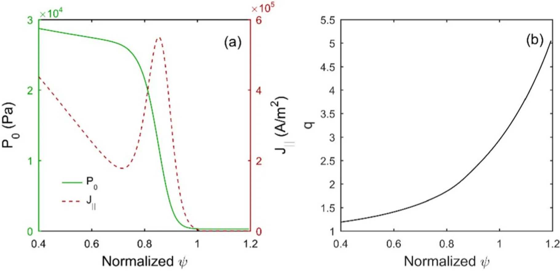
Figure 2.Radial equilibrium profiles of (a) pressure P0, parallel current density ‖J and (b) safety factor q.

wherenfis the amplitude of the cold ion density andtis the duration of the simulations.Fromt=0 tot=200τA, the amplitude of cold ion density decreases from the maximumnfto 0.xgis the grid number in thexdirection (i.e.the radial direction),x0is used to determine the central radial location of the distribution andxwis used to determine the width of the distribution.The distribution of′niis used to represent the distribution of SMBI deposited at the pedestal.Its distribution in the radial direction is shown in figure 1.
2.2.BOUT++ three-field equations with the impact of SMBI
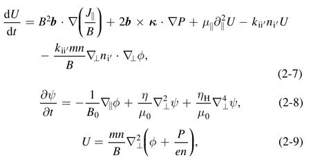
From equations (2-4) and (A5) in the appendix, we get three collision terms because of the impact of SMBI, which areWe call them momentum collision term,gradient collision term and energy collision term, respectively.The three-field equations [14]with these terms are,

The equilibrium used in the simulations is the cbm18_dens8 shifted circular equilibrium [33], which is unstable to P-B modes.The profiles of its pressure, parallel current density and safety factor are shown in figure 2.Its major radiusR0is3.4 m,minor radiusais1.2 m,toroidal field on axisB0is2 T,edge safety factorqais3.03,normalized betaβNis 1.51 and normalized pedestal widthis0.049.
The radial simulation range isis the normalizedψ.The inner radial boundary conditions are =U0,andThe outer radial boundary conditions areandφ= 0.In the simulations, a field-aligned (flux) coordinate system is used [34], whose coordinatesx,yandzare the radial-like,poloidal-like and toroidal-like coordinates.The simulation domain is periodic inyandz.The resolutions inxandyare 516 and 64, respectively.For efficiency, in the linear simulations,of the torus is simulated (nis the toroidal mode number),and the resolution inzis 16.In the nonlinear simulations,of the torus is simulated, and the resolution inzis 64.In a linear simulation fornmode, the given initial perturbation is a perturbation with only thenharmonic.In the nonlinear simulations,the given initial perturbation is a perturbation with only theharmonic.
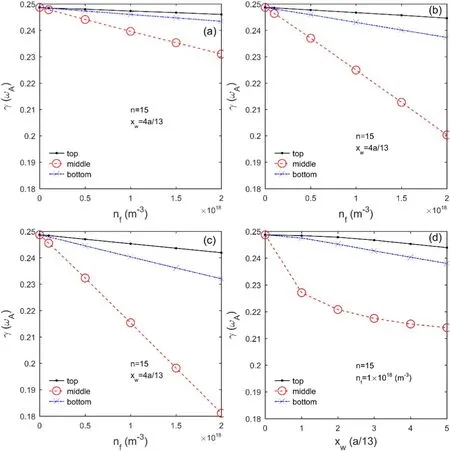
Figure 3.(a)Growth rates of the P-B modes with only the momentum collision term when nf is different.(b)Growth rates of the P-B modes with only the energy collision term when nf is different.(c) Growth rates of the P-B modes with both the momentum and energy collision terms when nf is different.(d) Growth rates of the P-B modes with both the momentum and energy collision terms when xw is different.
3.Results and discussion
3.1.Linear simulations
The equations with and without the collision terms are used to simulate ELMs.In order to simulate P-B modes, we setn=15.When there is no collision term, the growth rateγis 0.2487ωA,whereωA=VA/R0is the Alfvén frequency andVAis the Alfvén velocity.When there is only the gradient collision term, the growth rate does not change.When there is the momentum collision term or the energy collision term,the growth rate decreases.In the simulations,nfis set to 1 × 10¹⁷m−3,5 × 10¹⁷m−3,1 × 10¹⁸m−3,1.5 × 1018m−3and 2 × 10¹⁸m−3,xwis set toa/13, 2a/13, 3a/13, 4a/13 and /a5 13, andx0is set to locate at the top, middle and bottom of the pedestal.The growth rates are shown in figure 3, which have been normalized to an Alfvén frequencyωA.
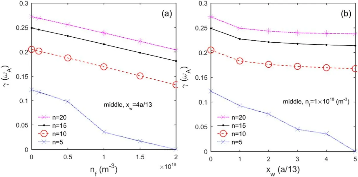
Figure 4.With both the momentum and energy collision terms, (a) growth rates of n=5, n=10, n=15 and n=20 modes when nf is different, (b) growth rates of n=5, n=10, n=15 and n=20 modes when xw is different.
As can be seen from figure 3, the momentum collision term or the energy collision term reduces the growth rate of P-B modes, and between them the energy collision term plays a leading role.The reduction amplitude of the growth rate is increased when the amplitude or width of SMBI is increased, and when SMBI is deposited at the top, bottom and middle of the pedestal,the reduction amplitude increases successively.
By contrast,when SMBI is deposited at the middle of the pedestal with both the momentum and energy collision terms,the effects of the amplitude and width of SMBI on the growth rate of =n5, =n10 and =n20 modes are also simulated.These modes are also considered to be P-B modes [14].In figure 4(a), the width of SMBI is fixed at /a4 13, and the effect of different amplitudes is investigated.In figure 4(b),the amplitude of SMBI is fixed at 1 × 10¹⁸m−3,and the effect of different widths is investigated.When the amplitude of SMBI reaches 2 × 10¹⁸m−3or the width of SMBI reaches 5a/13,then=5 mode hardly grows,and we simply think its growth rate is 0 without calculation.From figure 4,we know that the effects of SMBI on the P-B modes around n=5-20 are similar to =n15 mode.
From the linear simulation results, we conclude that increasing the amplitude or width of SMBI is helpful to suppress ELMs, and when SMBI is deposited at the top,bottom and middle of the pedestal, the impact of SMBI on P-B modes increases successively.These results are similar to that of Huang et al [27, 28].
3.2.Nonlinear simulations
In order to investigate the impact of SMBI on the ELM size,ELMs are simulated nonlinearly.The size of an ELM is defined as [11] the ratio of the energy loss (ΔWped) to the pedestal stored energy (Wped),

whereRinandRoutare the radial positions of the internal simulation boundary and the maximum pressure gradient,respectively.According to the results of linear simulations,both the momentum term and energy collision term are added to the equations used for nonlinear simulations, but the gradient collision term is neglected.
First,the impacts of the amplitude and deposited location of SMBI on the ELM size are simulated.The amplitudenfis set to 5 × 10¹⁷m−3,1 × 10¹⁸m−3,1.5 × 1018m−3and 2 × 10¹⁸m−3.The widthxwis set to 4a/13.The locationx0is set to locate at the top, middle and bottom of the pedestal.The corresponding ELM sizes are shown in figure 5.It can be seen that the SMBI reduces the ELM size.The largernfis,the smaller the ELM size is.When SMBI is deposited at the bottom, top and middle of the pedestal with the same amplitude and width, the ELM size decreases successively.
Comparing the result when SMBI is deposited at the pedestal top with the result when it is deposited at the bottom,there is a conflict between the linear and nonlinear simulations.The ELM size is smaller when SMBI is deposited at the pedestal top, but the corresponding P-B mode is more unstable.This conflict comes from the calculation of the energy lossΔWpedfor the ELM size in equation (3-1).Because of the location ofRout,〈P〉zincludes more pressure introduced from SMBI when SMBI is deposited at the pedestal top,which reduces the size ofΔWped.So the ELM size is smaller when SMBI is deposited at the pedestal top, even though the corresponding P-B mode is more unstable.
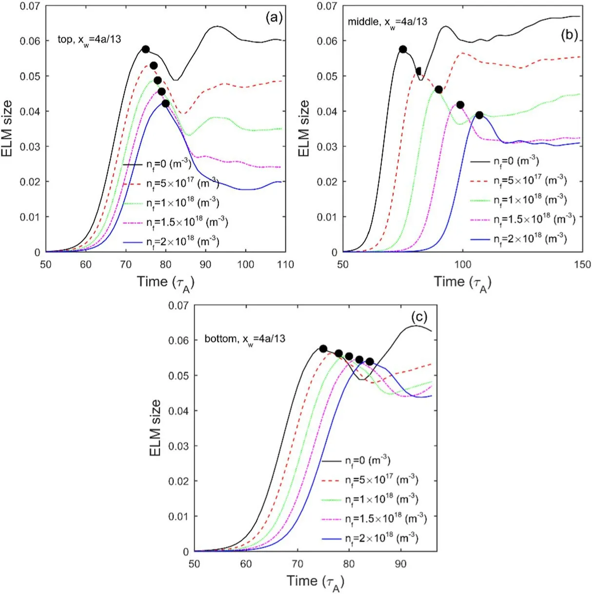
Figure 5.With different n f ,the evolution of ELM sizes when SMBI is deposited at the top (a), middle (b) and bottom (c) of the pedestal.
In figure 5, the time of a black dot corresponds to the time when filamentary structures of the ELM erupt [33].The pressure profiles averaged over (equilibrium) flux surfaces att=0 and at the times indicated by the black dots are shown in figure 6.The vertical axis is the total pressure (the sum of equilibrium pressure and toroidal average value of perturbation pressure) normalized by magnetic pressure.The black curve is the pressure profile at the beginning of the simulationt=0, which is the equilibrium pressure profile.The other curves represent the collapsed profiles at different times indicated by the black dots.Compared with the equilibrium pressure, due to the eruption of ELM, the inner part of the pressure profiles falls while the outer part of the pressure profiles rises.The only different parameter of (a), (b) and (c)in figure 6 is the deposited location of SMBI.Compared with the pressure profile of no SMBInf=0,when SMBI is deposited at the pedestal top,the reduction of the inner part of the pressure profiles is less,so that SMBI reduces the inward collapse amplitude of the pressure profiles.When SMBI is deposited at the pedestal bottom,the increase of the outer part of the pressure profiles is less, so that SMBI reduces the outward collapse amplitude of the pressure profiles.When SMBI is deposited at the pedestal middle, it reduces the collapse amplitude on both sides.The largernfis, the bigger the effect is.
In figure 7,pressure perturbations at the times indicated by the black dots in figure 5 are shown, which are considered to be the filamentary structures of the ELMs.They are shown within the view of normalized poloidal flux(x-axis) and toroidal angle (y-axis) at the outer mid-plane.The data in each slice are normalized to its absolute maximum.(b), (c) and (d) in figure 7 show the filamentary structures when SMBI is deposited at different locations with an amplitude of 2 × 10¹⁸m−3and a width of 4a/13.Compared with the result without SMBI in figure 7(a), the SMBI reduces the radial extent of the filamentary structures,and the effects are different when it is deposited at different locations.When SMBI is deposited at the pedestal top, it reduces the inner extent of the filamentary structures.When SMBI is deposited at the pedestal bottom, it reduces the outer extent of the filamentary structures.When SMBI is deposited at the pedestal middle, it reduces both the inner and outer extents.
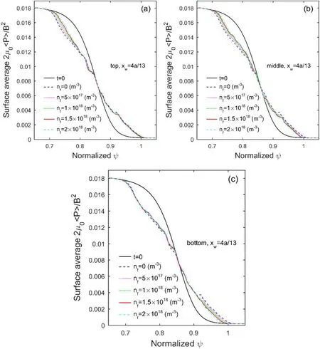
Figure 6.Surface-averaged pressure profiles when SMBI is deposited at the top (a), middle (b) and bottom (c) of the pedestal.
From figures 6 and 7, we conclude that when SMBI is deposited at the pedestal top, it reduces the inward collapse amplitude of the pressure profiles, which can improve the confinement efficiency during ELMs.When SMBI is deposited at the pedestal bottom, it reduces the outer extent of the filamentary structures, which can slow down the erosion of PFCs caused by ELMs.When SMBI is deposited at the middle of the pedestal,it has the above two effects at the same time.Therefore,to slow down the erosion of PFCs caused by ELMs,shallow deposition of SMBI such as at the middle and bottom of the pedestal is better.This can meet the needs of ELM mitigation.This conclusion is similar to that of Rhee et al [26].
Finally, the impact of SMBI width on the ELM size is simulated.The amplitudenfis set to 1 × 10¹⁸m−3,the widthxwis set to /a2 13, /a3 13, /a4 13 and /a5 13,and the locationx0is set to locate at the top, middle and bottom of the pedestal.The corresponding ELM sizes are shown in figure 8.It can be seen that the SMBI reduces the ELM size.The largerxwis, the smaller the ELM size is.So when the width of SMBI is increased, its impact on the ELM size is increased.
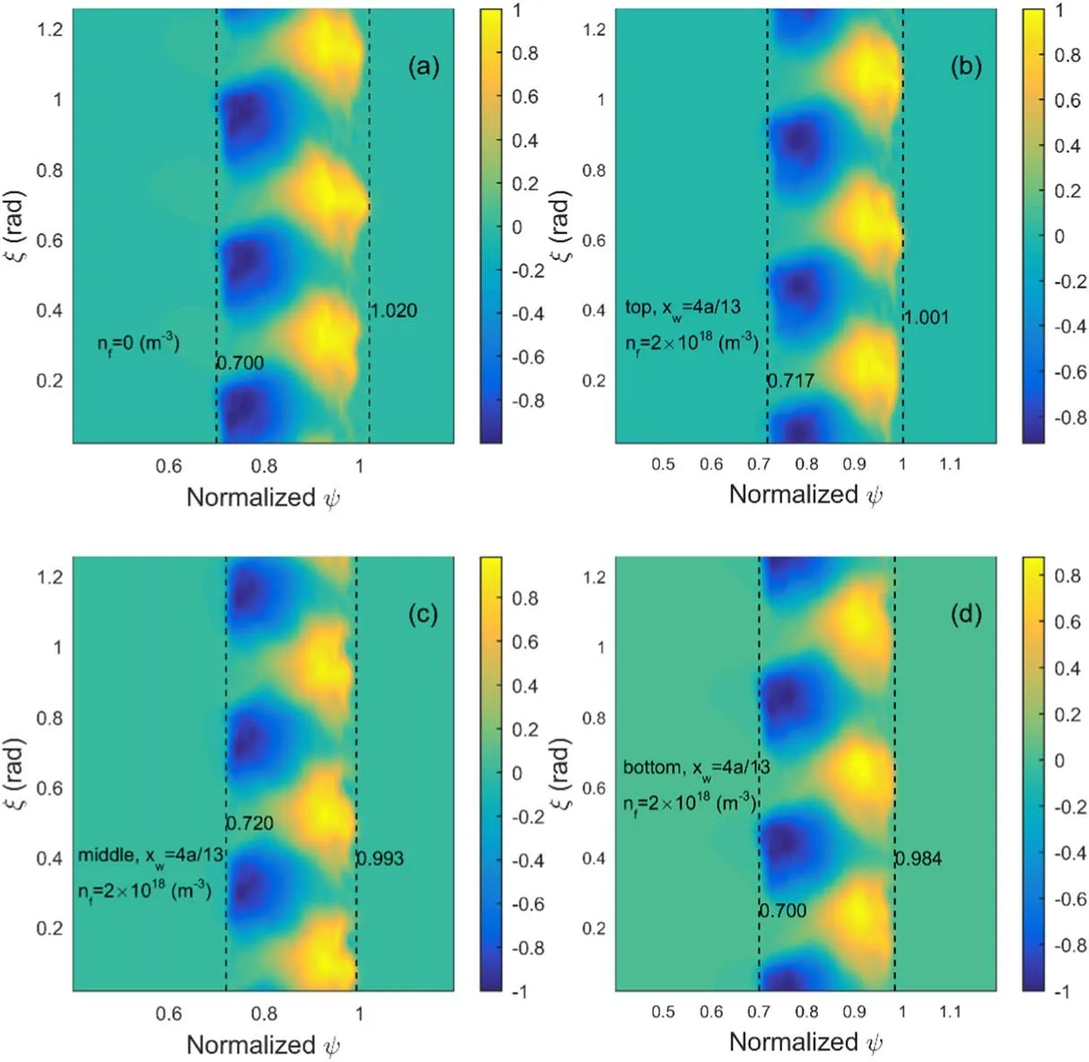
Figure 7.Pressure perturbations in the frame of normalized poloidal flux and toroidal angle when there is no SMBI(a), and when SMBI is deposited at the top (b), middle (c) and bottom (d) of the pedestal.
4.Summary
In this work,collision terms representing the impact of SMBI are added to the three-field equations in the BOUT++ code.The impact of SMBI on ELMs is investigated by linear and nonlinear simulations.The simulation results are analyzed and compared with others to find an optimal SMBI scenario.Linear simulation results show that the momentum collision term or the energy collision term reduces the growth rate of P-B modes, and between them the energy collision term plays a leading role.The reduction amplitude of the growth rate is increased when the amplitude or width of SMBI is increased, and when SMBI is deposited at the top,bottom and middle of the pedestal, the reduction amplitude increases successively.Thus, increasing the amplitude or width of SMBI is helpful to suppress ELMs,and when SMBI is deposited at the top,bottom and middle of the pedestal,the impact of SMBI on P-B modes increases successively.
Nonlinear simulation results show that SMBI reduces the ELM size, and the reduction amplitude of the ELM size is increased when the amplitude or width of SMBI is increased.Moreover, when SMBI is deposited at the bottom, top and middle of the pedestal with the same amplitude and width,the reduction amplitude increases successively.Surface-averaged pressure profiles and filamentary structures are analyzed when the ELMs erupt.When SMBI is deposited at the top or middle of the pedestal, it reduces the inward collapse amplitude of the pressure profiles.This can improve the confinement efficiency during ELMs.When SMBI is deposited at the middle or bottom of the pedestal, it reduces the outer extent of the filamentary structures, which can slow down the erosion of PFCs caused by ELMs.Through the above results, we think that shallow deposition of SMBI such as at the middle and bottom of the pedestal with sufficient amplitude and width can meet the needs of ELM mitigation.
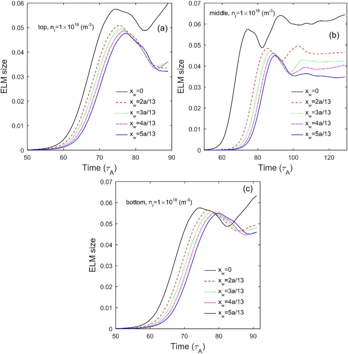
Figure 8.With different x w ,the evolution of ELM sizes when SMBI is deposited at the top (a), middle (b) and bottom (c) of the pedestal.
Acknowledgments
The authors wish to thank X Q Xu and B D Dudson for their contributions to the BOUT++framework and R D Hazeltine for his contribution to plasma theory.This work was supported by the National Key R&D Program of China (Grant Nos.2018YFE0303102 and 2017YFE0301100).This work was also partially supported by National Natural Science Foundation of China (Grant No.11675217) and the Youth Innovation Promotion Association of Chinese Academy of Sciences (Grant No.2017479).
Appendix.Deducing the momentum equation into a vorticity equation
LettingF= −∇P+J×Bin equation (2-1), we get,

If the left side of equation (A1) is denoted byfii′,the shear-Alfvén law is obtained [31]:

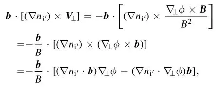
The first term on the left side of equation (A2) is,

It is equivalent to,


In the direction perpendicular to the magnetic field, only the contribution ofE×Bdrift is included in the velocity[31].That is to say,so that


ORCID iDs
Yuanzhen WANG (王元震) https://orcid.org/0000-0001-5943-301X
 Plasma Science and Technology2020年12期
- Plasma Science and Technology的其它文章
- The structure of an electronegative magnetized plasma sheath with non-extensive electron distribution
- The effect of forced oscillations on the kinetics of wave drift in an inhomogeneous plasma
- Effect of background fluctuation on velocity diagnostics by Mach probe
- Mitigation of blackout problem for reentry vehicle in traveling magnetic field with induced current
- New method for rekindling the explosive waves in Maxwellian space plasmas
- Molecular dynamics simulations of the interaction between OH radicals in plasma with poly-β-1-6-N-acetylglucosamine
