Research on oil film characteristics of piston pairin swash plate axial piston pump①
Wang Xiaojing (王晓晶)②, Sun Yuwei, Shen Zhiqi
(School of Mechanical and Power Engineering, Harbin University of Science and Technology, Harbin 150080, P.R.China)
Abstract
Key words: axial piston pump, piston pair, oil film characteristics, model pump, numerical analysis
0 Introduction
The axial piston pump is widely used in the field of aviation and other fluid transmission with compact structure and high power density[1]. The piston pair is one of the main friction pair of piston pump. Because the friction pair works at high speed and heavy load state for a long time and the lubrication condition is quite complex, the friction pair becomes an important factor affecting the performance, reliability and life of the piston pump[2-4]. The oil film clearance and the fluid in the piston chamber of axial piston pump which was analyzed based on three-dimensional Navier-Stokes equation, was focused on the static lubrication characteristic of friction pair, and the established model did not correlate the mechanical property of the friction pair with the fluid property[5]. Ref.[6] analyzed the friction and lubrication characteristic of the axial piston pump at low speed by using the oil lubricated friction and lubricating property rule. Ref.[7] found that the friction loss between piston pair and slipper pair was the main power loss source of axial piston pump and analyzed the influence of the friction interface with different surface morphology on reducing friction performance of piston pair by theoretical and experimental tests. Ref.[8] built a 3D simulation model of 35 MPa high-pressure axial piston pump distribution pair. The slip grid technology and dynamic grid technology were used to perform computational fluid dynamics (CFD) numerical simulation on the secondary flow field of the piston pump distribution, which visualized pressure field, velocity field, and temperature field of the secondary oil film for flow distribution. Tang et al.[9,10]used the finite difference method and the finite element method to analyze the variation of oil film thickness in different piston cavities, and demonstrated that thermal deformation and elastic deformation affected the heat of the shoe. However, the above two simulation analyses are limited to theory, and there is no experiment as an argument. Ref.[11] studied the theory of passive oil film lubrication based on the lubrication characteristic of non-metallic materials. It was analyzed that the theory of non-metallic slipper and passive oil film lubrication could be applied to many kinds of piston pump.
In this work, the characteristics of the piston oil film are simulated and tested under the change of spindle speed and load pressure. Taking A10VSO series piston pump as an example, the model of the piston pump system is simulated by AMEsim. The piston pump spindle speed are 1 500 r/min, 1 200 r/min, 900 r/min, 600 r/min respectively, and the load pressure are 18 MPa, 12 MPa, 6 MPa. According to Reynolds equation and the finite volume discretization method, the thickness distribution of the cylinder is obtained. The oil film thickness experiments under the corresponding working parameters are designed with the single piston of model pump. During the experiment, the oil film thickness with 18 MPa is sampled, which is closer to the actual working environment. The simulation model is verified by the experiment, which plays a guiding role in the piston pair research.
1 Piston cavity pressure solution
In order to obtain the piston cavity pressure, the hydraulic and dynamic models of A10VSO skew axial piston pump are simulated by AMEsim, and the spindle speed is set to 1 500 r/min, load pressure 18 MPa and inclined angle 18 °[9,12-14]. The whole model of axial piston pump is shown in Fig.1, and the liquid pressure curve of the piston is shown in Fig.2. The liquid pressure at the bottom of the piston is the fluctuating periodic force, and the change period is the rotation period of cylinder body.
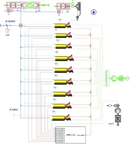
Fig.1 Axial piston pump model
2 Lubrication model and numerical solution of piston pair oil film
2.1 Analysis on piston posture in cylinder hole
The resultant force causes the piston to tilt in the cylinder hole, and the piston axis is not superposed with the cylinder bore axis. The position relationship is shown in Fig.3. The value {e1,e2,e3,e4} of the axial eccentricity vector was developed by Wieczorek and Ivantysynova and accurately defined the local film thicknesshat each point in the fluid domain[15], wheree1ande2represent the axial and radial offsets of the end of the plunger respectively,e3ande4represent the axial and radial offsets of the front of the plunger respectively.
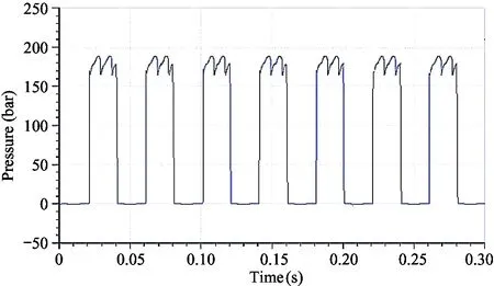
Fig.2 Piston hydraulic pressure curve
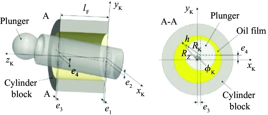
Fig.3 Schematic diagram of piston tilt state
The coordinate of the eccentric piston axis relative to the rectangular coordinate system is determined as follows.
(1)
After the coordinate of the slanted piston shaft is clearly defined, the oil film thickness of the secondary piston can be obtained by solving the following equation.
h(z,φk)=

-Rk+Δh
(2)
where,φk=18 ° is the piston pole angle,Rz=33.5 mm is the cylinder radius,Rk=8.5 mm is the piston radius, Δhindicates the extrusion effect of the micro motion on the oil film thickness.
Assuming that the clearance is smaller than the piston radius, the lubricant curvature is neglected. The rectangular coordinate system is introduced, and the oil film thickness of piston pair is expressed as Eq.(3) in the Cartesian coordinate system.
(3)
2.2 Reynolds equation
The Navier-Stokes equation of Newton fluid representation is
(4)
where, ▽ is the gradient, ▽• is the dispersion,ρis the oil density,Vis the volume,μis the oil viscosity,Pis the pressure.
Referring to Cartesian coordinate system, the lubrication interface is defined in the plane so thatzis the direction of the film thickness, as shown in Fig.4.
According to the establishment of lubrication theory hypothesis, Navier-Stokes equation is greatly reduced to the following formula.[16-18]
▽P=▽•(μ▽V)
(5)
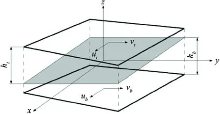
Fig.4 Fluid film geometry, the gray plane being z=0
The Descartes component is generated as follows.
(6)
The expression of the fluid velocity obtained through Eq.(6) in the permissible thickness of oil film is shown as
(7)
Considering the inclination of the upper and lower surfaces,htandhbare the distance (with symbols) from the bottom and the top surface to the reference planez=0 and the actual film thickness (h=ht-hb).
The Reynolds equation is derived from integrating the expression of the fluid velocity in the incompressible continuity equation into the thickness direction of the fluid film. The final result of the integration ignores the stretching condition, which can be expressed as

=0
(8)

(9)


(10)
The boundary condition is very critical to solve the Reynolds equation. So here we choose the Reynolds boundary condition. If the pressure and the first derivative of the pressure are zero, it can ensure flow continuity without negative pressure. The boundary conditions are as follows:


Periodic boundary conditions:
(11)

The pressure distribution of the piston is calculated by the boundary condition of the oil film.
In order to establish an integral expression equivalent to the initial value of the Reynolds equation, Weiczorek and Ivantysynowa proposed a method of computing interstitial fluid membranes through computer technology. The interstitial fluid between the piston and the cylinder was simulated by the model tool CASPAR. The design parameters were inputted into the simulation program and the motion equations of the corresponding components were solved by iterative method. The range of fluid film was divided into a computational grid. Element method and element volume method were used to calculate the interstitial fluid film. The combination realized the iterative coupling between micro motion.
The solution of oil film thickness field can be described as follows. To solve the Reynolds equation, the oil film between piston block and cylinder block are divided into many grids. Using the pressure value on each node to form the difference quotient, the derivative of the Reynolds equation is substituted. The equations are transformed into algebraic equations, and the algebraic equations represent the relation between the unknown quantity of each unit and the unknown quantity of the surrounding units. Then, the pressure value of the whole field is obtained by solving the equations according to the iterative method.
Take the operating conditions as follows:Plunger cavity pressure is 18 MPa, motor speed is 1 500 r/min, piston radius is 8.5 mm, average clearance between plunger and cylinder bore is 10 μm, swash plate angle is 18 °, radius of distribution circle is 33.5 mm, oil dynamic viscosity is 39.1 Pa ·s. The oil film thickness distribution can be calculated by these parameters.
3 Numerical analysis of piston pair oil film thickness
3.1 Effect of pressure load
Based on AMEsim, the plunger pump model can be simulated. The angle speed of the pump is set to 1 500 r/min, and the load pressure is set to 18 MPa. The piston pair simulation also requires the input of the piston chamber pressure, as shown in Fig.2. The cylinder rotates around 0-360 °. Similar cylindrical piston pair oil film is deployed in Cartesian coordinate system demonstrated by Eq.(3). When the cylinder in the oil discharge area rotates with the main shaft to 30 °, the cylinder rotates through the triangular groove of the valve plate, the oil outlet of the valve plate communicates with the piston chamber, and the oil film begins to be compressed under the action of the pressure load. When the cylinder rotates with the spindle to 210 °, the piston located in the bore of the cylinder is now located in the suction area, and the external force applied to the piston is reduced. The results of the numerical solution of oil film thickness field in 0-180 ° oil exhausting area are shown in Fig.5.
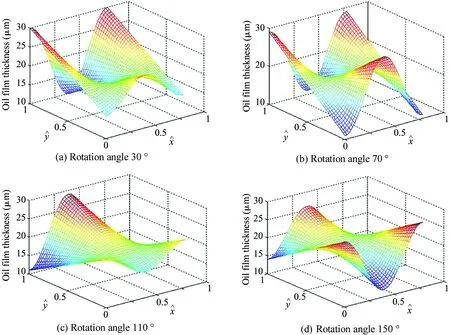
Fig.5 Oil film thickness in oil drainage area
The change law of oil film thickness fluctuation range, the average oil film thickness and the rotation angle of cylinder body is shown in Table 1. Promptly the maximum average thickness of the oil film in the oil discharge area is 24 μm when the rotation angle of cylinder body is different.
The numerical solution of the thickness field of the piston pair oil film in 180-360 ° oil absorption area is described in Fig.6. The average oil film thickness of piston pair at 4 different angles in the oil absorption region is 20-21 μm, and the average oil film thickness is basically stable.
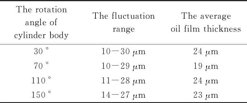
Table 1 Comparison of oil film thickness in oil drainage area
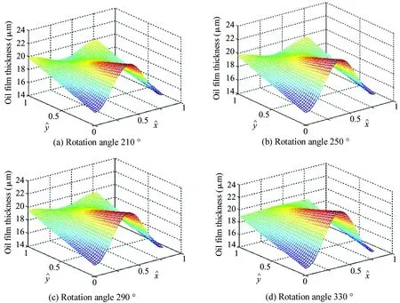
Fig.6 Oil film thickness in oil absorption area
According to the simulation, the oil film thickness of the oil-absorbing zone is basically stable when the spindle speed is 1 500 r/min and the load pressure is 18 MPa, owing to the fact that when the piston is in the low pressure zone, the oil pressure in the piston cavity is the fuel tank pressure.
3.2 Effect of rotation speed
The influence of the load pressure on the dynamic lubrication performance of piston pair is mainly manifested in the high pressure area, while the oil film thickness in the low pressure area remains basically unchanged, which is mainly due to the oil pressure in the piston chamber when the piston is in the low pressure area. The following focuses on the situation of the oil film lubrication of piston pair in the high pressure zone. The change trend of the oil film thickness of piston pair under different parameters of cylinder body rotating to 70 ° is studied when the piston is located in the oil drainage area. The speed is set to 600 r/min, 900 r/min, 1 200 r/min and 1 500 r/min and the pressure is set to 6 MPa, 12 MPa and 18 MPa accordingly. The oil film thickness distribution of piston pair is shown in Fig.7 under different pressures when the piston speed is 1 500 r/min. As can be seen from Table 2, the maximum average thickness of oil film is 24 μm under different load pressures.

Table 2 Comparison of oil film thickness with speed 1 500 r/min
The distribution of the oil film thickness field of piston pair is shown in Fig.8 under different pressures when the spindle speed is 1 200 r/min. It can be seen from Table 3 that promptly the maximum average thickness of the oil film is 35 μm when the load pressure is different.

Fig.7 Oil film thickness of piston pair with speed 1 500 r / min

Fig.8 Oil film thickness of piston pair with speed 1 200 r/min

Table 3 Comparison of oil film thickness with speed 1 200 r/min
The distribution of the oil film thickness field of piston pair is shown in Fig.9 under different pressures when the spindle speed is 900 r/min. It can be seen from Table 4 that the maximum average thickness of the oil film is 33 μm when the load pressure is different.

Fig.9 Oil film thickness of piston pair with speed 900 r/min

Table 4 Comparison of oil film thickness with speed 900 r/min
The distribution of the oil film thickness field of the piston pair is shown in Fig.10 under different pressures when the spindle speed is 600 r/min. It can be seen from Table 5 that promptly the maximum average thickness of the oil film is 34 μm when the load pressure is different.
The analyses of the oil film thickness of piston pair with different spindle speeds from Fig.7 to Fig.10 show that the oil film thickness of the piston is increasingly fluctuant with the speed decreasing. That is, with the higher speed, it is more conducive to produce the stable oil film.

Fig.10 Oil film thickness of piston pair with speed 600 r/min

Table 5 Comparison of oil film thickness with speed 600 r/min
4 Experiments
In order to verify the change law of oil film thickness of piston pair, the model pump was used in the experiment.[19-22]The experiment platform for the oil film of the axial piston pump is shown in Fig.11.
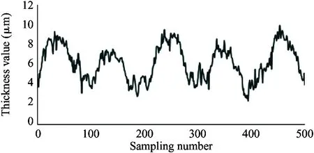
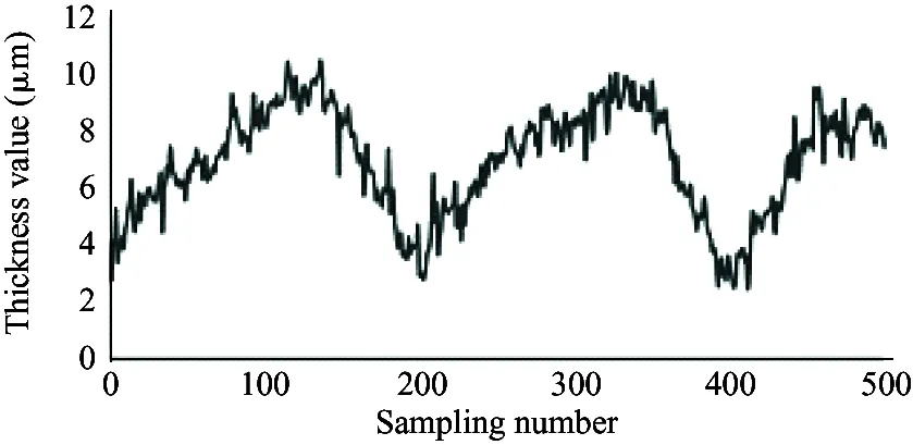
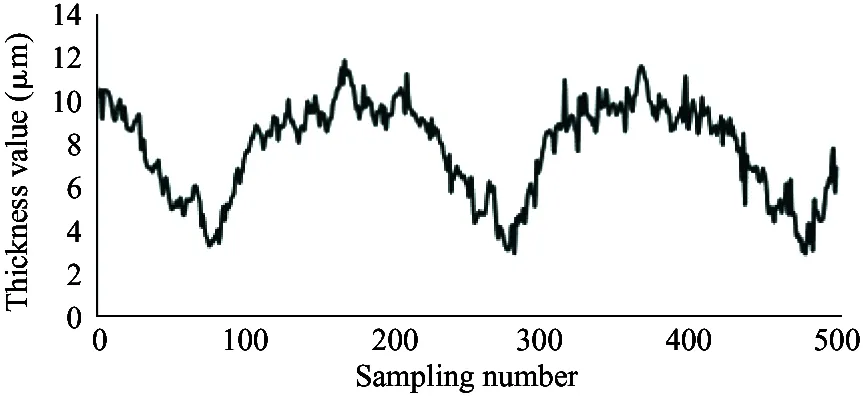
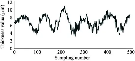
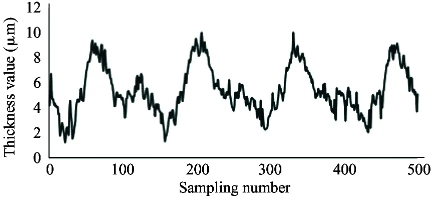
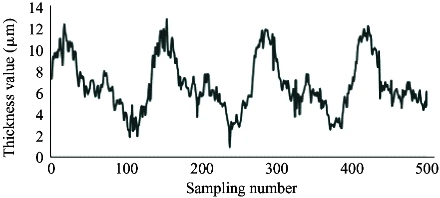
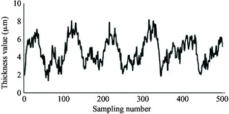
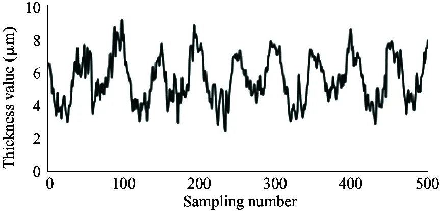
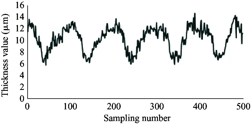
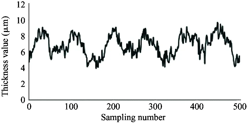
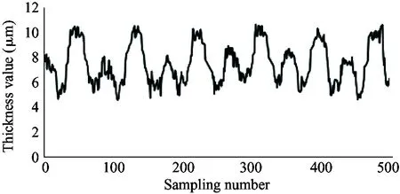
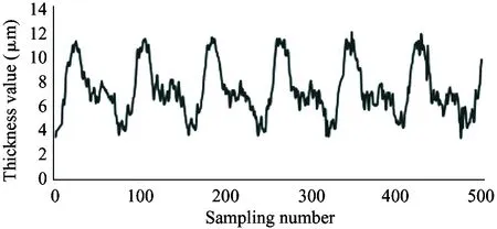
It is required that the selected sensor does not suffer the effect of contaminants and lubricating oil, and also the sensor itself needs to bear high temperature (200 ℃). Therefore, the electric eddy current displacement sensor made by German micro-epsilon Company is chosen. The pressure is up to 70 MPa and the probe diameter is only 2.5 mm. The sensor is placed on the surface of the plunger sleeve and the distance from the sensor to the plunger head is equal to the distance from the sensor to the plunger end. In order to compare the simulation results with the experiment results, the experiment used 4 different speeds (600 r/min, 900 r/min, 1 200 r/min and 1 500 r/min) and the output pressure is 6 MPa, 12 MPa and 18 MPa. Data results are obtained by 5 sensors installed to measure the oil film thickness, as shown in Fig.12.
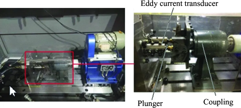
Fig.11 Oil film test bench for piston pair
As shown in the experiment data in Fig.12, the oil film thickness varies periodically. The oil film thickness varies significantly in high pressure, and the thickness fluctuation is small in low pressure. The oil film thickness varies greatly in low speed, and the thickness fluctuation is small in high speed. The minimum oil film thickness increases with the speed increasing.
Because the experiment and simulation were established under the same influence factors, by comparing the results of simulation with that of the experiment, it can be illustrated that the variation of the oil film thickness is related to the spindle speed and load pressure. At the same time, the higher the load pressure, the greater the change of oil film thickness. When the load pressure is fixed, the larger the spindle speed, the smaller the change of oil film thickness. It also shows that the thickness of oil film changes periodically. The simulation results are consistent with the results of oil film thickness change, and the feasibility of the simulation model is proved. However, due to the leakage in the actual distribution side, it is reasonable to find that the actual oil film thickness is smaller than the simulation result by observing the simulation graph and experimental curve. Considering the model pump feasibility, the motor drives the rotation of the swash plate, which is different from the model set by the simulation model that the motor drives the spindle, so the experiment value and the simulation value of the oil film thickness is different. In this paper, the influence of spindle speed and load pressure on the film thickness of the cylinder is explained, which presents the design direction of piston pump in the future.
4 Conclusion
The fluid pressure of piston cavity was calculated by AMEsim simulation. The piston differential equation was used to describe the oil film thickness of piston pair in Cartesian coordinate system, and the oil film thickness model of piston pair was established. The simulation results show that the piston oil film thickness fluctuates in a certain range when the piston is subject to a large oscillating load in high pressure. When the piston in the cylinder block is located in the suction area during the period from 180 ° to 360 °, the force applied to the piston is reduced. Due to the low power load, the pressure field is relatively moderate, and the oil film thickness is basically unchanged. The results show that the oil film thickness is more and more fluctuant with the speed decreasing. The higher the speed is, the more stable the oil film is. The experiment model pump was designed, and the oil film thickness was measured. The simulation results of the oil film thickness of piston pair are verified by experiments. It is proved that the simulation model of piston pump established in this paper has important guiding significance for the design of axial piston pump.
(a) 600 r/min, 6 MPa
(b) 600 r/min, 12 MPa
(c) 600 r/min, 18 MPa
(d) 900 r/min, 6 MPa
(e) 900 r/min, 12 MPa
(f) 900 r/min, 18 MPa
(g) 1 200 r/min, 6 MPa
(h) 1 200 r/min, 12 MPa
(i) 1 200 r/min, 18 MPa
(j) 1 500 r/min, 6 MPa
(k) 1 500 r/min, 12 MPa
(l) 1 500 r/min, 18 MPa
 High Technology Letters2020年3期
- High Technology Letters的其它文章
- Image texture smoothing method by a novel L0-norm optimization model①
- Health status assessment of axial piston pump under variable speed①
- Comparison of availability and reliability among differentcombined-GNSS/RNSS precise point positioning①
- Design of a DSLM-based cerebral palsy action rehabilitation training system①
- Mobility matrix of a weakly coupled parallel multi-DIM isolator based on axial force solution①
- Detecting and adaptive responding mechanism for mobile WSN①
