High-precision and wide-range real-time neutron flux monitor system through multipoint linear calibration
Ren-Jie Zhu· Xiang Zhou· Zi-Hao Liu· Wen-Di Wang ·Xiao-Li Mou · Teng-Fei Fang · Qing-Li Ma · Xiu-Feng Xu · Guo-Liang Yuan ·Li Zhao · Ling-Feng Wei · Ze-Jie Yin
Abstract The neutron flux monitor (NFM) system is an important diagnostic subsystem introduced by large nuclear fusion devices such as international thermonuclear experimental reactor (ITER), Japan torus-60, tokamak fusion test reactor,and HL-2A.Neutron fluxes can provide real-time parameters for nuclear fusion, including neutron source intensity and fusion power. Corresponding to different nuclear reaction periods, neutron fluxes span over seven decades, thereby requiring electronic devices to operate in counting and Campbelling modes simultaneously. Therefore, it is crucial to design a real-time NFM system to encompass such a wide dynamic range. In this study, a high-precision NFM system with a wide measurement range of neutron flux is implemented using realtime multipoint linear calibration. It can automatically switch between counting and Campbelling modes with variations in the neutron flux. We established a testing platform to verify the feasibility of the NFM system,which can output the simulated neutron signal using an arbitrary waveform generator. Meanwhile, the accurate calibration interval of the Campbelling mode is defined well.Based on the above-mentioned design, the system satisfies the requirements, offering a dynamic range of 108 cps, temporal resolution of 1 ms,and maximal relative error of 4%measured at the signal-to-noise ratio of 15.8 dB. Additionally, the NFM system is verified in a field experiment involving HL-2A, and the measured neutron flux is consistent with the results.
Keywords Multipoint linear calibration · Real time ·Simulated neutron signal · Neutron flux monitoring ·ITER · HL-2A
1 Introduction
ITER is a core experimental platform constructed to investigate the controlled nuclear fusion reaction and provide guidance for the optimized design and operation of fusion power plants [1]. To comprehensively monitor the entire nuclear fusion reaction process,it is vital to develop reliable diagnostic systems to collect all the necessary plasma parameters to protect the machine,improve plasma performance, and promote physics studies [2–7]. Among them, the NFM system is one of the major diagnostic systems used for measuring the total neutron flux, and it has been used since the initial design phase of the ITER[8–10].Neutron flux measurement is performed to evaluate neutron emissivity and is central for understanding the behavior of nuclear fusion reactions [11]. Generally, the NFM system comprises two parts, i.e., fission chamber detectors and an electronic processing module [12].Because many gamma signals are generated during the reaction, it is important to select fission chamber detectors with a high neutron gamma (n/γ) suppression ratio.Meanwhile,the traditional NFM system is based on analog circuits with simple discrimination algorithms [13, 14].Consequently,complex offline analysis must be performed to ensure the accuracy of neutron multiplicity counting,and the raw data used to require a considerable amount of storage space [15–17]. Meanwhile, the neutron flux of the ITER exhibits a wide range from 1014to approximately 1021n/s [18], rendering it difficult to satisfy such a wide requirement range only through the single counting or Campbelling mode in electronics.
In this study, we designed a high-precision and widerange real-time NFM system through multipoint linear calibration.The digital pulse shape discrimination(DPSD)module, which is based on a high-speed analog-to-digital converter (ADC) and field-programmable gate array(FPGA), can be applied to organic scintillators and liquid scintillation detectors in counting mode.Owing to the highdegree integration of digital circuits, we can easily implement real-time discriminating algorithms. To encompass the wide dynamic range of neutron fluxes,the counting and Campbelling modes (known as ‘‘fluctuation mode’’ or‘‘mean square voltage mode’’) were integrated into the system.Real-time multipoint linear calibration can be used to solve the crossover between counting and Campbelling modes, and improve the accuracy of neutron fluxes in the Campbelling mode. Using multipoint linear calibration in the overlapping interval of the Campbelling and counting modes, we can obtain the exact conversion coefficients between the Campbelling value and the real neutron flux.Subsequently, the measurement dynamic range of the neutron flux can be extended to 108counts per second(cps). Compared with the DSP unit prototype of Toshiba[19],the NFM system has a faster time response of 0.2 ms and a temporal resolution of 1 ms. In particular, the simulated neutron signal processed by an arbitrary waveform generator,which is consistent with the characteristics of the output waveform of the fission chamber detector, was performed to measure the accuracy of the system. Using simulated neutron signals overcomes the shortage of actual neutron sources.Furthermore,the simulated neutron signal has universal applicability;hence, it can be used widely in the evaluation of neutron flux measurement systems.Based on the design above, the noise margin of the system was obtained,and the relative error of the neutron counting rate did not exceed 4% because the accurate calibration intervals of the Campbelling mode were analyzed well. The measured counting rate was much higher than the 10%accuracy required for the neutron flux measurement [20].
2 Design principles of NFM system
The NFM system primarily comprises four modules,i.e., fission chambers (FCs), charge sensitive preamplifiers(PAs), main electronics (MA), and monitoring software of the upper computer.The overall block diagram is shown in Fig. 1, where PXI represents peripheral component interconnection extensions for instrumentation.
2.1 Fission chamber
The fission chamber is a gas counter containing235U[12, 21–23] mainly composed of fissile material coating and a gas ionization chamber.When the neutron enters the ionization chamber, a nuclear reaction occurs with fissile material UO2on the cathode, and hundreds of MeV of energy is released. Subsequently, the generated fission fragments further react with the gas when passing through the ionization chamber. Finally, the generated ions are collected by the electric fields of the positive and negative electrodes to form a charge pulse signal. Correspondingly,the energy released by the neutron is orders of magnitude larger than the γ-ray and hard X-ray;therefore,pulse shape discrimination is unnecessary for235U FCs. In field experiments involving the HL-2A Tokamak device, the amplitudes of the gamma and noise were approximately tens of millivolts, but the amplitudes of the neutron pulse signal exceeded 200 mV. Therefore, we set approximate discrimination threshold, and only signals with pulse amplitude greater than the threshold were recognized as neutron pulses.

Fig. 1 (Color online) Overall block diagram of NFM system
2.2 Preamplifier design
The charge signal output from the fission chamber is extremely weak and disappears easily owing to the highoutput impedance. Meanwhile, some electromagnetic interference and noise effects were inevitable in the experimental environment. The pulse signal cannot be distinguished from the noise if the long-line transmission(150 m from FC to MA) is performed directly. Therefore,the charge pulse signal output from the fission chamber must be amplified and processed with a signal conditioning circuit to improve the anti-interference ability.
The charge-sensitive preamplifier is mainly composed of four-stage amplifiers (see Fig. 2). The negative pulse output from the FC is first input to the first stage (A1) for integral amplification, which involves a charge-sensitive amplifier with high input impedance. Subsequently, the signal passes through the second and third stages (A2and A3, respectively) of the high-gain amplifier. Finally, the signal passes through the fourth stage (A4) of the lowoutput impedance inverted amplifier and then outputs a positive pulse. Considering that the range of input signals for the MA should not exceed 5 V, the amplitude of a single neutron pulse should be limited to less than 300 mV after being processed by the preamplifiers.

Fig. 2 (Color online) a Structure of charge-sensitive preamplifier;b main structure of MA
2.3 High-speed MA design
In recent years,with the increase in ADC sampling rate,DPSD technology has piqued significant research interest owing to its flexible processing and strong scalability for digital signals. In this study, we designed MA capable of extracting valuable information from analog signals. The ADC sampling rate was as high as 250 million samples per second with a 12-bit width.The designed MA is crucial for processing the digital signal of the entire system and controlling the operation of each module. The system can support three boards to collect data in parallel and then upload the data to the host computer through the PXI bus interface. The overall design diagram is shown in Fig. 2,where ACC represents alternating current coupling, PGA represents programmable-gain amplifier, and DCI represents digital Campbelling integrator.
An FPGA was adopted to calculate the Campbelling integral value of the sampling data from the ADC,and the calculation was based on the Campbelling theorem [24].The output voltage of the detector can be described based on the current impact Qδ(t),where Q is the strength of the current impact, i.e., the amount of charge carried. Considering that the detector is a linear time-invariant system that can be depicted by an impulse response function h(t),the impulse in the interval from τ to τ + dτ will contribute to the output voltage at time t. Here, λ represents the average counting rates of the impulse signal,and the events of nuclear radiation induced by the detector obey the principle of Poisson distribution over time; therefore, the average counting rate is λdτ for the interval from τ to τ + dτ. The average contribution of the output voltage at time t is as follows:

where u(t) is the unit step function. The root-mean-square deviation of the output voltage at time t is attributed entirely to the randomness of the number of pulses n.According to the Poisson mean square distribution equation, the root-mean-square deviation can be obtained, as follows:

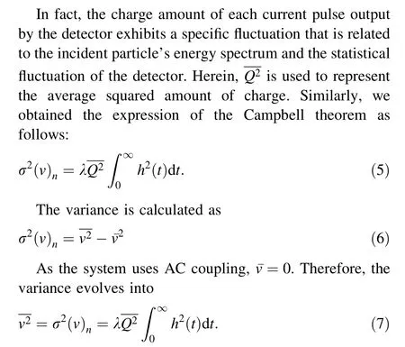
Considering the high-speed parallel operation ability of the FPGA,we integrated the main algorithms to the FPGA to process the signal in real time. The output signal of the preamplifier was transmitted to the analog signal processing module of the MA for conditioning. This module is mainly used for (1) AC coupling, which can remove the DC signal (required by Campbell’s theorem); (2) gain controlling, which enables the signal to reach the ADC sampling requirement via FPGA control; and (3) translating the single-ended signal into a differential signal,which enables the ADC to perform sampling.Next,the signal was input to the ADC digital sampling module of the MA;hence,the analog signal was converted into a digital signal(250 M). Finally, the digital signal was processed by the FPGA module of the MA, which exhibits high-speed computing capabilities owing to the parallel computing afforded by the FPGA. Limited by the uploading speed of the PXI bus,we ultimately focused on only the neutron flux for the experimental results. Therefore, the raw data sampled by the ADC was first processed using the FPGA;subsequently, the as-obtained result of counting rate and Campbelling value without calibrating was uploaded to the host PC through the PXI bus.This module is crucial for(1)performing n/γ discrimination according to the pulse amplitude, pulse width, and other parameters; (2) calculating counting values and the integral values of Campbelling;(3)controlling the operation of the system;and(4)packaging the calculation result of the FPGA and uploading them to the PXI bus.
2.4 Software design
The data processed by the FPGA can only be stored in RAM resources; hence, the contents will disappear once the power is turned off.Therefore,it is necessary to upload the calculated data to the host computer through the PXI bus.Subsequently, we calibrated the Campbelling value in real time based on the multipoint linear strategy. The overall design of the host computer software is shown in Fig. 3.
When the neutron flux was in the overlapping range of 104to 105cps [25, 27], the counting and Campbelling values were both accurate. Furthermore, the rising process of the neutron flux must be sufficiently wide to contain the calibration interval in the actual fusion reaction such that the Campbelling values can be calibrated using the data of the overlapping region. Subsequently, the correlation between the actual neutron flux and the Campbelling values can be obtained.Finally,the actual neutron flux can be calculated directly from the calibration result.
As shown in Fig. 3, the data uploaded by the FPGA is mainly the counting and Campbelling values per time interval.The calibration module continuously monitors the counting values uploaded from the FPGA. To reduce the error caused by the calibration, the accurate calibration intervals of Campbelling and counting were divided equally into 10 subintervals.Only a set of data containing a counting value and a Campbelling value for each subinterval was selected for calibration in the same experiment.The 10 as-obtained sets of data were linearly fitted via the least-squares method to obtain values of linear correlation coefficients, intercepts, and slopes. Generally, there exists only one rising edge containing calibration interval in the same experiment. Therefore, calibration was usually performed only once in each discharge experiment; subsequently,the neutron flux was obtained using the calibration coefficients and Campbell values.
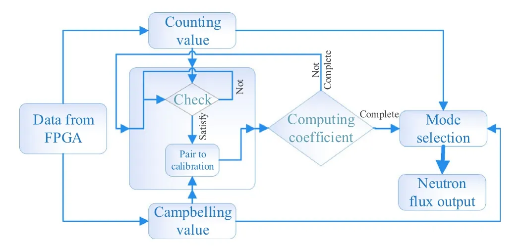
Fig. 3 Flowchart of multipoint linear calibration algorithm
3 Simulated signals of neutron pulse
Owing to the harsh conditions of using the neutron source and the complex operating environment, it was challenging to directly obtain the actual neutron signal pulses that represent the actual neutron flux of fusion reaction in the laboratory. Therefore, we developed a system for simulating the output signal of the fission chamber.First, the data for simulating a neutron signal was generated using MATLAB; subsequently, a waveform was output using an arbitrary waveform generator (Keysight 81160A).
3.1 Principle
The single neutron signal of the fission chamber satisfies formula (8),

where Q is the amount of charge released from the fission chamber[28](set to Q = 0.5 pC),R is the equivalent input resistance of the preamplifier (set to R = 5 kΩ), τ is the electronic collection time of a fission reaction in the fission chamber (set to τ = 400 ns), w = 1/RC, and C = 200 pF.The resulting single pulse neutron waveform was similar to the waveform shown in Fig. 5. Meanwhile, the waveform of simulated single neutron pulse is based on the measured single neutron pulse on HL-2A(Fig. 8),and the waveforms of the two agreed well with each other.
The statistical characteristics of the fission chamber’s output signal satisfy the following: (1) In the nuclear physics experiment, the number of particles recorded by the detector within a certain period of time is completely independent. Therefore, the number of particles recorded by the detector in a certain period of time can be regarded as a Bernoulli experiment. When the probability of event A is sufficiently small (p ≪1) and the number of experiments n is large and np tends to a finite value λ, then the binomial distribution is approximately a Poisson distribution. (2) The amplitudes of the fission chamber pulses are proportional to the energy absorbed by the incident particles, and random fluctuations exist in the absorbed energy,which can be represented by the Gaussian distribution in a general simulation. The standard deviation of the distribution σ = R × A/2.33, where R represents the detector’s intrinsic energy resolution, and A represents the average value of the pulse amplitude.(3)Owing to the interference of environmental factors such as detectors and electronic devices,noise simulated by the Gaussian distribution noise will be introduced during the measurement of the neutron signal. (4) The PA is treated as a linear time-invariant system that satisfies the principle of superposition. The superposition of neutron waveforms was processed by superimposing the amplitudes linearly.
According to the principles above,the simulation of the neutron pulse waveform is formed by the superposition of three parts, i.e., a single neutron pulse waveform whose amplitude satisfies the Gaussian distribution, a Poisson distribution sequence, and a noise signal satisfying a random distribution (Fig. 4).
3.2 Results
Based on the method above, the simulated neutron signals with neutron fluxes ranging from 105to 108cps can be obtained (Fig. 5). In MATLAB, we designed a graphical user interface that can adjust the parameters to simulate the waveforms for all neutron flux ranges.
4 Results and discussion
Under laboratory conditions, it is difficult to obtain the neutron source that satisfies the counting rate requirement for the acquisition system. Hence, we simulated neutron signals to verify the feasibility of the NFM system in advance.Simulated waveforms with counting rates of 103–108cps were generated using an arbitrary waveform generator (Keysight 81160A) and then input to the MA for neutron flux measurement. We obtained the relative error by comparing the measured and theoretical results.
4.1 Union test using simulated signals
Based on the characteristics of the neutron pulse,a pulse waveform with counting rates of 103to 108cps was generated using a Keysight 81160A arbitrary waveform generator.The width of a single neutron pulse was from 200 to 400 ns, the pulse amplitude A satisfied the Gaussian distribution A ~N(μ,σ2),where(μ = 250 mV, σ = 10 mV),and the Gaussian white noise Vpp= 150 mV (99.7%). Thecounting and Campbelling values were uploaded to the PC and compared with the theoretical values. The obtained relative error is shown in Fig. 6.As shown in Fig. 6,when the counting rate of the neutron was less than 4.04 × 10⁵cps, the relative error of the counting mode was less than 2.23%. When the counting rate of the neutron was greater than 2.2 × 10⁴cps,the relative error of Campbelling mode was less than 3.14%. Correspondingly, the relative error was independent of the width of the single neutron signal.In particular, the relative error with the neutron counting rate from 2 × 10⁴to 4 × 10⁵cps was less than 2.28% in the Campbelling mode and 2.23% in the counting mode;therefore, this overlapping interval was regarded as the calibration interval for the Campbelling mode in the following experiments, and the counting rate of 4 × 10⁵cps was set as the switching point for the counting and Campbelling modes. Furthermore, the simulation verified that the relative error of the NFM system was less than 4%,indicating that the NFM system significantly improved the accuracy of the neutron flux measurement.
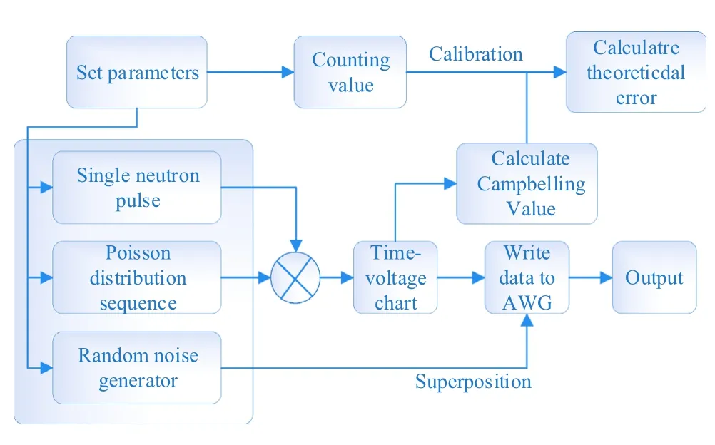
Fig. 4 Algorithm of simulated neutron signal generation

Fig. 5 Simulated neutron signals with neutron fluxes from 105 to 108 cps
4.2 Experimental results on HL-2A
A field experiment was performed on this system using the HL-2A Tokamak device of the Southwest Institute of Physics, where high-purity235U fission chambers were used. The plateau length was from 300 to 800 V, slope of the plateau was ≤0.9%, sensitivity was 1 ± 0.15 cps/nυ,and insulation resistance was 2 × 10⁹Ω [29]. The completed system is shown in Fig. 7, including the HL-2A Tokamak device and the NFM system. In addition, a hardware trigger module was introduced to the system to compare with other measurement results of HL-2A; this trigger module can respond to the trigger signal of HL-2A and then can trigger the board of the MA to begin operation through the PXI bus (clock zero).
When operating in the counting mode, the noise threshold must be set appropriately to remove the effects of noise and γ rays. First, a graph with a neutron pulse was captured in the oscilloscope mode (another function of the system), as shown in Fig. 8; the noise amplitude of the system was ± 50 mV. To improve the system accuracy,we set the noise threshold above 50 mV to remove the effect of noise on the counting rate of the neutron. Furthermore, the rising time of the single neutron pulse was approximately 80 ns, the pulse width was approximately 300 ns, and the amplitude was approximately 300 mV,indicating a typical neutron pulse signal.
In shot 31,231,the MA measured the number of neutron pulse signals output from the fission chamber; the specific results are shown in Fig. 8. The counting rate of the neutron pulse signals measured by this system increased from(502 ms,0 cps)to(511 ms,40,000 cps)and then stabilized for approximately 489 ms before finally decreasing from(1000 ms, 50,000 cps) to (1037 ms, 0 cps). In general, the curve of the counting rate of the neutron pulse signals shows the same trend as that of the power of the neutral beam injection (PNBI). In detail, the PNBI began increasing at 499.14 ms and then reduced to 0.57 kW at 1003.41 ms. The duration of the neutron pulse signals measured by the NFM system was approximately 535 ms,in accordance with the duration of neutral beam injection(NBI) for 504.27 ms as the neutrons were only generated during NBI. Furthermore, the measured duration of the neutron pulse signals was longer owing to the relaxation time of the nuclear reaction.However,the neutron flux was insufficient to reach the switching point of the Campbelling and counting modes. Based on the experimental results above, we confirmed that the system is reliable and applicable for measuring neutron fluxes.
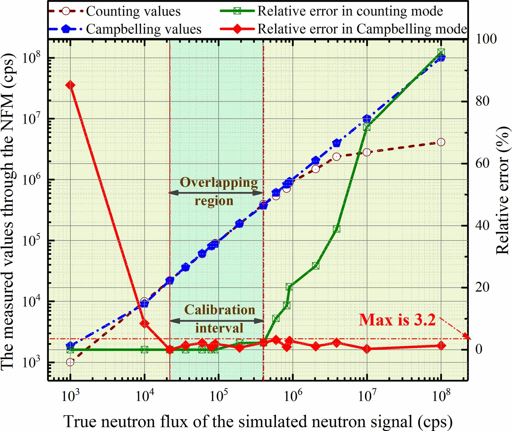
Fig. 6 (Color online) Measured neutron flux and relative error of counting and Campbelling modes

Fig. 7 (Color online) Construction of NFM system on HL-2A
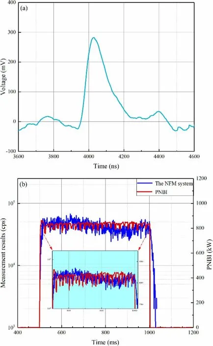
Fig. 8 (Color online) a Single neutron pulse waveform, b measurement of counts of neutron pulses and PNBI on HL-2A
5 Conclusion
In this study, we designed a high-precision and widerange real-time NFM system and proposed a multipoint linear calibration algorithm. Both the counting and Campbelling modes were employed for the MA, and the measured dynamic range of the neutron flux was extended to 108cps with the maximal relative error of 4%. In addition, the characteristics of the neutron pulse signals were described, and neutron signals superimposed with noise were simulated. Using the simulated neutron signals solved the deficiency of the actual neutron source, and the simulation afforded universal applicability;hence,it can be used widely to detect neutron fluxes. Additionally, the NFM system was validated through a field experiment involving HL-2A, and the measured neutron flux was consistent with the results.
Despite the achievements above, the system requires further verifications based on field experiments involving the ITER.Furthermore,it is still challenging to resist noise and suppress interference under strong electromagnetic fields when the cable between the FC and PA is increased to 50 m long.
 Nuclear Science and Techniques2020年9期
- Nuclear Science and Techniques的其它文章
- Digitalization of inverting filter shaping circuit for nuclear pulse signals
- Development of a low-loss magnetic-coupling pickup for 166.6-MHz quarter-wave beta = 1 superconducting cavities
- Scheme for generating 1 nm X-ray beams carrying orbital angular momentum at the SXFEL
- Investigating the effect of entrance channel mass asymmetry on fusion reactions using the Skyrme energy density formalism
- Correction to: Theoretical prediction of radiation-enhanced diffusion behavior in nickel under self-ion irradiation
- Preparation of large-area isotopic magnesium targets for the 25Mg(p,γ)26Al experiment at JUNA
