
Volumetric Langmuir probe mapping of a transient pulsed plasma thruster plume
2020-09-14 01:13WilliamYeongLiangLING林永樑ShuaiLIU刘帅XiangyangLIU刘向阳ZhiwenWU武志文andNingfeiWANG王宁飞
Plasma Science and Technology 2020年9期
William Yeong Liang LING (林永樑),Shuai LIU (刘帅),Xiangyang LIU (刘向阳),Zhiwen WU (武志文) and Ningfei WANG (王宁飞)
School of Aerospace Engineering,Beijing Institute of Technology,Beijing 100081,People’s Republic of China
1 Authors to whom any correspondence should be addressed.
Abstract
Keywords:Langmuir probe,pulsed plasma thruster,micropropulsion,electron density,plasma expansion
1.Introduction
The miniaturization of technology has spurred the advent of smaller and smaller satellites in recent years.While traditional satellites such as communications satellites and the satellites in the Global Position System (GPS) can weigh several thousand kilograms,technological miniaturization has enabled the development of satellites weighing as little as 1 kg or less.The most well-known nano/microsatellite architecture is the CubeSat architecture,where 1 unit(1U)has dimensions of 10×10×10 cm3[1].Each unit typically weighs around 1 to 2 kg and multiple units can be combined to form larger architectures,e.g.2U,3U,6U,etc.
It has been estimated (SpaceWorks 2019 Nano/Microsatellite Market Forecast) that around 2000 to 2800 nano/microsatellites(1 to 50 kg)will be launched over the next five years [2].At present,most of these satellites are delivered with no propulsion systems.This severely restricts their ability to maneuver,perform orbital changes,or even to deorbit.One main limitation is that while it has been possible to miniaturize the electronic systems,it has been much more challenging to develop suitable efficient micropropulsion systems [3].Typical electric thrusters such as Hall thrusters and ion thrusters require at least 40 W of power,while CubeSats may be restricted to as little as several W of solar power.
One possible solution to this is the pulsed plasma thruster(PPT) [4-6].PPTs are a simple form of electric propulsion that have been studied for decades.They were also the first electric propulsion system to be operated in space [7].While Hall thrusters and ion thrusters have dominated in applications with higher electrical power availability (e.g.conventional satellites) [8],PPTs have the ability to be easily miniaturized to the low power levels of several W required by nano/microsatellites.One example is the Busek MPACS PPT,which operates at a power level of <10 W with a specific impulse of 827 s.The Busek BmP-220 is another micropropulsion system that can operate at 1.5 W with a specific impulse of 536 s.These very low power requirements make them ideally suitable for use as propulsion systems for nano/microsatellites.
While PPTs are very structurally simple,the simplicity belies the complex physics and plasma processes that take place during their operation [4-6].A typical PPT consists of electrodes (a cathode and anode),a main energy storage capacitor,propellant (typically polytetrafluoroethylene,aka.PTFE),and a spark plug to initiate the main discharge process.A side-view image of the light emission from a PPT is shown in figure 1,demonstrating the complex pattern of the plasma plume.

Figure 1.The PPT discharge (side view).The reference origin is located at the indicated point,i.e.the geometric center at the exit of the thruster.The plasma plume travels downstream in the positive x-direction.The cathode is located in the positive z-direction,while the anode is located in the negative z-direction.The y axis is perpendicular to the page.The spark plug can be seen above the cathode.The ablated surface of the propellant is to the left of the figure,while a Langmuir probe is located inside the plasma plume to the right.
The bulk of the energy is stored inside the main capacitor.The electrodes are separated by the propellant,which is insulating.The spark plug is usually a high-voltage spark gap discharge or a semiconductor spark plug.The energy stored in the spark plug circuit is negligible compared to that in the main capacitor.The initiation spark from the spark plug provides a conductive pathway for the main capacitor to discharge between the electrodes and across the propellant surface.A discharge arc then forms between the electrodes that ablates and ionizes the propellant to form a plasma.The plasma is then accelerated downstream by the Lorentz force caused by the self-induced magnetic field of the PPT.The entire discharge process typically lasts only several microseconds,resulting in an instantaneous power of the order of MW,far higher than the average power consumption level of the order of W.After the end of the pulse discharge,the main capacitor is then charged again in preparation for the next discharge.In this way the PPT operates in discrete pulses,each providing a very small impulse bit,enabling the delivery of very accurate thrust levels by controlling the number of pulses.The pulse frequency of a PPT is typically of the order of Hz.
All the physical processes in a PPT occur within a time scale of microseconds,making it extremely difficult to study.It was also seen in figure 1 that the plasma plume can take on complex patterns.To better understand the fundamental processes behind the operation of PPTs,there has been significant work done in probing the plasma physics of both the inter-electrode space and the plasma plume [6,9-15].Inside the inter-electrode space,where the plasma density is higher and the plasma itself is more active,collisions and interactions in the plasma result in the emission of light(such as that recorded in figure 1).This spectral emission can be used in spectroscopy to study the plasma parameters during the operation of a PPT[9].Alternatively,high-speed cameras can also be used to study the evolution of the plasma plume [9,13].
However,further downstream from the PPT,the light emitted from the plasma plume decreases significantly,making it difficult to use such methods.Furthermore,highspeed cameras and spectroscopy are limited to observations along the line-of-sight.For example,a high-speed camera capturing the side view of a PPT essentially captures a twodimensional (2D) spatially-integrated profile of the plasma.The three-dimensional (3D) behavior of the plasma is not known.On the other hand,if the camera is placed in front of a PPT,it will then capture all the light emitted,with no information regarding the depth of the data.Similarly,spectroscopy is limited to line-integrated data,meaning that the information recorded is integrated along the entire line-ofsight,giving us no depth information.
Alternatively,plasma probes such as Faraday cups and Langmuir probes can be used to probe specific locations in space to study the local plasma parameters [10,14,15].Langmuir probes are widely used in the study of plasmas as they conveniently enable measurements of the plasma parameters.Langmuir probes are especially useful as they can provide an estimate of the local electron density and electron temperature over time at a 0-dimensional (0D) point.
The simplest Langmuir probe is the single Langmuir probe,consisting of a single electrode that is biased with a voltage ramp relative to the ground.This voltage ramp gives us the current-voltage (I-V) characteristics of the Debye sheath around the probe,from which the parameters of the plasma flowing towards the probe can be determined.However,the ground of a PPT is inherently unstable due to the significant energy released during a discharge and the oscillating discharge current and voltage.To alleviate this,a double Langmuir probe can be used,where the first electrode is biased relative to a second floating electrode,rather than the ground.This way,there is no longer any reference to the object being studied,making it less susceptible to interference from the PPT discharge.On the other hand,an I-V curve is still required.For a transient plasma,such as that from a PPT,each discharge will only be able to provide data for one point on the I-V curve (as there is no time to sweep through the voltage range),necessitating many discharges in order to build up the I-V curve before the plasma parameters can be determined.
A further improvement on the double Langmuir probe is the triple Langmuir probe,where two electrodes are biased with a fixed voltage and a third electrode is floating within the plasma [16].This results in one electrode recording the electron current,while another records the ion saturation current.The triple Langmuir probe enables real-time probing of the plasma,meaning that each PPT discharge can then yield time-dependent data on the plasma parameters,avoiding the need to slowly build up an I-V curve as with the single and double Langmuir probes.This has significant advantages in the study of short-lived transient plasmas,such as the one that exists in the plume of a PPT.Understandably,the triple Langmuir probe has thus been used extensively in the study of PPTs [10,14,15].
The triple Langmuir probe is typically operated either at an arbitrary location in the plume of the thruster,or along set downstream distances to probe the change in the plasma plume as it expands into vacuum.However,as the probe essentially measures a 0D point in space,it can also be moved to different locations to effectively map out both the temporal and spatial behavior of the plasma plume.Experimentally,this can be simply achieved with a mobile probe that can be moved around inside the plasma plume.
In the past,data analysis and data visualization of the massive amount of temporal and spatial data would have been more challenging than at present.Most experiments were typically performed at set distances along the downstream axis from a thruster,giving us a 1D understanding of the plasma parameters with time.With improvements in computing technology,it has become relatively simple to process 0D Langmuir probe data in order to create either 2D or 3D spatial maps of the plasma parameters with time.This can enable the visualization and further understanding of the 3D spatial behavior of the plasma plume,something that is not possible using high-speed cameras or emission spectroscopy.In this work,we demonstrate how 2D and 3D maps of the plume of a PPT can be generated from Langmuir probe measurements,giving us further insight into the complex plasma patterns and behavior.
2.Langmuir probe theory
The theory behind the triple Langmuir probe has been described in detail in several past studies.The typical error levels associated with PPT measurements has also been investigated previously.A brief overview of the triple Langmuir probe and the relevant equations is discussed here,but more detailed information and discussion beyond the scope of the current work can also be found within the literature [14,15].
The triple Langmuir probe was first proposed several decades ago in 1964 by Chen and Sekiguchi [16].It was presented as a means to determine the instantaneous values of the electron density and temperature,while also enabling the direct display of these values during experiments.This has the significant advantage of simplifying the data processing procedures that are usually required with single and double Langmuir probes.This was particularly important due to the computer processing limitations of the past.
Beginning in the late 1990s and early 2000s,owing to the advantages that triple Langmuir probes exhibit in the study of transient plasmas,they were used to probe the electron density and temperature in the plume of a PPT [14,15,17].As mentioned previously,triple Langmuir probes do not require a voltage sweep,making them ideally suited for PPTs with their microsecond-level pulse duration.

Figure 2.A schematic of a triple Langmuir probe.Electrode 2 is floating in the plasma,while a voltage of Vd3 is applied between electrodes 1 and 2.The voltage difference between electrodes 1 and 2(Vd2(t))and the current I3(t)is collected to enable the evaluation of the electron density ne(t) and the electron temperature Te(t).
A schematic of a typical triple Langmuir probe and its three electrodes is shown in figure 2.
The electron temperature can be estimated by solving the implicit equation,which assumes the thin-sheath currentcollection model:

whereχdn=χn-χ1=(e∣Vn-Vp∣-e∣V1-Vp∣)/(kTe)are the non-dimensional potentials at electrodes n=1,2,and 3 measured with respect to the plasma potentialV.pHere,e is the elementary electron charge,k is Boltzmann’s constant,and Teis the electron temperature.From this,the electron density (ne) can then be calculated using:
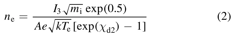
where I3is the time-dependent current recorded from the probe between electrodes 1 and 3,miis the average ion mass,A is the probe collection area,and the other variables are as previously defined.The Debye length (λd) can be calculated using

whereε0is the permittivity of free space,and all other variables are as previously defined.
For a PPT,the Debye length is of the order of μm,which is much smaller than the dimensions of the probes usually used(typical diameters are of the order of 0.1 to 1 mm).These initial estimates can also be improved using other ion currentcollection models other than the thin-sheath current-collection model[15].Note that with the triple Langmuir probe,it is also not necessary to directly determine the plasma potential Vpin equation (1).With the electrode potentials being measured respective to the plasma potential,the plasma potential terms will subsequently cancel out in the definition of the nondimensional potential.

Figure 3.PPT discharge voltage.The reference time t=0 is the beginning of the main discharge.At this point,a significant drop in voltage occurs as energy is discharged across the electrodes.
In this paper,to simplify the calculations,the thin-sheath model is implicitly assumed.Nevertheless,as the Debye length for the PPT is much smaller than the probe dimensions,we have found that for a PPT,the results from the thin-sheath model are close to those of the improved models,but require less iteration in the calculation process.For our experimental conditions,the uncertainties discussed in the literature[14,15]are greater than the difference in the calculation results from the model used.This is also in accordance with previous works where the thin-sheath assumption is used when the electrode radii are greater than 100 times the Debye length.As mentioned earlier,detailed discussion of these uncertainties and errors can be found in the literature and is beyond the scope of this work,which instead focuses on the data visualization of the results.
However,as it has been rarely addressed,we will note here that in equation (2),in order to calculate the electron density,a value for the ion mass miis required.For the PPT here,this is implicitly assumed to be the average ion mass of the propellant C2F4(discussed further in the next section).It is also possible to estimate a correction factor to account for the presence of multiple ion species (the value is close to unity for C2F4) [18].However,should more complex propellants [19]such as non-volatile liquids [20,21]or electric solid propellants [22,23]be used,or should the ionization ratio of the propellant components vary significantly from equilibrium,it will be important to examine this variable carefully.The implicit assumption of this ion mass is also the reason that we will refer to the values here as the estimated plasma parameters.Nevertheless,it does not change the results regarding the distribution and general behavior of the plasma.The Langmuir probe can thus be considered to be a semi-quantitative method for studying the transient plasma of a PPT.Potential future improvements will be discussed in later sections of this paper.
3.Experimental methods
The experiments were performed in a vacuum chamber with a diameter of 1 m and a length of 1.2 m.The chamber is equipped with rotary pumps and turbopumps that bring it to a base pressure of the order of 10−3Pa before experiments were performed.The experimental PPT had parallel electrodes with a length of 20 mm and an electrode separation of 25 mm.The capacitance of the main capacitor was 10 μF with a maximum voltage of 2 kV,giving a maximum discharge energy level of 20 J.However,most of the experiments here were performed at a voltage of 1 kV and a corresponding discharge energy level of 5 J.This is because at closer probe distances to the PPT,the probe had a tendency to be overloaded at higher discharge energy levels.Nevertheless,the entire process outlined here can be repeated with higher energy levels,providing that the nearest probe distance studied does not overload the probe.
The triple Langmuir probe used in the experiments had electrode diameters of 0.3 mm.The exposed length of the electrodes was 10 mm and the electrode material was tungsten.The electrodes were housed inside a cylindrical ceramic structure (serving as the probe body) that is resistant to plasma exposure.The probe was shielded from electromagnetic interference by covering the external surface of the probe using copper foil.The electrical ground of the probe was separated from the electrical ground of the PPT to avoid interference from the fluctuating ground produced by the PPT.
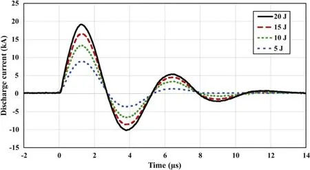
Figure 4.PPT discharge current.The reference time t=0 is the beginning of the main discharge.At this point,there is an increase in the discharge current to the kA level as plasma is generated between the electrodes.The subsequent oscillations correspond to restrikes that generate secondary plasma pulses.

Figure 5.Maximum electron density versus downstream distance for a PPT discharge energy of 5 J.This data is taken along the centerline of the PPT,i.e.(y,z)=(0,0).
The applied bias voltage must be high enough to enact conditions of electron and ion saturation currents from the electrodes,but also does not have to be excessively high.This can be determined by measuring data from a position of interest using several different bias voltages,and selecting an appropriate voltage that enacts these conditions for the duration of the discharge (i.e.the current should not invert during the discharge).In addition,when considering that many positions (including downstream positions) have to be measured for volumetric data,an appropriate bias voltage should enact these conditions for all points for the duration of the discharge,meaning that we now have to consider the spatial variation in addition to the temporal variation.We tested bias voltages of 30 to 70 V for our experimental conditions,and a bias voltage of 40 V was found to be appropriate.
To clean the probe surfaces,the electrodes of the probe were connected to a high-voltage power supply and a cleaning electrode.This process has also previously been demonstrated in the literature [14,15].When cleaning,the pressure in the vacuum chamber is raised to the order of 0.1 Pa.A bias voltage of 1 kV is introduced between the cleaning electrode and the probe,resulting in the formation of a glow discharge.This cleaning process was performed to remove surface deposits from extensive exposure to the plasma.
The probe was located on a three-axis translation stand that enabled the probe to be moved to specific areas of interest in the plasma plume.The origin (0,0,0) was defined to be located at the PPT exit,and was the point between the electrodes in the center of the PPT (see figure 1).For the experiments here,the downstream range probed was x=4 to 9 cm from the PPT exit,y=−2 to 2 cm left/right of the PPT(perpendicular to the line connecting the two electrodes),and z=−4 to 4 cm up/down (parallel to the line connecting the two electrodes).The step size for all axes was 1 cm,and the spatial resolution limit will be discussed later in the paper.
For data collection,the discharge voltage of the PPT was recorded using a Tektronix THDP0100 high-voltage differential probe and the discharge current was recorded using a PEM CWT MiniHF 150R Rogowski coil.These served to provide a reference point for time t=0,which was defined to be the point at which the main discharge began(a drop in the discharge voltage from the charging voltage and a rise in the discharge current from zero).Here,Vd2was measured from the triple Langmuir probe using a second Tektronix THDP0100 probe operating in a lower voltage mode,and I3was measured using a Tektronix TCP0030A current probe.The data was simultaneously recorded on a Tektronix MDO3024 oscilloscope for each PPT discharge.Several discharges were recorded for each point in space to ensure the consistency and reliability of the data.Data processing and visualization was performed using MATLAB.In this paper,we will focus primarily on the electron density results,but similar processes can be used for the electron temperature.

Figure 6.Electron density as a function of downstream distance from the PPT exit.For conciseness,only distances of x=4,6,and 8 cm are shown.These curves correspond to the centerline of the PPT,i.e.(y,z)=(0,0).The reference time t=0 is the beginning of the main discharge.Here,t=0 to 1 μs is omitted for conciseness,and a short time delay can be seen before the arrival of the first plasma pulse is recorded,which increases with the distance from the exit.
4.Results and discussion
Figures 3 and 4 show typical discharge voltage and current curves,respectively,for the experimental PPT at several different discharge energy levels.As can be expected,the discharge current increases with increasing discharge energy.This will in turn result in a change in the plasma parameters of the plasma plume.Each PPT discharge was extremely repeatable,which is a fundamental requirement for data collation.
The maximum electron density recorded using the triple Langmuir probe is shown in figure 5 as a function of the downstream distance (x).The maximum electron density can clearly be seen to decrease with downstream distance from the PPT exit as a result of the expansion of the plasma into vacuum.The electron temperature along the centerline was in the range of 10 eV for our experiments.These values are similar to those previously measured in the plume of a PPT[14,15,17].
In figure 6,we can see the electron density over time as a function of the downstream distance from the PPT exit.For each individual curve,we can observe that the electron density rises rapidly (corresponding to the primary peak of the discharge current)before falling.In the process,several peaks are visible.These can be attributed to the discharge current reversals seen in figure 4,which produce secondary plasma pulses in what are known as ‘restrikes’ [9].These restrikes further stress the main capacitor as they result in additional charge/discharge cycles,but can be minimized in the optimization stage of PPT design[6,24].We can also see that as we go further downstream,the electron density decreases due to the expansion of the plasma into vacuum.
Another interesting phenomenon that can be observed is the presence of plasma pairs,with one peak being much larger than the other.At x=4 cm,four peaks are clearly visible,forming two pairs.From comparison with the half-wavelength of the PPT’s discharge current,each pair is likely to be associated with the plasma pulses produced by a half-wavelength current pulse,i.e.the large pulse is associated with the positive half-wavelength current pulse while the smaller pulse is associated with the negative counterpart,with both forming a pair over one wavelength of the current discharge (with half-wavelengths of ∼2.5 μs).At closer distances (4 cm in figure 6),we are able to clearly observe a pulse associated with both the positive and negative half-wavelength current pulses.At further distances (8 cm in figure 6),only a single pulse is clearly distinguishable where there were previously two.The smaller pulse appears to have diffused,with the leading edge of the smaller pulse melding into the trailing edge of the larger pulse.Similarly,the trailing edge of the smaller pulse melds into the leading edge of the following pulse.Where a total of four peaks were clearly visible at 4 cm over the entire discharge time,only two are readily distinguishable at 8 cm.This phenomenon is similar to that mentioned in the literature,where fast-moving plasma was detected along with slow-moving plasma in the plume of a PPT [25].We postulate that depending on the plasma expansion behavior of a given PPT,further downstream measurements may potentially be measuring the merged plasma pairs,i.e.only the large remaining peaks seen at 8 cm in figure 6.In such cases,velocity measurements further away from the exit would thus give us the mean velocity of the combined pair.In addition to the previously identified behavior of the leading edge of the plasma plume [10],this demonstrates the extremely complex nature of plasma plume expansion from a PPT.In the future,this phenomenon can be studied in further detail using either simultaneous downstream measurements from the same plasma pulse,or a quadruple Langmuir probe [14].

Figure 7.Electron density versus time along the central x-z slice where y=0.The unit for the electron density is m−3.The minimum scale is 1×10¹⁸ m−3,and the maximum scale is 2.5×10²⁰ m−3.The reference time t=0 is the beginning of the main discharge.Each x-z slice at every time step consists of measurements from 54 positions (6×9).
The Langmuir probe results in figures 5 and 6 are typical of those recorded from a PPT,i.e.measurements are usually performed along the centerline(the x-axis in this case,with y and z=0) at various distances from the thruster’s exit.Each curve in figure 6 is the time-dependent 0D data of the local plasma parameters,and multiple downstream points give us a general understanding of the 2D behavior of the plasma plume in the downstream direction.However,as we can see in figure 1 and in previous high-speed imagery of a PPT discharge [9,13],the plasma plume of a PPT has a complex structure,and a 0D or 1D profile of the plume does not give us a complete picture of the plasma.
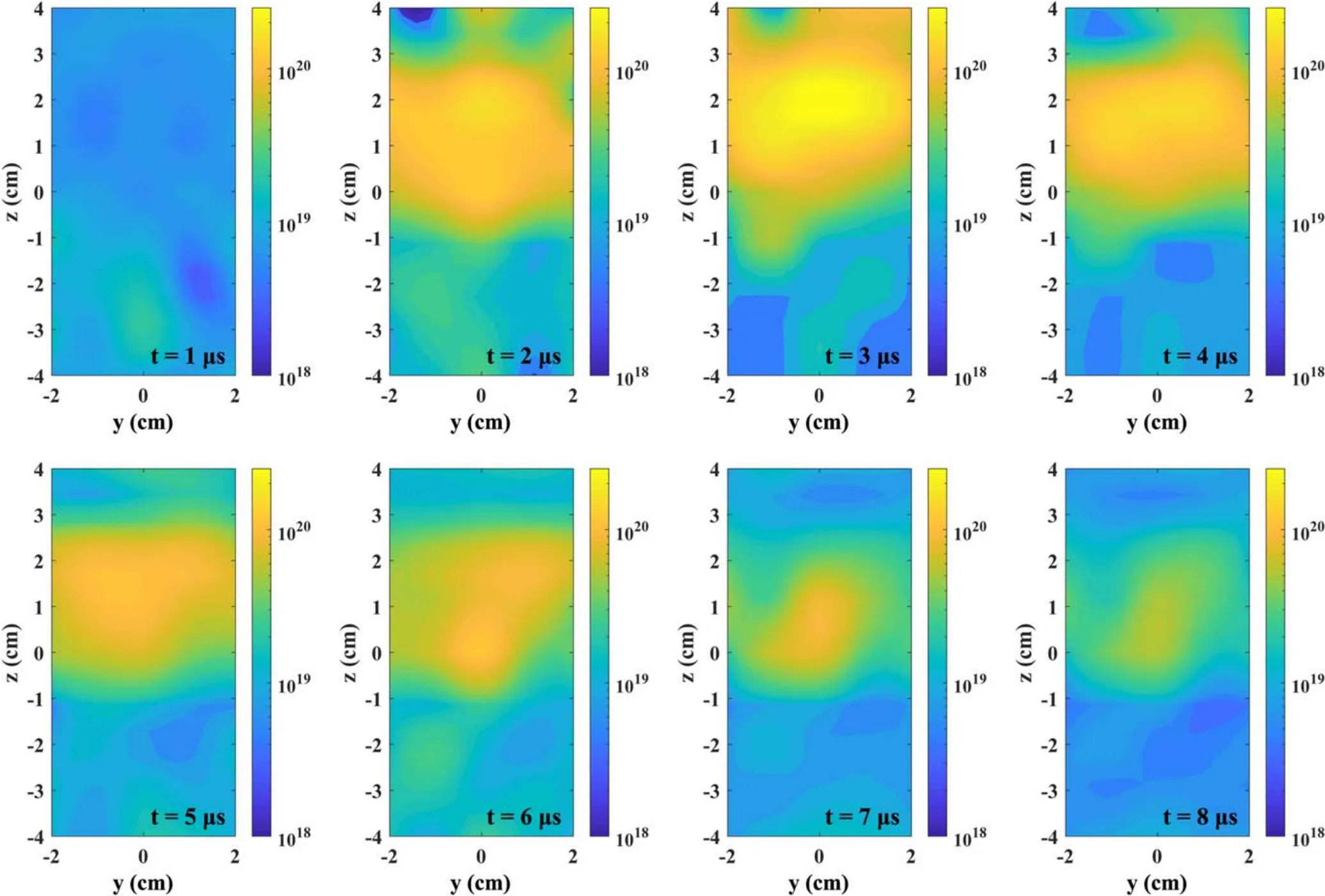
Figure 8.Electron density versus time along perpendicular y-z slices (x=4 cm).The unit for the electron density is m−3.The minimum scale is 1×10¹⁸ m−3,and the maximum scale is 2.5×10²⁰ m−3.The reference time t=0 is the beginning of the main discharge.Each y-z slice at every time step consists of measurements from 45 positions (5×9).
The 2D profiles can be generated by processing recorded data along a 2D plane in the experimental volume.Figure 7 shows the electron density over time along the central x-z plane.This is equivalent to a side view of the PPT,but without the interference of other planes(i.e.y ≠0 planes).In contrast,with line-integrated data from high-speed cameras and spectroscopic measurements,the recorded data corresponds to the sum of light emitted from all y planes within the line-of-sight.
In figure 7,we can clearly see the expansion of the plasma plume downstream with time.It is also possible to see the canting of the plasma plume towards the cathode (in the positive z-direction).This canting of the plasma plume is inherent to most PPTs with parallel electrodes,and has previously been proposed to be due to the depletion of ions near the anode,resulting in plasma instabilities in the initial current sheet [26,27].It is also apparent that recorded values along the x-axis centerline with y=0 and z=0 (as shown in figure 5)will fail to capture the global maxima due to canting of the plasma plume.The global maxima in figure 7 are approximately 50% to 75% higher than the maximum values along the centerline shown in figure 5.
We can also take 2D slices perpendicular to the downstream distance,i.e.along y-z planes at various downstream distances x.This is equivalent to a front view of the plasma plume (looking into the thruster’s exit),but without interference from other y-z planes.When an image is captured from the front of a PPT,all information regarding the depth of the structure into the page is lost.In contrast,figures 8 and 9 show 2D y-z slices from x=4 and 6 cm,respectively.Here,all of the depth information is preserved in addition to the temporal relationship,making it possible to completely isolate individual y-z planes.The canting of the plasma plume is also apparent,with the maximum electron density not manifesting at (y,z)=(0,0).This again shows that downstream measurements along the x-axis alone will not capture the region of maximum electron density.With the experimental PPT here,the true peak is located at approximately z=1 to 2 cm,depending on the downstream distance and the elapsed time.If measurements of the true peak values are required,it is relatively simple to perform 1D measurements at z > 0 along the z-axis in order to identify the canting of the plasma plume.This would enable the identification of the z location of the peak with minimal measurements.

Figure 9.Electron density versus time along perpendicular y-z slices (x=6 cm).The unit for the electron density is m−3.The minimum scale is 1×10¹⁸ m−3,and the maximum scale is 2.5×10²⁰ m−3.The reference time t=0 is the beginning of the main discharge.Each y-z slice at every time step consists of measurements from 45 positions (5×9).
While the overall maxima of the electron density are clearly located in the positive z-direction,at around t=1 μs after the beginning of the discharge,there is also the presence of a faint plasma plume in the negative z-direction(this can be seen faintly in the first image of figure 7).As the density of this negatively canted plume is much lower than the maxima of the positively canted plume,figure 10 shows x-z profiles of the 4 to 6 cm downstream region with different scale bars from t=0.6 to 1.2 μs in order to highlight this negatively canted plume.After approximately t=1.2 μs(the last image in figure 10),the positively canted plume associated with the maximum electron density arrives,vastly overshadowing the negatively canted plume by an order of magnitude (1019versus 1020m−3).The leading edge of the negatively canted plume arrives much earlier than the main plume (0.6 μs or earlier at 4 cm).To the best of our knowledge,this is the first identification of a fast-arriving negatively canted plasma plume from a PPT.At the present time,we are only able to hypothesize as to the origins of this negatively canted plume.One possible source may be from fast electrons originating from the PPT discharge.While the ions are canted towards the positive z-direction,the electrons should be similarly canted towards the negative z-direction.Further detailed studies will be necessary to clarify the physical origins of this plume.
Finally,using the recorded data,it is also possible to stack several 2D planes together to understand how the 3D structure of the plasma plume evolves with time,as shown in figure 11.Here,the canting of the plasma plume and the expansion of the plasma into vacuum are both clearly visible.It is also possible to observe the behavior of the plasma as it travels downstream and expands into vacuum.Data such as this can be used as a reference in the development of more complex PPT models in the future that consider plasma interactions.
We have demonstrated here how individual triple Langmuir probe measurements can be easily combined to obtain a visualization of the overall plasma behavior in the plasma plume of a PPT.Corresponding animated media for the figures here can be requested from the authors.It is also important to discuss some of the limitations and possible future improvements.
First,in terms of spatially distributed measurements such as those presented here,it is important to be aware of the limitations in the spatial resolution.While a three-axis translation stand can easily be operated with very small spatial intervals,there is no advantage in using intervals that are much smaller than the probe’s dimensions.The upper limit of the spatial resolution is dependent on the spatial interval(grid spacing),i.e.if a larger grid spacing is chosen,the spatial resolution will decrease.However,the lower limit of the spatial resolution is dependent on the dimensions of the triple Langmuir probe,as there is a finite distance between each electrode.This means that even if the grid spacing is decreased to an arbitrarily small value,the lower limit will still be dependent on the probe dimensions.

Figure 10.Electron density versus time along the central x-z slice where y=0.The unit for the electron density is m−3.The reference time t=0 is the beginning of the main discharge.The minimum scale is 1×10¹⁸ m−3,and the maximum scale is 2.5×10¹⁹ m−3.Each x-z slice at every time step consists of measurements from 27 positions(3×9).This highlights the appearance of a negatively canted plasma plume that arrives much earlier than the main plasma plume.The electron density of this negatively canted plume is an order of magnitude lower than that of the positively canted plume,which arrives after approximately t=1.2 μs.
Next,we should also consider the semi-quantitative nature of Langmuir probes mentioned in an earlier section.This limitation concerns all Langmuir probes when used with a PPT.The lack of detailed knowledge regarding the actual average ion mass and a suitable calibration system means that the plasma parameters calculated using the Langmuir probe equations are only estimates of the real plasma parameters,rather than direct measurements.While it is possible to calibrate Langmuir probes using a well-known plasma source,detailed information regarding the actual ion mass from the measurement target is still needed to improve the accuracy of the calculations.This is particularly important with PPTs due to the complex nature of the plasma and the non-elemental composition of typical propellants.Detailed analysis of the plasma composition using other methods such as spectroscopy may enlighten us regarding the actual ion distribution of the plasma plume,which can then in turn be used to improve probe measurements.Nevertheless,the semi-quantitative results here are still able to provide estimates of the plasma parameters,as well as identify the complex nature of the plasma plume,including regions of high electron density and the canting of the plasma plume.The mapping of Langmuir probe results thus serves as a simple way to quickly probe the nature of the plasma plume of a PPT.
5.Conclusions

Figure 11.Volumetric x-y-z visualization of the global electron density versus time.The unit for the electron density is m−3.The minimum scale is 1×10¹⁸ m−3,and the maximum scale is 2.5×10²⁰ m−3.The reference time t=0 is the beginning of the main discharge.Each x-y-z compilation at every time step consists of measurements from 270 positions (6×5×9).
We demonstrated here the use of a triple Langmuir probe in probing the plasma parameters of the transient microsecondduration plasma plume of a PPT.With advances in computing capabilities,data processing has become much easier than in the past,where the processing of individual data points alone would have been a much more extensive task.We show how individual measurements can be easily combined to give an overall spatiotemporal profile of the plasma plume.Typically,experiments are either performed using an arbitrary downstream location(a 0D measurement)or along the downstream axis(a 1D measurement).However,this is unlikely to capture the complex plasma physics that take place in the plasma plume.The plasma plume of a PPT is also known to be canted towards the cathode,and so measurements along the centerline will fail to capture the true maximum values of the plasma.We show that depending on the downstream distance,the experimental PPT used here exhibits the maximum electron density at around 1 to 2 cm above the centerline.The presence of two plasma peaks associated with each current pulse was also identified at 4 to 6 cm from the thruster’s exit.Further downstream,these two peaks were observed to merge into a single peak,meaning that downstream measurements will in fact capture the parameters of the combined pair.This is in line with previous suggestions that the PPT plume consists of a fast-moving peak followed by a much smaller slow-moving peak.We also identified a negatively canted plume of much lower density that arrives much earlier than the main positively canted plume.This may have been produced by negatively canted electrons originating from the discharge.The 2D and 3D data that can be obtained by combining individual Langmuir probe measurements are able to give us a better overall view of the plasma plume,and can also aid as a reference in the future development of more complex numerical PPT models.
Acknowledgments
This work was supported by National Natural Science Foundation of China(No.11802022)and the Beijing Institute of Technology Research Fund Program for Young Scholars.
 Plasma Science and Technology2020年9期
- Plasma Science and Technology的其它文章
- Impact of exterior electron emission on the self-sustaining margin of hollow cathode discharge
- Research on the neutralization control of the RF ion micropropulsion system for the‘Taiji-1’ satellite mission
- On the heating mechanism of electron cyclotron resonance thruster immerged in a non-uniform magnetic field
- Study on the influence of the discharge voltage on the ignition process of Hall thrusters
- The plume diagnostics of 30 cm ion thruster with an advanced plasma diagnostics system
- Performance of a 4 cm iodine-fueled radio frequency ion thruster