
Performance of a 4 cm iodine-fueled radio frequency ion thruster
2020-09-14 01:13JinghuaYANG杨景华ShaoxiaJIA贾少霞ZhenhuaZHANG张振华XinghuaZHANG张兴华TingJIN金婷LongLI李龙YongCAI蔡勇andJianCAI蔡建
Plasma Science and Technology 2020年9期
Jinghua YANG(杨景华),Shaoxia JIA(贾少霞),Zhenhua ZHANG(张振华),Xinghua ZHANG (张兴华),Ting JIN (金婷),Long LI (李龙),Yong CAI (蔡勇) and Jian CAI (蔡建)
1 Institute of Microelectronics,Chinese Academy of Sciences,Beijing 100029,People’s Republic of China
2 Nanjing University of Aeronautics and Astronautics,Nanjing 210016,People’s Republic of China
3 Suzhou Nano-Space Dynamics Technology Co.Ltd,Suzhou 215000,People’s Republic of China
Abstract
Keywords:electric propulsion,iodine propellant,radio frequency ion propulsion
1.Introduction
The rapid progress of micro-satellites has greatly promoted the development of micro-propulsion technology,and new requirements for micro-propulsion technology are put forward.In the last decade,Dressler et al[1]and Tverdokhlebov et al [2]proposed the concept of the electric propulsion technology based on a solid iodine propellant due to the problems of electric propulsion using xenon as a propellant.Although there is similar propulsion performance between the iodine and xenon propellant,using iodine instead of xenon has obvious advantages[3]:the storage density is about three times higher than that of xenon,one-fifth the price of xenon(iodine at 99.99% purity),and a low-pressure storage reservoir can be used,which will make the micro-propulsion system lightweight,with a small size and low cost.
Electric propulsion technology based on a solid iodine propellant has been attracting widespread attention [3-14].The American Busek Company [4-8]first used an iodine propellant in a BHT200 Hall thruster,and their research team successively developed BHT-600,BHT-1000,BHT-8000 and other Hall thrusters.Test results showed that the propulsive performance of iodine propellant is similar to that of the xenon propellant.Liu et al [10]studied the ignition of a cutting field thruster using iodine as the propellant,and the results showed that the discharge currents of the iodine propellant and xenon propellant are similar under the same experimental conditions.
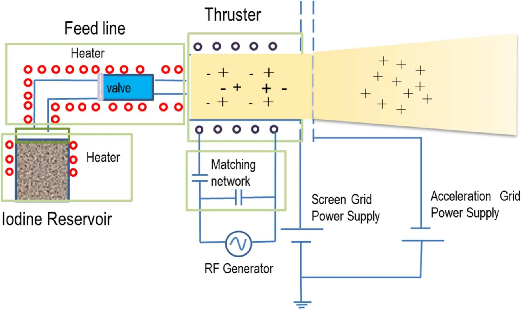
Figure 1.Conceptual view of an IRIT.

Figure 2.IRIT4 thruster and iodine discharge photos.
Unlike the immersion cathode of the Hall thruster,RF ion propulsion adopts the method of inductively coupled plasma(ICP) discharges [3,11-14],which is suitable for an iodine propellant due to the non-contact electrodes with the plasma.Tsay et al[3]studied the propulsion performance of the BIT-3 iodine RF ion thruster.Thrust and specific impulse were 1.35 mN and 3200 s respectively at the nominal power of 60 W,and there are slight differences of the thrust-to-power ratio between the iodine and xenon propellant.In the experiments of Holste et al [11],the radio-frequency DC power has been recoded as a function of mass flow with the iodine flow rates of 0.3-0.6 mg s−1and ion-beam currents of 80-95 mA.Their results showed that iodine exhibits the better performance at low mass flows,and the situation changes at higher mass flows where the performance of iodine is significantly poorer than that of xenon,and the reason may be related to the molecular nature of iodine.French P.Grondein et al [12]established a global model of radio frequency ion thruster of iodine propellant (frequency 13.56 MHz,6 cm chamber diameter),the results show that iodine has a similar performance compared to xenon,and when mass flow rate is lower than 1.3 mg s−1,iodine has a higher efficiency than xenon.
In this paper,the propulsion performance of the IRIT4 RF ion thruster using iodine as the propellant was studied experimentally.The experimental equipment and methods are described in section 2,the results and analyses are given in section 3.Finally,the main conclusions are summarized in section 4.
2.Experimental procedures
2.1.Experimental principle
The working principle of an iodine RF ion thruster (IRIT) is shown in figure 1.Solid iodine propellant stored in the lowpressure reservoir is heated to sublimate to a gaseous state,which is transferred into the thruster through the feed line and then ionized to generate plasma by the coil-induced electromagnetic field,finally the ions are accelerated and extracted by the grid electrode to generate the thrust.
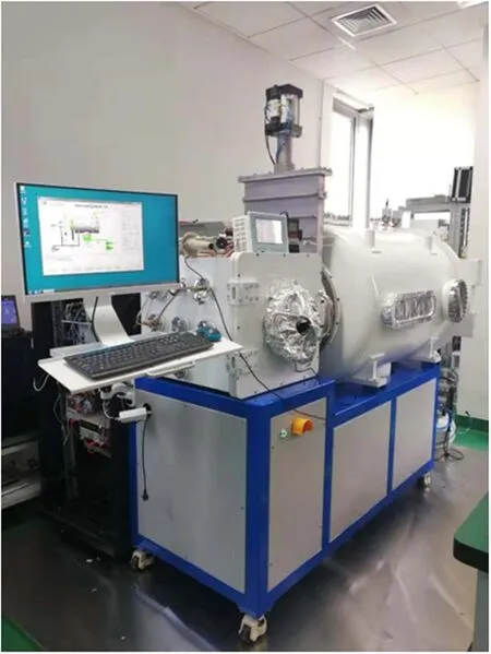
Figure 3.Photo of the vacuum system.
2.2.Thruster
An IRIT4 prototype with the double-gate structure (figure 2)was tested in the experiment.The discharge cavity of IRIT4 is 4 cm diameter,and 5 turns of helical copper coils are wound on it.The coils were energized by a low mega-hertz frequency of 1.995 MHz in this experiment.The 0-200 W RF power and 1-10 MHz frequency are adjustable using a customized RF power supply (RISHIGE RSK-K).The RF incident power(RFin),RF reflected power(RFre)and the working frequency could be measured by the Octiv Poly 2.0 VI probe which was manufactured by Impedans Ltd.The probe was connected between the RF generator and the RF matcher(capacitor matching network) by which the impedance matching between the RF generator and thruster could be achieved.
The thruster is equipped with two molybdenum grids.The first grid(screen grid)extracts the ions with the operating voltage range of 1000-1800 V.The second grid(acceleration grid) focuses and accelerates the ion beam,and its voltage is set to−200 V.The screen grid and the acceleration grid were respectively connected to two customized DC power supplies with adjustable voltages (South China Starlight Electronics Co.Ltd);the error of voltages and currents is within 1%.
2.3.Vacuum system

Figure 4.Mass flow rates of iodine at different reservoir temperatures.
The experiment was carried out in a two-stage vacuum system(figure 3) including a square cavity and a cylinder cavity isolated by a CF450 pneumatic flapper valve.The size of the square cavity in which the thruster is installed is 0.45×0.45×0.45 m3,and the size of the cylinder cavity as a main cavity is φ0.8 m×1.6 m.Two direct-connected oil rotary vane vacuum pumps of BSV40 and BSV60,a roots pump of BSJ70L,and a molecular pump of TYFB-3600 are used.The background neutral pressure could reach 5×10⁻⁵Pa,and the experimental temperature was room temperature.
2.4.Flow rate control method
In the experiment,the flow rate of xenon propellant was set to 1 sccm with the vacuum pressure about 1.6×10⁻³Pa;the flow rate of the iodine propellant was 100 μg s−1with the vacuum pressure 2×10⁻⁴Pa.The xenon flow rate was controlled by a flow controller of ALICAT with the flow rate range of 0-2 sccm and the flow rate accuracy of ±(0.8% of reading+0.2% of full-scale).
There are three main methods of the flow rate control of iodine propellant:reservoir temperature control [3],thermal throttling [5,7],and proportional flow control [4].The temperature control method for the iodine storage reservoir was used in the experiment.Pressure and flow rates in the feed lines are controlled indirectly by controlling the temperature of the reservoir,since the saturated vapor pressure of iodine is related to the temperature.Furthermore,the feed line temperature is set to be higher about 15°C than the reservoir temperature to prevent the iodine condensation.
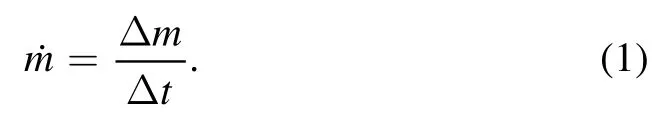
The average mass flow rate of iodine is obtained by a weighing method.The solid iodine storage reservoir is heated to a certain temperature Tc,the working time at this temperature point is recorded as Δt (more than one hour),the mass before and after the system working is weighed by an electronic balance with a measurement accuracy of 1 mg to obtain the mass loss Δm.The average mass flow rateis calculated by formula (1).Figure 4 shows the mass flow rates of iodine at different reservoir temperatures.The mass flow rate error is less than 10% by using this method.In this experiment,the temperature of the reservoir is controlled at 62.5 °C,and the corresponding mass flow of iodine is 100 μg s−1(curve-fitted data).
From the experimental results of Szabo et al [4],the response time is long and the discharge current oscillates violently when the reservoir temperature control method is used.However,the preliminary test in this paper showed that the flow rate of the iodine propellant and the ion-beam current of the RF ion thruster were relatively stable,and the time of heating the reservoir to reach certain stable temperature was about 30 min.
2.5.Performance data
The thrust values in the figures below were not directly measured from a thrust stand;it was calculated based on the measured ion-beam current in the experiments.This method has a typical accuracy of 95% when comparing to actual thrust stand measurements [3].
The extracted ion-beam current Ibin milliamps is defined as the ion current extracted directly from the plasma Iscr(indicated by the milliammeter of screen grid power supply)minus the ion current flowing on the acceleration grid Iacc(indicated by the milliammeter of acceleration grid power supply) [11].

Ion-beam currentsIbat a certain iodine mass flow rateare obtained,and then the thrust F and the impulseIspfor a two-grid ion thruster with singly-charged monatomic ions are shown in formula (3) and (4) [3].

whereVsis the screen grid voltage,miis the ion mass,and q is the proton charge.However,formula(3)does not include any thrust loss due to beam divergence,when considering a typical 15°half-angle beam divergence,the ion-beam current Ibshould be multiplied by the beam divergence factor of 0.966(cos15°).In fact,the beam divergence half-angle would be smaller for a well-designed gridded ion thruster.
3.Experimental results and discussions
3.1.Performance of the thruster with iodine propellant under continuous operation
Performance of the thruster was tested continually for eight hours,with the iodine mass flow rate of 100 μg s−1,the radio frequency load power of 35 W and the screen grid voltage of 1800 V.The beam currents at different RF load powers from 18 W to 47 W were recorded at the 4th hour(t1),6th hour(t2)and 8th hour (t3),and the thrust and specific impulse results with RF load power and total thruster power are shown in figure 5,where DCinrepresents the input grid DC power,and then the expressions(RFin−RFre)and(DCin+RFin−RFre)are defined as the RF load power PRFand the total thruster power PDrespectively.
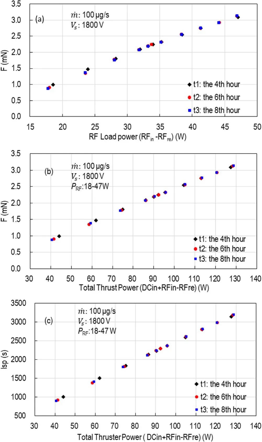
Figure 5.Performance of the thruster with iodine propellant under continuous operation ((a) thrust versus RF load power;(b) thrust versus total thruster power;(c) specific impulse versus total thruster power).
It can be seen from figure 5 that the data curves obtained at the three time moments almost coincide,which indicates that the propulsion performance is stable.With the increase of the RF load power from 18 W to 47 W,the total thrust power increasing from 40.6 W to 128.8 W correspondingly,the thrust F and specific impulse Ispvary from 0.88 mN to 3.13 mN and 893 s to 3190 s respectively.At the nominal RF load power of 35 W (corresponding total thruster power of 95.8 W),the thrust of 2.32 mN,the specific impulse Ispof 2361 s and the thrust-to-power ratio of 24.2 mN kW−1are obtained.
At the thrust power of 120 W the thrust-to-power ratio 24.2 mN kW−1is higher than the 22.5 mN kW−1with BIT3[11];however,the impulse 2900 s is much lower than the 3500 s of BIT3,which represents the lower propellant utilization.Based on the propellant utilization which is defined as beam ion over total particle flux((mi/q)·(Ib/)),the way to solve the problem is to increase the extracted ion current and improve the ionization efficiency while maintaining a higher thrust-to-power ratio.The preliminary test results show that reducing the gap between two grids could obviously improve the extracted ion current.Besides,it is necessary to research the thruster performance at different mass flows to find the optimized ionization efficiency in future research.

Figure 6.Performance of the thruster with iodine propellant at different screen grid voltages ((a) thrust versus RF load power;(b)thrust versus total thruster power;(c)specific impulse versus total thruster power).
3.2.Performance of the thruster with an iodine propellant at different screen grid voltages
Figure 6 shows the propulsion performance of the iodine propellant at three screen grid voltages (1000 V,1500 V and 1800 V),the iodine mass flow rate of 100 μg s−1and RF load power from 18 W to 47 W.It can be seen that total thrust power,the thrust and specific impulse have the same trend with the decreasing screen grid voltage while keeping the same RF load power setting.
Reducing the screen grid voltages from 1800 V to 1500 V and 1000 V at RF load power of 35 W,total thruster power is reduced from 95.8 W to 82.4 W and 63.4 W,the thrust is reduced from 2.32 mN to 1.98 mN and 1.45 mN,and the specific impulse is also reduced from 2361 s to 2021 s and 1477 s.
At the screen grid voltages of 1800 V and 1500 V,the thrust-to-power ratios of them are relatively closer in the entire total thruster power range,which are 24.2 and 24.0 mN kW−1respectively.When the voltage decreases to 1000 V,the thrustto-power ratio is reduced to 22.7 mN kW−1,which was possible due to the mismatch of the ionization rate and the ion extraction rate.In fact,the ion current density offered by the discharge plasma depend on RF power and mass flow rates[14],which means that the same RF load power and iodine flow rate would produce the same ion current at the same grid electrode parameters.However,according to the Child-Langmuir law,lower screen voltages limit maximum draw ion current capability from the grid system (fixed gate structure parameters) [12],and furthermore,maximum extracted ion current obtained by space-charged Child-Langmuir law needs to be further corrected by impingement-limited perveance when acceleration grid currents rise above 5% of the screen current [13].In fact,the results in the experiment also show that the acceleration grid currents at the voltage of 1000 V increase with increasing RF load power;and it is about 13%of the screen current at the RF load power of 47 W.Therefore,although lower voltage of power supply is preferable to improve the reliability in application of the satellite,proper screen voltage should be determined to ensure the higher thrust-to-power ratio and specific impulse.
3.3.Comparison of performance between iodine and xenon propulsion
The propulsive performance of iodine propellant and xenon propellant is compared at the screen voltage of 1800 V and the RF load power from 18 W to 45 W.The xenon flow rate is 1 sccm,and the corresponding mass flow rate is about 98 μg s−1,which is closer to the 100 μg s−1iodine mass flow rate.
Figure 7 shows the thrust and specific impulse of iodine propellant and xenon propellant at different powers.Data points obtained by those two propellants are much closer.At the same RF load power and screen grid voltage,the propulsion performance of iodine propellant and xenon propellant is comparable,which is consistent with the results given by Tsay et al [3]and Liu et al [10].
A difference between iodine and xenon can be seen from figure 7 that,the iodine thrust is slightly higher than xenon at a higher RF load power,but it is slightly lower than xenon at a lower RF load power,the RF load power at the cross point is about 25 W (corresponding total thruster power of 62 W).At the nominal 35 W RF load power,the thrusts of them are 2.32 mN and 2.15 mN respectively,and the thrust-to-power ratios of them are 24.2 mN kW−1and 23.5 mN kW−1respectively.This trend is consistent with the simulation results that the thrust F of iodine propellant is slightly higher than that of xenon propellant at higher RF power [12].Since both of them have the same grid and power parameters,this may be related to the molecular characteristics of them,which result in different ion current density offered by the discharge plasma (relevant to the plasma density,electron temperature and ion mass)[14],and the further analysis to the problem is in the next paragraph.
Although iodine has a lower ionization energy 10.5 eV for atomic and 9.40 eV for molecular iodine than the 12.1 eV for xenon,but iodine is diatomic,it has additional energy loss such as dissociation energy(1.567 eV).In addition,the initial pressure in the discharge chamber is higher for xenon than for iodine at the same neutral gas flow rate,which represents a higher ionization frequency [12].Therefore,at the lower RF load power condition the plasma density of xenon may be higher than iodine;but at the higher RF load power,almost the same amount of I+as Xe+may be obtained,and a small amount of I2+may also be included.Another influencing factor may be that higher RF load power would result in the higher electron temperature for iodine than that for xenon.Further research on the iodine plasma characteristic should be studied.

Figure 7.Comparison of propulsion performance between iodine and xenon ((a) thrust versus RF load power;(b) thrust versus total thruster power;(c) specific impulse versus total thruster power).
4.Conclusions
A 4 cm diameter RF ion thrust prototype fueled by the solid iodine propellant is developed successfully and the experiment results are presented.The test results show that the thrust and specific impulse by using iodine as a propellant are 0.88-3.13 mN and 893-3190 s at the flow rate of 100 μg s−1,the screen grid voltage of 1800 V and the total thruster power of 40.6-128.8 W,the power level of which could be satisfied in the application for the micro-satellites(the bus power lower than 200 W provided by about 100 kg micro-satellites,considering about 70% secondary power efficiency).What is more,the iodine propellant shows the almost similar performance compared to the xenon propellant,together with its solid-state and low-cost characteristics,which would greatly extend the application capabilities of micro-satellites in the future.
In addition,preliminary experimental results show that the thrust reduces as the mass flow rate of iodine decreases,but the specific impulse improves greatly.In future study,in order to better meet application demand of micro-satellites for high specific impulse and high thrust-to-power ratio,performance of the IRIT4 at the different iodine mass flow rates needs to be studied systematically to get the more detailed results at wide flow rate range.
Acknowledgments
The financial support from National Natural Science Foundation of China (No.11805265) and Key Laboratory of Micro-Satellites,Chinese Academy of Sciences (No.KFKT201903) is gratefully acknowledged.
猜你喜欢
汽车实用技术(2022年14期)2022-07-30
美与时代·美术学刊(2022年3期)2022-04-27
华人时刊(2021年17期)2021-11-12
民间故事选刊·上(2019年9期)2019-09-24
金沙江文艺(2019年7期)2019-07-29
故事会(2019年8期)2019-04-20
金沙江文艺(2017年4期)2017-03-31
椰城(2014年6期)2014-11-17
天津诗人(2014年3期)2014-05-29
天池小小说(2009年7期)2009-08-06
 Plasma Science and Technology2020年9期
- Plasma Science and Technology的其它文章
- Impact of exterior electron emission on the self-sustaining margin of hollow cathode discharge
- Research on the neutralization control of the RF ion micropropulsion system for the‘Taiji-1’ satellite mission
- On the heating mechanism of electron cyclotron resonance thruster immerged in a non-uniform magnetic field
- Study on the influence of the discharge voltage on the ignition process of Hall thrusters
- The plume diagnostics of 30 cm ion thruster with an advanced plasma diagnostics system
- Experimental investigation on the plasma morphology of ablative pulsed plasma thruster with tongue-shaped and flared electrodes