
Guidance Control for Parallel Parking Tasks
2020-02-29 14:22:08JiyuanTanChunlingXuLiLiFeiYueWangDongpuCaoandLingxiLiSenior
Jiyuan Tan,, Chunling Xu, Li Li,, Fei-Yue Wang,,Dongpu Cao,, and Lingxi Li, Senior
Abstract—Parking into small berths remains difficult for unskilled drivers. Researchers had proposed different automatic parking systems to solve this problem. The first kind of strategies(called parking trajectory planning) designs a detailed reference trajectory that links the start and ending points of a special parking task and let the vehicle track this reference trajectory so as to park into the berth. The second kind of strategies (called guidance control) just characterizes several regimes of driving actions as well as the important switching points in certain rule style and let the vehicle follows the pre-selected series of actions so as to park into the berth. Parking guidance control is simpler than parking trajectory planning. However, no studies thoroughly validated parking guidance control before. In this paper, a new automatic parking method is presented, which could characterize the desired control actions directly. Then the feasibility is examined carefully. Tests show that a simple parking guidance control strategy can work in most parallel parking tasks, if the available parking berth is not too small. This finding helps to build more concise automatic parking systems that can efficiently guide human drivers.
I. INTRODUCTION
IF being compared with car-following, parallel parking often appears more difficult for drivers, since drivers not only need to drive backward but also move laterally. As a result,good driver assistance systems and automatic parking systems are expected by many drivers, because machines can help handle this hot potato for human beings [1]-[8].
Researchers proposed several automatic parking systems in the last three decades. The first kind of strategies is usually called as parking trajectory planning. The key idea is to design a detailed reference trajectory along which the vehicle can move and park into the berth [9]-[11]. Conventionally, there are two major difficulties in implementing this kind of strategies. First, vehicles are not moving robots which can steer freely. It is hard to appropriately consider the dynamic constraints of vehicles in trajectory planning stage. Usually,dynamic constraints are addressed indirectly as the curvature constraints of the reference trajectory. However, the errors may make it unable to implement the planned control actions.Second, we can add a certain feedback controller according to the gap between the reference parking trajectory and the actual one, reshaping the steering actions and making the vehicle roughly track this reference trajectory. However, the design and implementation costs of a proper feedback controller are high. Moreover, the whole strategy consists of two-stages. If the first stage gives the wrong solution, there is no chance to correct it in the second stage.
Differently, a new trajectory planning method is proposed in[12], [13]. Suppose we have shifted the starting point to the origin point, this trajectory planning method samples all the possible steering actions and the corresponding trajectories as well as the resulting ending points of the trajectories. Then, a deep neural network is used to store the relation between steering actions, trajectories, and ending points in a reverse manner. That is, this deep neural network accepts ending points as input and outputs the corresponding steering actions and trajectories. When a new parking berth (ending point) is given, it directly recalls the required steering actions and trajectories that can move the vehicle toward this parking berth (ending point). This new approach greatly simplifies the parking planning problem but still consumes relatively high computational time and storage resources.
The second kind of strategies is called parking guidance control. Its key idea is to characterize several regimes of driving actions as well as some important switching points in certain rule style. Then, we let the vehicle follow the preselected series of actions so as to park into the berth.However, no studies thoroughly validated parking guidance control before. The so-called “ parking guidance control”proposed before are focus on the technical assistant systems to help drivers to find parking space, while not the control strategies or control rules [14], [15].
Most known guidance control rules were empirically summarized by skilled human drivers. These rules are usually very concise and thus make the resulting guidance control simple to understand and execute. Many drivers claimed that these guidance control rules are helpful. However, no studies thoroughly validated parking guidance control before.
In this paper, we carefully examine its feasibility by applying the sampling and testing framework proposed in[13]. Tests show that a simple parking guidance control strategy can work in most parallel parking tasks, if the available parking berth is not too small. This finding helps to build more concise automatic parking systems that could well communicate with drivers to provide efficient guidance rules.
To better present our findings, the rest of this paper is arranged as follows. Section II presents the parking guidance control for a general parallel parking scenario and explains how to check its feasibility. Section III provides some numerical testing results to verify the effectiveness of this method. Finally, Section IV concludes the paper.
II. PROBLEM PRESENTATION AND THE RSS STRATEGY
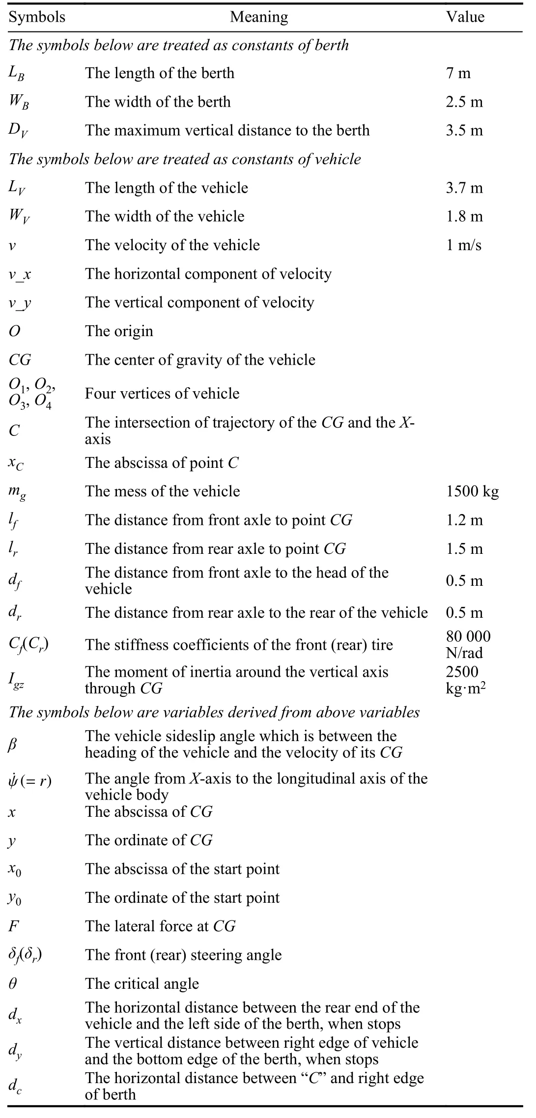
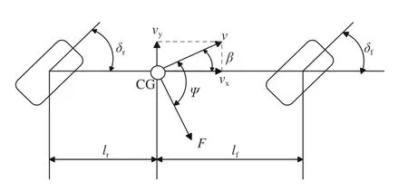
The parking scenario studied in this paper is shown in Fig. 1 and the related symbols are listed in Appendix.
The origin of the world coordinate is set as the outer boundary point of the left berth. TheX-axis is parallel to the road and points to the right.
In this paper, we introduce a simple three-step guidance control strategy which is the most popular in Chinese driving schools. As shown in Fig. 1, the core of this strategy can be summarized as follows:
Step 1:Straightly drive the vehicle from the initial position(IP) forward to the start position (SP) whose coordinate is (x0,y0) and make the angleψfrom theX-axis to the longitudinal axis of vehicle becomes approximately 0;
Step 2:Drive the vehicle backward to the critical angle position (CAP) from SP with full right turn (setting steering angleδf) with the velocityv, until the angleψfrom theX-axis to the longitudinal axis of vehicle reaches the preselected critical angle position (CAP) (ψ=θ);
Step 3:Drive the vehicle backward from CAP with full left turn (setting steering angle -δf) with the velocityv, until the vehicle arrives the final position (FP) in the berth (meanwhile the angleψfrom theX-axis to the longitudinal axis of vehicle becomes approximately 0).
There are five controlling variables in this three-step guidance control strategy:x0,y0,δf,v, andθ. Given the lengthLBand widthWBof the berth as well as the maximum vertical distanceDVto the berth, we need to examine whether there exists an appropriate setting of these five variables to make the above three-step parking feasible.
For a given set of {x0,y0,δf,v,θ}, we can use the vehicle dynamic model presented in Appendix I to simulate the corresponding vehicle trajectory. There are three situations that this trajectory becomes infeasible:
1) The right front cornerO1of the vehicle collides with the boundary of the right berth. Fig. 1 denotes this situation as the right yellow star.
Let us denote the intersection of theX-axis and the trajectory of the center of the gravity (CG) as point “C”. The horizontal distance between “C” and the right edge of the berth of interest is denoted asdc. Clearly,dcreaches its maximum value when the vehicle is parallel to the berth. So,to avoid colliding with the boundary of the right berth, we require the abscissaxcof point C to satisfy


2) The vehicle collided with the bottom edge of the berth.
Let us denote the horizontal distancedYbetween the rear end of the vehicle and the left side of the berth, when the vehicle stops. Clearly, we requiredYto satisfy

3) The rear end of the vehicle collides with the left side of the berth.
Let us denote the horizontal distancedXbetween the rear end of the vehicle and the left side of the berth, when the vehicle stops. Clearly, we requiredYto satisfy

The verification of the determined parking process could be straightforward. Fig. 2 shows an example trajectory, wherex0= 8.2 m,y0= 1.4 m,δf= 38°,v= 1 m/s,θ= 54°. The values of all the other parameters are given in Appendix I. We can see that the guidance control makes the vehicle park into the berth without causing any collisions.

The parameters of a vehicle’s dynamic model can be predetermined. So, the maximum allowable steering angleδfcan be known in advance. If we further set the velocityv, there are only three variables that characterize the proposed control actions. First, the choice of the start point {x0,y0}. Second, the choice of the critical angle positionθ. To derive a simple parking guidance rule that can be easily used in practice, the following study will focus on finding an appropriate start point as well as the critical angle positionθto make the above guidance control feasible.
III. TESTING RESULTS
In this section, we will first show that there will exist a lot of combinations of {x0,y0,θ} are feasible, if the berth is not too small and the maximum allowable steering angleδfis large enough. Second, we will derive a simple rule to choose{x0,y0} according to the length of the berth. Third, we will show how to select an appropriateθ, with respect the given{x0,y0} and steering angleδf.
In practice, the width of the berth is usually large enough.So, we focus on the influence of the length of the berth. As presented in [5], we can enumerate all the possible parking trajectories that a vehicle can make under the given combination of {x0,y0,θ}. Since the solution space of {x0,y0,θ} is continuous, we will use the sampling techniques, say,with the discretization time interval as 0.1 s, the discretization spatial interval as 0.1 m for {x0,y0}, and 1° forθ. Considering the dynamic attribute of current cars, we allowδf∈[30°,40°]andθ∈[0°,90°]. Fig. 3 gives an example the feasible region of {x0,y0}, where all the other parameters are chosen in Appendix expect keeping the lengthLBof the berth variable.According to practices, we choose theLBchange from 3.0 m to 9.0 m, with the discretization distance interval as 0.5 m.Surprisingly, we can always find an appropriate combination of {x0,y0} with the correspondingly calculatedδfandθ, if the length of the berth is at least 0.3 m larger than the length of the vehicle. Further tests show that the width of the berth has little influence on the parking feasibility, if it is wider than the vehicle; while the length of the berth has a significantly stronger influence.
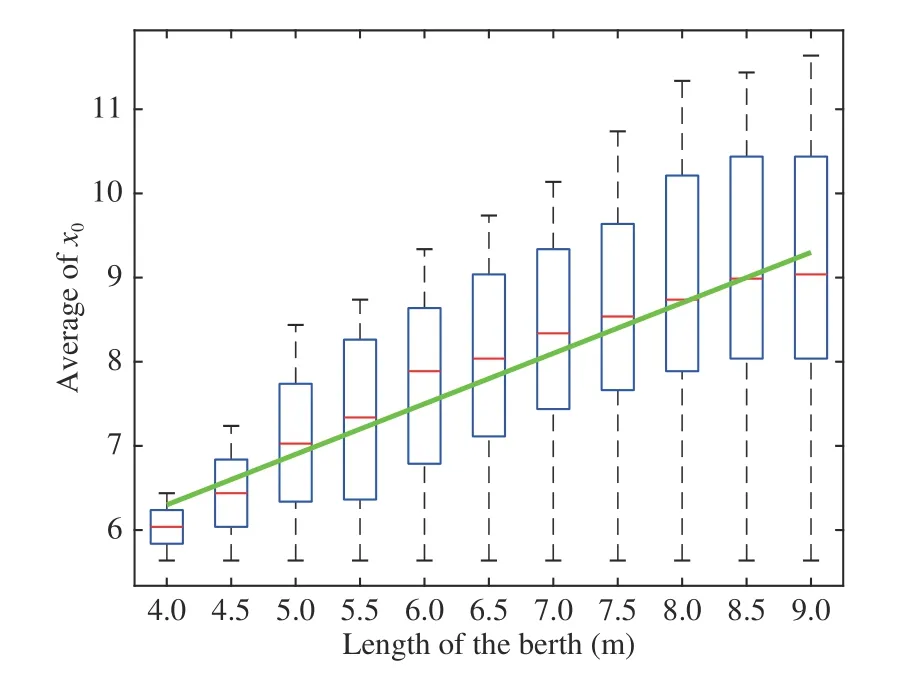
WhenLB>4.0 m, the average allowable value ofy0increases slowly from 1.3 m, asLBincreases. It soon reaches a saturation value as about 1.4 m. This indicates that we could roughlyy0as a constant in parking guidance control with respect the given dynamic parameters of vehicles. Moreover,the average allowable value ofx0increase noticeably from 5.6 m, asLBincreases. Furthermore, there was an obvious upper limit ofx0for eachLB, say, the vehicle could not park successfully when it is too far from the berth.
Based on these results, we can establish a simple determination rule of the abscissax0of the starting point as

for the given parameter sets of the vehicle.
Further testing results show that we can always find such simple a determination rule to calculate the SP when other types of vehicle are considered (with different sets of parameters).
Finally, we can set up a determination rule to selectδfandθ,with the given Starting Point calculated from (4). We still use the discretization sampling technique to enumerate all the possible combination of {δf,θ}. Tests suggest that, if we chooseδf= 35°, the critical angleθcan be simply chosen as

to park the vehicle.
In summary, the rules (4) and (5) for determining the controlling variables are quite simple. This enables us to carry out such parking guidance control on intelligent vehicles.
IV. CONCLUSION
This paper has presented a new automatic parking method.Different from existing methods, this new method characterizes the desired control actions directly, rather than seeking the desired trajectory first. Moreover, the series of whole control actions are divided into three steps which can be explicitly characterized and easily applied. Such three-step control strategy is indeed a direct imitation of a human parking procedure which is popularly taught in Chinese driving schools.
Several simple rules are found to determine the exact values of the control parameters for the proposed guidance control,when the dynamic parameters of the vehicle are given. Testing results show that this simple guidance control method works well, if the available parking berth is not too small. This finding indicates that skilled human drivers had summarized an effective solution for parallel parking tasks. Furthermore,we can also design more concise automatic parking systems.
Since the control rules are proposed by human, we can view this approach as a special hybrid-augmented intelligence application [16], [17]. In the future, we will further analyze how to integrate human driving experience so as to build more intelligent vehicles.
APPENDIX VEHICLE DYNAMICS MODEL
In this paper, the dynamic model of vehicle is adopted from[18], [19], and the nomenclatures used in this paper are given in Table I. As shown in Fig. 4, the reference point center of the gravity (CG) is chosen at the center of gravity of the vehicle body. Its coordinate vale (x,y) represents the position of the vehicle. Vehicle velocityvis defined at the reference point CG. Heading angleψrefers to the angle from theX-axis to the longitudinal axis of the vehicle body. slide-slip angleβis the angle from the longitudinal axis of the vehicle body to the direction of the vehicle velocity.
When moving forward, the movement of the vehicle can be described as
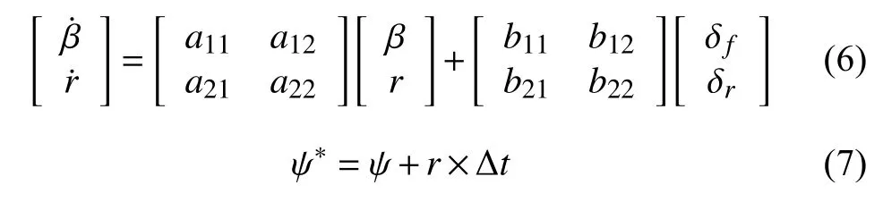
where
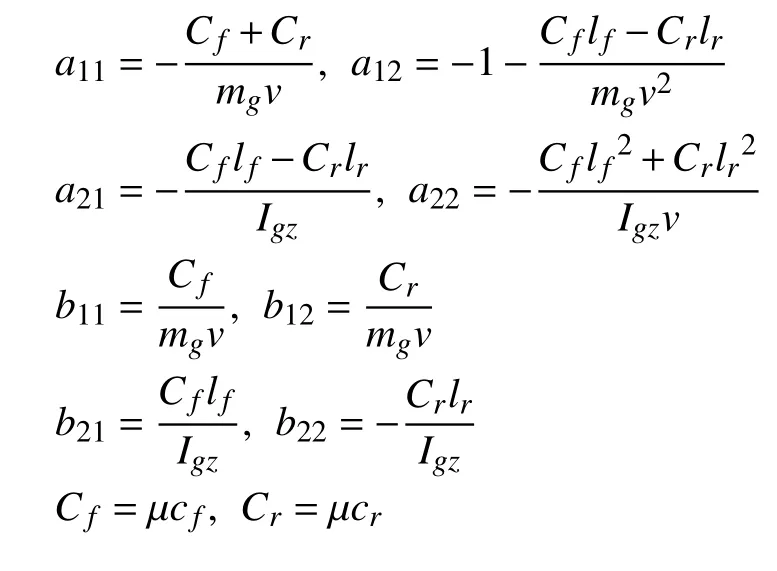
whereμis a weighting coefficient with dry roadμ= 1 and wet roadμ= 0.5.
When moving backward, the movement of the vehicle can be described as
where

We can then get the movement of vehicle in worldcoordinate. For instance, when moving backward, the velocity of vehicle can be calculated as

and the position coordinates are

ACKNOWLEDGMENT
We would like to thank Mr. Chenghong Wang, who is the Vice-Chairman of Chinese Association of Automation, for his insightful opinion to improve this paper.
 IEEE/CAA Journal of Automatica Sinica2020年1期
- IEEE/CAA Journal of Automatica Sinica的其它文章
- Event-Triggered Sliding Mode Control for Trajectory Tracking of Nonlinear Systems
- Distributed Adaptive Cooperative Tracking of Uncertain Nonlinear Fractional-order Multi-agent Systems
- A Self-Organizing RBF Neural Network Based on Distance Concentration Immune Algorithm
- A New Fire Detection Method Using a Multi-Expert System Based on Color Dispersion, Similarity and Centroid Motion in Indoor Environment
- Novel Stability Criteria for Sampled-Data Systems With Variable Sampling Periods
- Robust Control of a Bevel-Tip Needle for Medical Interventional Procedures