Influence mechanism of machining angles on force induced error and their selection in five axis bullnose end milling
Zerun ZHU, Fngyu PENG, Rong YAN, Zepeng LI, Jiwei WU,Xiowei TANG, Chen CHEN
a School of Mechanical Science and Engineering, Huazhong University of Science and Technology, Wuhan 430074, China
b State Key Laboratory of Digital Manufacturing Equipment and Technology, Huazhong University of Science and Technology,Wuhan 430074, China
KEYWORDS Force induced error;Five axis machining;Machining efficiency;Machining angles;Milling;Optimization
Abstract In the machining of complicated surfaces, the cutters with large length/diameter ratios are used widely and the deformation of the machining system is one of the principal error sources.During the process planning stage,the cutting direction angle,the cutter lead and tilt angles are usually optimized to minimize the force induced error. It may lead to a low machining efficiency for bullnose end mills,as the material removal rates are different largely for different machining angles.In this paper,the influence mechanism of the machining angles on the force induced error is studied based on the models of the instantaneous cutting force when the cutter flute traveling through the cutting contact point and the stiffness of the machining system.In order to evaluate the machining angles, the force induced error/efficiency indicator (FEI) is defined as the division of the force induced error and the equal volume sphere of the removed material. FEI is dimensionless, with the lower FEI,the lower force induced error and the higher machining efficiency.For optimal selection of the machining angles,the critical FEI is calculated with the constraint of force induced error and the desired material removal rate,and the critical FEI separate the set of the machining angles into two subsets.After the feed rate scheduling process,the machining angles in the optimal subset would have higher machining accuracy and efficiency,while the machining angles in the other subset have lower machining accuracy and efficiency. Through the machining experiment of five axis machining and freeform surface machining, the effectiveness and superiority of the proposed FEI method is verified with a bullnose end mill, which can improve the machining efficiency with the constraint of force induced error.
1. Introduction
Five-axis end milling is widely used in the machining of turbines, propellers, aircraft landing gears, and other parts with complicated surface in the aerospace industry. To avoid interference of the tool/workpiece and improve the machining efficiency,the bullnose end mills with large length/diameter ratios are utilized. With the action of cutting force, these tools are prone to deformation,which will greatly restrict the machining accuracy and efficiency of the related parts.1In addition, due to the gap between machining process modeling and CAM technology,2the processing parameter selection and the tool path optimization strategy are still facing challenges. In CIRP Annals, Altintas et al.3reviewed the machining process model and emphasized that the models of the mental cutting process need to be integrated into the geometric model.
The optimization of the tool path and feed rate by controlling the cutting force is an effective way to improve the accuracy in 3-axis finishing machining. For a better surface machining,Lim and Menq4maximized the feed rate by selecting the cutting direction with a minimal cutting force and force induced error,and designed a surface machining control strategy that the tool path was generated on the reconstructed surface considering the form error. Feng and Su5developed an integrated optimization method for the cutting direction and feed rate of the ball end mills in the inclined plane finishing process, fulfilled the best machining efficiency under the constraint of machining error.For 3-axis machining,Lacalle et al.6optimized the overall cutting direction of the surface with the minimum average cutting force,then the local cutting direction for each grid point is calculated by the minimum deformation force.
For 5-axis finishing machining,the influence of the tool orientation on the force induced error is considered additionally during the optimization process.In order to reduce the surface forming error, Lacalle et al.6selected the tool orientation and the cutting direction with the deformation force in the threshold of the cutting force.Geng et al.7distinguished the minimal deformation force of different tool orientations, and acquired the optimal tool orientation in the condition that only the cutter flute in the ball end region was in cutting. Koike et al.8planed the sequence of material removal and optimized the cutting directions and tool orientations by minimizing the deflection of the workpiece, during which the static cutting force was adopted.Ozturk et al.9investigated the cutting force,surface form error and stability of different tool lead angles and tilt angles, the results show that the influence of tool orientation on cutting geometry,cutting force and dynamic characteristics is huge and nonlinear.Later,Budak10improved the cutting parameters by studying the cutting force and forming error of the ball end mills with different lead angles and tilt angles.
Many contributions about the surface machining tool path optimization strategy including the effects of the force induced error was verified with a good result for ball end mills. For instance, Lazoglu et al.11presented a method to generate the tool path with the minimal cutting force, which was validated in the free form surface ball end milling process. In order to improve the processing efficiency under the constraint of machining error, Xu and Tang12developed a force-area entropy potential field method to generate the tool path and optimize the feed rate for ball end mills.Ma et al.13utilized the constraint of force fluctuation to plan the tool path of curved surface parts, but which was limited to 3 axis machining. Considering the machining stability, the torque, the spindle power, the deformation of the cutter and the surface roughness, Tunc et al.14studied the 5-axis machining strategies and the cutting parameters selection method. Last year, Tunc15developed an automatic tool path modification method in 5-axis machining based on process simulations covering roughing, semi-finishing and finishing.In these studies, the problem was only approached for ball end mills, for bullnose end mills there still remain relatively unknown to practitioners. Considering the effect of initial residual stress-induced deformation and finishing allowanceinduced deformation, Li et al.16proposed a finishing allowance allocation strategy to reduce the overall machining deformation of large thin-walled components. Considering the maximum cutting force and the feasible range of the cutter orientation angles, a five axis flank milling tool path was generated with a continuity curvature and smooth cutting force17.
During the process planning stage, the cutting direction angle, the cutter lead and tilt angles are usually optimized to minimize the force induced error in the past works, but it may lead to low machining efficiency for bullnose end mills.As shown in Fig. 1(a), (b), (c), for different cutting direction angles of a saddle surface,the maximum cutting widths signed with aeuand aevare determined by the direction curvature of the cross cutting direction. As shown in Fig. 1 (d), (e), (f), for different cutter lead and tilt angles of bullnose end mills, the shape of the cutter/workpiece engagement (CWE) and the maximum cutting widths signed with aeLand aeTare different largely. Considering the fact that the cutting forces are determined by the undeformed chip thickness and the cutter/workpiece engagement18, these machining angles have great influence on the cutting force for bullnose end mills.Wu et al.19optimized the cutter orientation and tool paths for machining the impeller section. Gdula20increased the accuracy of fiveaxis machining of complex surfaces by controlling the lead angle.Recently, Duan et al.21,22researched the effect of cutter lead and tilt angles on the force induced deflection of bullnose end mills and the force induced error of propeller surface machining. For some machining angles, the force induced error of the machined surface is small but the machining efficiency is low.
Aiming at this problem, the effect of machining angles on force induced error, these machining angles evaluation and optimization method for bullnose end mills are described and proposed in this paper, and the contributions are:
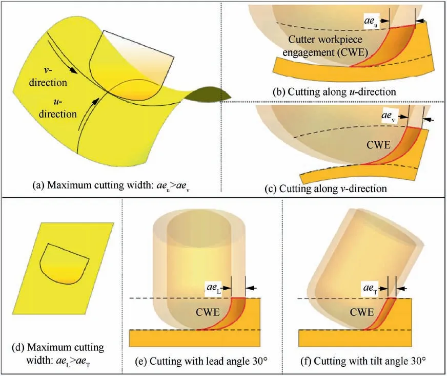
Fig. 1 The maximum cutting width and CWE for different machining angles of bullnose end mills with the same scallop height.
1) The influence mechanism of the machining angles on the force induced error is described with the models of the coordinate relationship among the five axis freeform surface machining,the instantaneous cutting force when the cutter flute traveling through the cutting contact point and the stiffness of the machining system.
2) The force induced error/efficiency indicator (FEI) is defined as the division by the force induced error and the equal volume sphere,and used to describe the tradeoff relationship between the force induced error and the machining efficiency for different machining angles in the bullnose end milling.
3) The desired material removal rate and the force induced error are utilized to calculate the critical FEI,which separates the set of the machining angles into two subsets.The machining angles in the optimal subset would have a higher machining accuracy and efficiency, while the machining angles in the other subset have lower machining accuracy and efficiency.
4) A feed rate scheduling method is proposed with the constraints of the force induced error, in order to give full play to the advantages of the machining angles in the optimal subset and maximizing the machining efficiency in finish machining.
The remainder of this paper was structured as follows. In Section 2.1, three machining angles were utilized to describe the coordinate relationship in the freeform surface machining.Based on the five axis cutting force model and the machine tool stiffness model considering the cutter deflection,in Section 2.2,the force induced error for freeform surface machining and FEI was proposed to evaluate the machining angles. In Section 3.1 and 3.2, FEI was calculated and the evaluation and classification method of the machining angles was developed,the force induced error constraint was fulfilled by scheduling the feed rate in Section 3.3.The simulation analysis and experimental verification were conducted with plane and surface machining in Section 4. The entire study was summarized and conclusions were drawn in Section 5.
2. Influence mechanism of machining angles on force induced error
The coordinate transformation of the freeform surface machining is described with three machining angles, the feed direction angle, the lead angle and the tilt angle. Based on these parameters, the force induced error is calculated based on the cutting force and the machining system stiffness models,and the FEI is proposed to address the tradeoff relationship between the force induced error and the machining efficiency of bullnose end mills.
2.1. Descriptions of the surface machining angles
2.1.1. Feed direction angle


Fig. 2 Transformation between WCS and FCN.
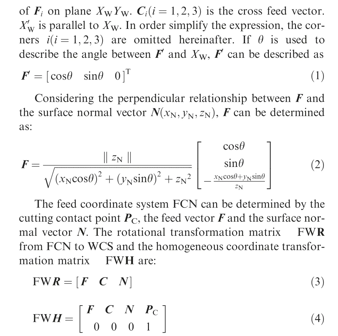
with C=N×F, in which F, C and N are unit vectors and represent the direction vectors of the coordinate axis X, Y and Z in FCN.
2.1.2. Cutter orientation angles


2.2. Force induced error and FEI in the surface machining
In the surface machining, the cutting forces induced deformation is time varying and has immediate influence on the machining accuracy and quality.In order to evaluate the force induced error, as shown in Fig. 4, the following formula is derived6in which, Q is the material removal rate, which is defined as ae×ap×f(ae: cutting width, ap: cutting depth, f: feed rate)for 3-axis machining, and calculated through the method in reference24for bull end mills 5-axis machining.


Fig. 3 Transformations between FCN and TCS.
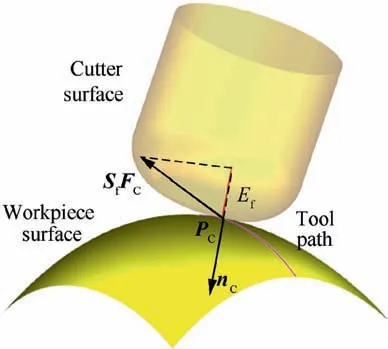
Fig. 4 Schematic of force induced error.
FEI is a dimensionless index.For a specific combination of machining angles defined in Section 2.1,when an equal volume material is removed, the larger FEI, and the greater the force induced error is.In other words,when the same force induced error occurs, the machining efficiency is lower with a larger FEI, and the relevant machining angles should be avoided.Opposite,the machining efficiency is larger with a smaller indicator, and the relevant machining angles should be selected.
Here FEI is defined through normalizing the force induced error by the equal volume sphere of MRR, this is mainly due to the following two reasons: (1) constitute the tradeoff relationship between the force induced error and the machining efficiency for different machining angles, which is used to find the machining angles that can not only remove a lot of materials but also ensure the machining accuracy; (2) make FEI show weaker correlation with feed rate than machining angles,this is beneficial to feed rate scheduling after selecting the machining angles in Section 3.3.
3. FEI based evaluation and selection of machining angles
For a cutting contact point on the surface, the calculation method of FEI for different machining angles is described and the set of FEI,the sets of feed direction and cutter orientation angles are proposed. FEI based classification method is developed to acquire the set with high machining efficiency under the constraint of the force induced error. The force induced error constraint is realized by feed rate scheduling to ensure the maximum efficiency of the specific machining angles.

Fig. 5 Schematic of force induced error/efficiency indicator.
3.1. FEI of machining angles for a cutting contact point
For a particular point on the surface, three angles are used to describe the potential cutting patterns, which are the feed direction angle θ, the lead angle θL, and the tilt angle θT, as defined in Section 2.1. For a cutting contact point, the sets of these parameters are shown in Eqs. (10)-(13).


After setting other machining parameters (the scallop height,the cutting depth, the feed per tooth, etc.) and the cutter parameters (the diameter, the fillet radius, the helix angle,etc.), the cutting force is predicted through the model in Appendix A. Considering the force induced deformation of the machine tool and the cutter, the equivalent static stiffness of the machining system end is calculated in Appendix B.Then, the force induced error of the machined surface is simulated and the FEI is evaluated with the model proposed in Section 2.2. The flow chart of the FEI for different machining angles is shown in Fig. 6.


Fig. 6 FEI evaluation chart for feed directions and cutter orientations on a specific cutting contact point.

3.2. Evaluation and classification of machining angles

3.3. Realization of force induced error constraint
Recently, Yang et al.25proposed a feed rate scheduling algorithm to constrain the form errors caused by the cutting load disturbances. By adjusting feed rate, Altintas et al.26validated that the force induced tool path tracking and contour errors can be constrained with the desired tolerance of the part.Wang et al.27developed a feed rate scheduling method to quickly solve the appropriate feedrate under constant peak cutting force. Referring to Feng’s method5, the feed rate scheduling process is conducted through Eq.(20) with constraint of the force induced error Ecritical:


During the scheduling process, the maximum feed rete fmaxis set with constrains of the cutter and the machine tool.For a fast convergence, the initial feed rate is set as fmaxand the adjustment step Δf is set as 0.5fmaxat the first cycle, while in the follows, when the sign of E0-Ecriticalat the present cycle is opposite to the last cycle, the adjustment step Δf is changed to its half 0.5Δf.
4. Analysis and case study
In order to illustrate the optimization process of five-axis machining strategy and validate the effectiveness the proposed method,analyses of the plane surface machining with different cutter lead angles and tilt angles are implemented and validated with machining experiment.A case study of the freeform surface machining experiment indicate that it is success to improve the machining efficiency and reduce the force induced error by optimizing the machining strategies with FEI.
4.1. Analysis and experimental verification of five axis machining
A plane is a special surface that has same properties in different directions.And its machining characteristics are same without regard to the anisotropy of the machine tool. In this section,plane cutting simulations and experiments are utilized to analyze and verify the relationship between FEI and machining efficiency under the constraint of force induced error.
4.1.1. Simulation analysis
During the simulation process, the cutter parameters and the cutting parameters in the simulation are shown in Table 1.For plane machining, without regard to the anisotropy of the machine tool, the feed direction angle can be left out and the cutter orientation angles are analysis here. In order to get the relationship between FEI and the machining efficiency of various tool orientations, the simulations are conducted with the lead angle from 4° to 17°and the tilt angle from -20° to 20°. The set Aθ,θL,θTcan be simplified as the set AθL,θTand expressed as

Table 1 Cutter parameters and cutting parameters of the simulation process.

With feed rates increasing from very small to large, the mechanism of cutting force changes from friction to shear.28The shear force is proportional to the feed rate and the friction force is not. For a relatively high feed rate, the force induced error is proportional to Q like the shear force to the feed rate,it works well for selecting the machining angles first and scheduling the feed rate then. For a relatively low feed rate,the force induced error is no longer proportional to Q, at this time, the FEI is higher, the machining efficiency is lower, and the corresponding machining strategies should not be selected.Here, we focus on the set partition method of the machining angles and the proposed FEI is suitable for this purpose.
4.1.2. Experimental verification
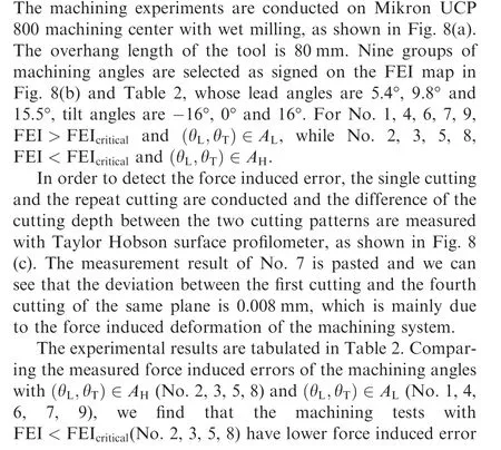
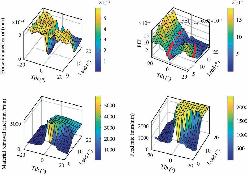
Fig. 7 Simulation results of force induced error, FEI, material removal rate and feed rate with various cutter orientations.

Fig. 8 Verification experiments.

Table 2 Machining parameters and the experimental results.

In addition,for FEI >FEIcritical(No.1,4,6,7,9),the measuring force induced errors are from 0.0052 mm to 0.009 mm,and those are larger than the constraint value 0.005 mm. The deviations are mainly due to the errors of the measurement system and the machine tool stiffness. While for FEI <FEIcritical(No. 2, 3, 5, 8), the corresponding force induced error are lower than the constraint value 0.005 mm,and the material removal rates of the machining angles in the optimal subset are larger 4-40 times than these in the other subset. The results validate that the proposed FEI based machining angles selection method is effective to improve the machining efficiency during the finishing milling process with constraint of the force induced error.
4.2.Analysis and experimental verification of surface machining
A case study of freeform surface machining is presented in this section to validate the effectiveness of FEI based machining angles evaluation and optimization method considering the different of principle curvature of the surface and cutter orientations.
4.2.1. Surface model and analysis
The parametric surface model in the case study is given in Eq.(23). The surface is characterized by saddle surface and concave surface,as shown in Fig.9,these features are widely used in the propeller surface.

where, A represent the size of the surface in u- and v- directions, B adjust of altitude intercept of the surface in u- and v- directions, C describe the magnitude of the sine function in u-direction, D regulate the magnitude of the linear function in u-direction, E and F regulate the magnitude of the circular contour in v-direction. Values are as follows A=80,B=0.01, C=3, D=3, E=0.5, F=0.75.
Cutter parameters and partial cutting parameters are shown in Table 3, the spindle speed is 2000 r/min, the scallop height is 0.004 mm and the cutting depth is 1.3 mm.In order to get the FEI map with various cutting directions and tool orientations for machining the surface, the simulations are conducted with u- from 0.1 to 0.9 and v- from 0.1 to 0.7, the feed angle from 0° to 360°, the lead angle from 4° to 20° and the tilt angle from -20° to 20°. The set Aθ,θL,θTof machining angles is expressed as


Fig. 9 Parametric surface feature.

Table 3 Cutter parameters and cutting parameters for the parametric surface machining.

During the feed rate scheduling process, the force induced error is constrained to 0.01 mm and the maximum feed rate is set as 1800 mm/min. The initial feed rate is set as 800 mm/min, and the scheduling results are shown in Fig. 10. As we can see from Fig.10(a),the optimized feed rate for the strategy 1 is 1800 mm/min, which is the maximum feed rate and imply that the force induced error is lower than 0.01 mm. Meanwhile, the optimized feed rate for the strategy 2 is around 1050 mm/min as seen from Fig. 10(b).
4.2.2. Experimental verification

Fig. 10 Feed rate optimization result.

Fig. 11 Experimental site and the machined surface.

Table 4 Measured results of the surface machining errors.
The machining experiments are conducted on Mikron UCP800 five axis machining center, as shown in Fig. 11(a), the coolant is opening during the machining. Both tool paths are conducted with 2 times respectively and the machined surface are shown in Fig.11(b).After each set of cutting is completed,the surface machining error is measured with RENISHAW contact type in-machine inspection device. By using the inmachine measurement, the influence of geometry error can be partially shielded, and the error caused by the deformation of the process system can be highlighted.
The measured results are shown in Table 4, as we can see,the average machining time of two machining tests of strategy 1 is 163 s, and that of strategy 2 is 1137.5 s, while the average machining error of two machining tests of strategy 1 is 0.0058 mm, and that of strategy 2 is 0.0248 mm. The machining efficiency is improved 7 times and the machining error is reduced. These show that the presented force induced error based free-form surface machining strategies evaluation and optimization method is effective to improve the machining efficiency and reduce the force induced error.
5. Conclusions
On the machining of complicated surfaces, the cutters with large length/diameter ratios are used widely and show weak stiffness. For a better machining accuracy and efficiency, the influence mechanism of machining angles on force induced error is studied, the machining process optimization method considering the force induced error and the material removal rate is presented in this work. The conclusions are as follows.
1) Three machining angles, the feed direction angle, the lead angle and the tilt angle, are utilized to describe the machining strategy of a specific cutting point on the surface. The force induced error simulation method for freeform surface machining is described with the instantaneous cutting force when the cutter flute traveling through the cutting contact point and the stiffness of the machining system.
2) FEI is defined as the division of the force induced error and the equal volume sphere of the removed material,and used to evaluate these machining angles. The lower FEI, the lower force induced error of the machined surface and the higher machining efficiency.
3) The critical FEI is calculated with the desired material removal rate and the force induced error, and separates the set of the machining angles into two subsets. After the feed rate scheduling process with the constraint of force induced error,the machining angles in the optimal subset would have higher machining accuracy and efficiency.
4) The five axis machining experiment validates that the machining angles in the optimal subset have higher material removal rate than these in the other subset(4-40 times), at the same time, have the lower force induced error.
5) The results of the freeform surface machining experiment indicate that it is a success to improve the machining efficiency 7 times and reduce the force induced error by optimizing the machining strategies with FEI.
Based on the proposed evaluation and optimization method of machining angles involving cutting direction angle and cutter orientation angles, next research will be tool path planning of complicated surface finishing machining for optimal force induced error and higher machining efficiency. In addition,considering the scene of weak stiffness in the machining system,the method in this paper can be promoted to robot machining and has great potential to improve the machining efficiency with the force induced error constraint.
Acknowledgement
This research has been supported by National Science Fund for Distinguished Young Scholars of China (No. 51625502);Innovative Group Project of National Natural Science Foundation of China (No. 51721092); Innovative Group Project of Hubei Province of China (No. 2017CFA003).
Appendix. A 5-axis cutting force model
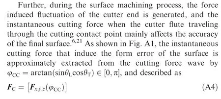
During the tool path planning process, in order to obtain the 5-aixs cutting force and to determine the cutting direction and the tool orientation quickly, the algebraic cutting force model29was adopted based on the parametric chip thickness model30and validated for bullnose end mills.23The symbolically solvable cutting contact boundary model is proposed23to predict 5-axis cutting force,which is described with the tool path parameters like the lead angle, the tilt angle, the cutting depth, and the path interval. The method is summarized as follows:

where f represents the feed per tooth, θLis the lead angle. Pφand Pκare the parameters to predict cutting forces, and expressed as follows:


Fig. A1 Cutting force wave and instantaneous cutting force when cutter flute traveling through cutting contact point.

whereKr, Kt, and Kaare the cutting force coefficients in the radial, tangential, and axial directions, φ and κare the cutter contact angles of the edge element in the radial and axial directions,dz is the axial discrete element length.z1,jand z2,jare the upper and lower limits of the j-th in-cutting edge and can be calculated rapidly through the symbolically solvable cutting contact boundary model as described in Fig. A1.
Appendix B. Static flexibility of machining system


where WTR= FTR WFR is a rotational transformation matrix form WCS to TCS,Strepresents the static flexibility of the cutting tool end. For the machining with a large length/diameter cutter, the static flexibility of the machining system is equal to that of the cutting tool end, thus Sf=St.
 CHINESE JOURNAL OF AERONAUTICS2020年12期
- CHINESE JOURNAL OF AERONAUTICS的其它文章
- ACKNOWLEDGEMENTS TO REVIEWERS(2020)
- SUBJECT INDEX OF CHINESE JOURNAL OF AERONAUTICS (2020)
- Improved local amplification factor transport equation for stationary crossflow instability in subsonic and transonic flows
- Simulation of multi-axis grinding considering runout based on envelope theory
- Resistance welding of glass fiber reinforced thermoplastic composite: Experimental investigation and process parameter optimization
- Coating deposition regularity depended on orientation difference in PS-PVD plasma jet
