
Deformation, fragmentation and acceleration of a controlled fragmentation charge casing
2019-11-18 02:34:48AndreasHelteOlofAnderssonPatrikLundberg
Defence Technology 2019年5期
Andreas Helte, Olof Andersson, Patrik Lundberg
FOI, Defence and Security, Systems and Technology, SE-164 90 Stockholm, Sweden
Keywords:Controlled fragmentation Fracture mechanics LS-DYNA Impetus
ABSTRACT Two different finite element software,LS-DYNA and Impetus,have been evaluated to test their ability to predict the deformation,fragmentation and acceleration of a controlled fragmentation charge casing.The general-purpose program LS-DYNA was used with a multi-material ALE formulation and a masspreserving erosion criterion coupled to a Johnson-Cook fracture criterion. In the Impetus simulations,a third order Lagrangian element formulation was used for the casing and a node-splitting element erosion treatment coupled to a Cockcroft-Latham failure criterion was used to describe casing fracture.The high-explosive gases were described by a discrete particle formalism.In order to acquire data to validate our computational tools and constitutive models, a series of experiments have been performed using a laboratory charge with an internal grooved casing. In the test series,the charge geometry was fixed except that the groove depth were varied from very shallow to very deep resulting in different deformation patterns, fracture modes and terminal velocities. Various diagnostic tools captured the different stages of the expansion and fragmentation of the casing.A high-speed framing camera depicted the deformation pattern before fragmentation and was used to determine the moment when the casing failed. Three different complementary techniques were used to follow the acceleration of the fragments; a Photon Doppler velocimetry to determine the initial acceleration of the casing, double exposed radiographs to estimate the fragment velocity after break-up and a high-speed video to determine the terminal velocity of the fragment after leaving the fireball. In addition, the fragments were soft recovered in a set of sawdust pit tests and their final shape and weight were measured.A SEM was used to characterise the fracture surfaces and to determine the modus of fracture(tensile or shear failure).Comparisons to experiments show that both software can predict the change in deformation behaviour when the groove depth increases,from tangential necking for shallow grooves to radial punching for deep groves. Both software could also reasonable well predict the acceleration of the fragments, though both overestimates the terminal velocity for the charge with the deepest grooves.
1. Introduction
The terminal velocity of the fragments from a natural fragmenting charge is mainly given by the Gurney energy (a characteristic parameter for each explosive) and the mass relation between the casing and the explosive [1]. By combining high explosives with thin and ductile casings, fragment velocities well above 2 km/s can be achieved. The drawback with natural fragmentation is that the shapes and sizes of the fragments will be more or less random which will limit the usability of the charge.
A widely used method to control the shape and size of the fragments is to use controlled fragmentation technology [2].Possible techniques are either related to micro-design of the material properties of the casing or by using some type of macrogeometrical effects. Examples from the literature are, e.g., a periodic variation of case strength made by laser hardening or chemical nitriding in a predefined pattern[3]or the use of a perforated liner between the casing and the explosive[4].A more direct method to control the fragmentation process is to make geometrical imprints(grooves) on the inside or outside of the charge casing [5,6]. This method is simple but the size and depth of the grooves may have a strong influence on the breakup time of the casing,thus,it will both affect the final shape of the fragments and their terminal velocity[7].
In this paper, the influence of groove depth on the breakup of the casing,the post acceleration of the fragments after breakup and the terminal velocity of the fragments has been studied.A series of experiments have been performed using a laboratory charge with an internal grooved casing. In the test series, the charge geometry was fixed except that the groove depths were varied from shallow to deep resulting in different deformation patterns,fracture modes and terminal velocities.
Several different diagnostic tools (flash X-rays, photon doppler velocimetry, a high speed framing camera and high speed video cameras)were used to capture the different stages of the expansion and fragmentation of the casing. In addition, the fragments were soft recovered in a set of sawdust pit tests and final shape and weight was measured. A scanning electron microscope (SEM) was used to characterise the fracture surfaces of the fragments and to determine the modus of fracture (tensile or shear failure). The experimental data was used to validate two computational tools,the finite element software LS-DYNA[8]and Impetus[9]and their ability to simulate the fragmentation process.
2. Material and methods
2.1. Test charge
The casing material was S355J2H,a ferritic non-alloy structural steel. The material were delivered as a hot-rolled seamless tube with outer diameter 63.5 mm and wall thickness 8 mm. The tubes had been normalized for 5 min at 870e900℃. According to the manufactures specification, the yield stress is RP0.2¼412 MPa, ultimate tensile strength Rm¼542 MPa (two tests according to EN ISO 6892-1830)and the energy absorbed in a Charpy impact test is 89 J (two tests according to EN ISO 148-1).
The tubes were first machined to smooth casings by turning them to a height of 147 mm, outer diameter 60 mm and wall thickness 3 mm.The internal groves were then cut in two opposite 30°spiral patterns.The shaping tool was V-shaped with an opening angle of 60°and had a tip radius of 0.25±0.03 mm. Four different groove depths were machined: 2.0 mm, 1.0 mm, 0.5 mm and 0.25 mm. This created an internal scoring pattern with 11 full height rows where each row contained 12 diamond shaped fragments. Additional, the upper and lower row contained 12 half diamonds each.In total,the casing contains 132 full diamonds and 24 half diamonds.
Melt cast hexotol (Comp-B, MIL-C-401 Grade A) from Eurenco Bofors (NSK 16) was used as main HE filler. The casings were first primed by a very thin layer of two-component polyurethane lacquer,Temadur Clear 55138,mixed with 10%TNT.The charges were melt-casted in ambient atmosphere using standard techniques and the obtained density was 1.67 g/cm3.An 8 mm diameter and 10 mm deep hole was drilled in the HE to achieve good contact with the detonator,Exel MS.A 5 mm thick steel cover with a concentric hole was positioned on top of the charge to provide confinement and for positioning the detonator. The bottom of the charges were not confined in order to minimize leakage of detonation products that could obscure the optical registrations. Fig.1 shows a photo and a drawing of the complete charge and details of the grooves in the casing.
2.2. Time resolved fragmentation and acceleration diagnostics
The evolution of the casing deformation was captured by a highspeed framing camera (HSFC). The approximate break-up time when the detonation products begin to leak through the cracks in the casing could also be deduced from the picture sequence.Three different techniques were used to measure the velocity of the casing and the final fragments;Photon Doppler velocimetry (PDV)to determine the initial acceleration of the casing, double exposed radiographs (X-ray) to estimate fragment velocity after breakup and a high-speed video(HSV)to determine the terminal velocity of the fragment after leaving the fireball. The test set-up is shown in Fig.2.All presented times are relatively to the time of initiation of the charge.
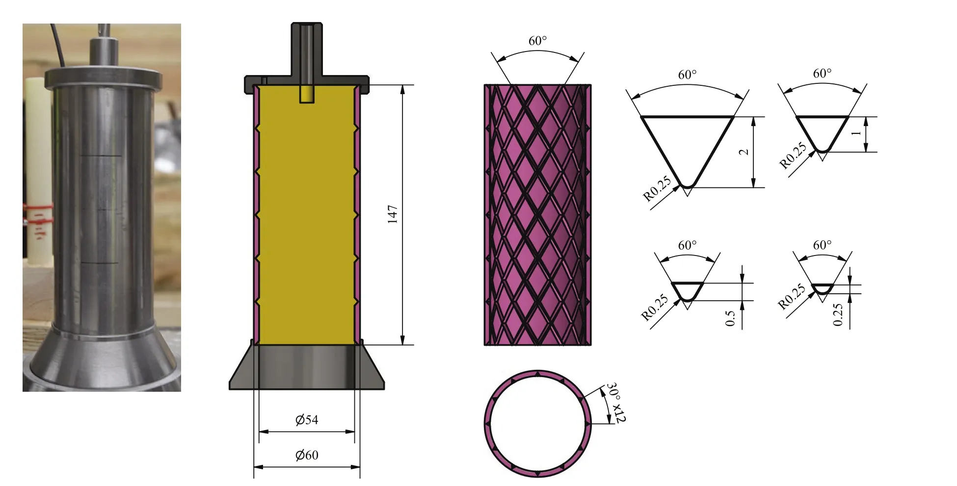
Fig.1. Photo of a complete charge (cover, casing and stand) and a planar section of the charge showing the groove pattern and the shapes of the different groove depths used:2.0 mm,1.0 mm, 0.5 mm and 0.25 mm.

Fig. 2. Positions and view directions of HSFC, X-ray tubes, PDV-probe and HSV.
The HSFC was a PCO hsfc pro digital framing camera,which is a four-channel image intensified camera with a resolution of 1280 pixels ×1024 pixels. The HSFC is placed at a distance of 4 m from the charge and looks at the charge via a mirror. An objective with focal length of 800 mm were used to get close enough to the charge.The charge was illuminated by an argon flash bomb.
Three 150 kV Scandiflash X-ray tubes were directed to opposite sides of the charge,one pair at the right side to evaluate the velocity at a late stage when the casing is fully fragmented and a single tube at the other side to observe the initial stage of the fragmentation.The flashes were situated 1.55 m from the charge. An X-ray sensitive image plate was placed 0.45 m behind the charge and was protected from the fragments by a steel block. The average fragment velocity at fully developed fragmentation was determined from the radiographs by measuring the distance between the centre of mass of each fragment in the two exposures and dividing the distance by the time difference (typically 35 ms). The exact timing of the flashes was adapted to the type of charge tested.
Initial fragment acceleration was measured by a two channel PDV-system from IDIL. Both probes were directed against the centre of the same fragment but at different angles, one perpendicular to the casings surface and the other with an angle of 6°to the surface (estimated velocity direction).
Two Photron SA-5 high-speed video cameras was used in the experiment.One was used to determine the terminal velocity of the fragment at the distance 1.2 me1.5 m from the charge. The other was used to determine the time when the fragments left the fireball. The fragments were illuminated by a second, time delayed,argon flash bomb.
Due to the geometry of the charge, there are two alternating fragment columns where one, denoted A, contains six full diamonds and one, denoted B, contains five full and two half diamonds. The different diagnostic tools were tracking slightly different fragments. The HSFC, X-ray and PDV were looking at column A while the HSV was looking at column B.The enumeration of the different fragments is depicted in Fig. 3. The PDV was tracking the acceleration of fragment 3 in column A. Velocity evaluation from the X-rays were done for fragments 1e4 in column A and from the HSV for fragments 2e5 in column B where edge effects were least prominent.
2.3. Fragment analysis
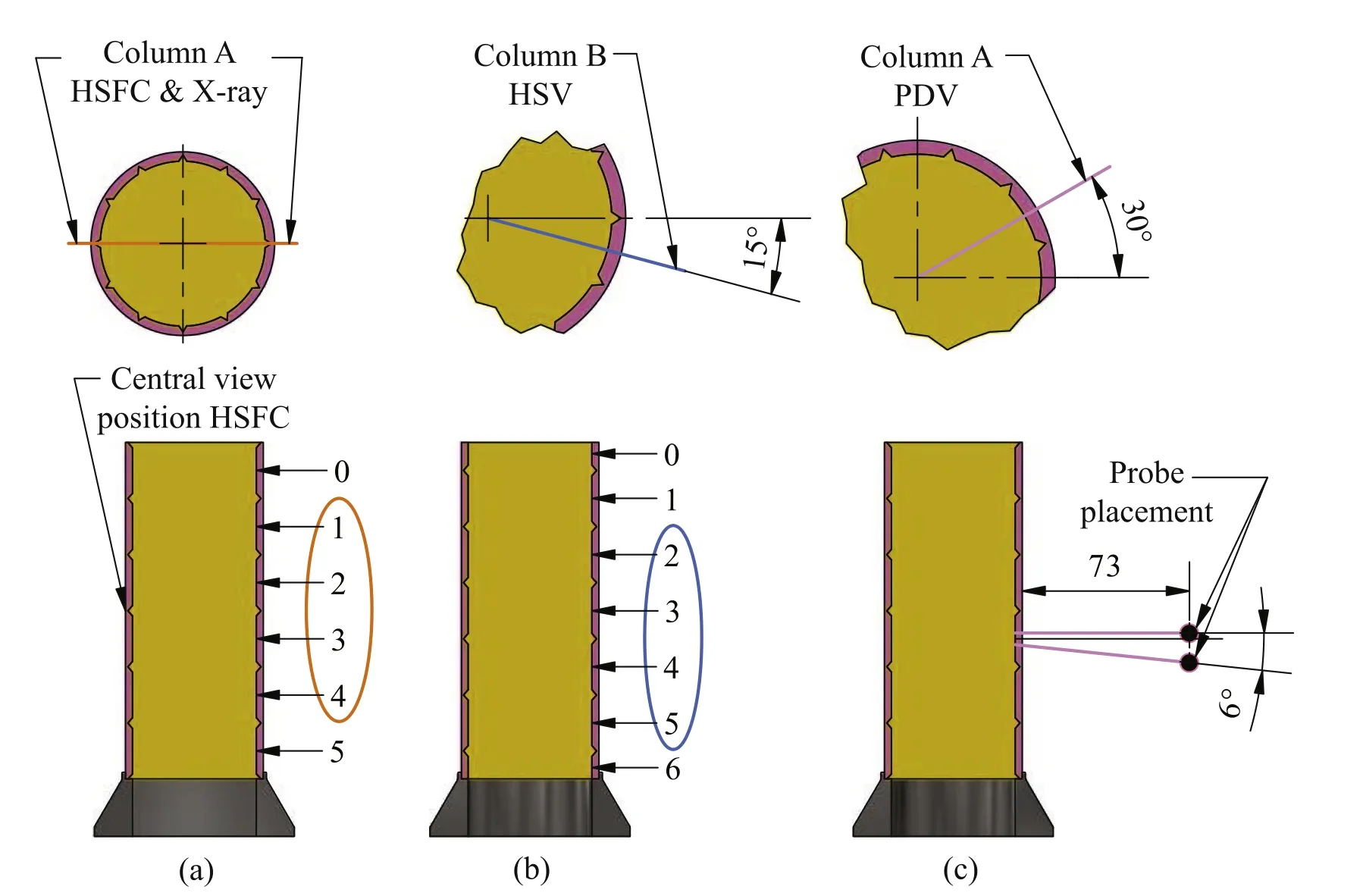
Fig. 3. Position of fragments used for registration by: (a) HSFC and X-ray, (b) HSV and (c) PDV.
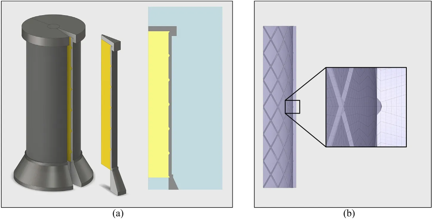
Fig.4. Computational models of a charge with groove depth of 0.5 mm for(a)LS-DYNA showing sector modelled and computational domain and(b)Impetus(the HE particles are not shown in the Impetus model).
In order to determine fragment distribution and perform post analysis of fragment deformation and fracture surfaces,one charge of each type were tested in a sawdust pit where the fragments were soft-caught by the sawdust. The charge was placed on a block of lightweight plastic foam and surrounded by an air volume to allow free expansion of the casing before hitting the sawdust. The sawdust and fragments were then separated from each other by a magnetic trap. The fragment were weighed and sorted in appropriate fractions with the help of an automated scale. The accuracy of the scale is within ±0.005 g. One fragment from each type of casing was then analysed with regard to the fracture surfaces and deformation. Phase content, grain size and dominant deformation mechanisms were analysed by means of so-called “electron backscatter diffraction”(EBSD)and the fracture surfaces were examined by SEM.
2.4. Numerical simulations
The two different finite element programs that have been evaluated were LS-DYNA from Livermore Software Technology Corporation (LSTC) and Impetus from Impetus Afea. LS-DYNA is a general-purpose FE software with a large selection of material models and different element formulations, e.g. pure Lagrangian,multi-material arbitrary Lagrangian-Eulerian (MMALE), smooth particle hydrodynamics(SPH)and discrete element spheres(DES).Impetus is a relatively new FE software specialized in defence applications.The solver has several interesting features such as higher order elements that are well behaved also for large deformations,a mass preserving node-splitting strategy to describe crack initiation and propagation, a discrete particle method to handle soil and fluids (including HE), and a robust general contact between different entities. The advantage of node splitting compared to element erosion techniques is conservation of mass and a physicalrepresentation of the crack tip that makes it is possible to apply different criteria for crack initiation and crack propagation. A disadvantage is a stronger mesh effect than with element erosion.
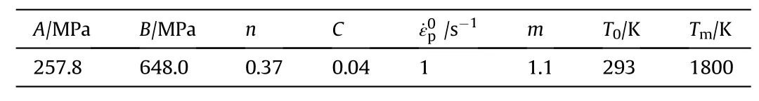
Table 1 Johnson-Cook plasticity parameters for S355-J2 from Ref. [10].
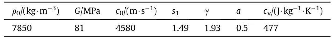
Table 2 Typical physical properties for mild steel.
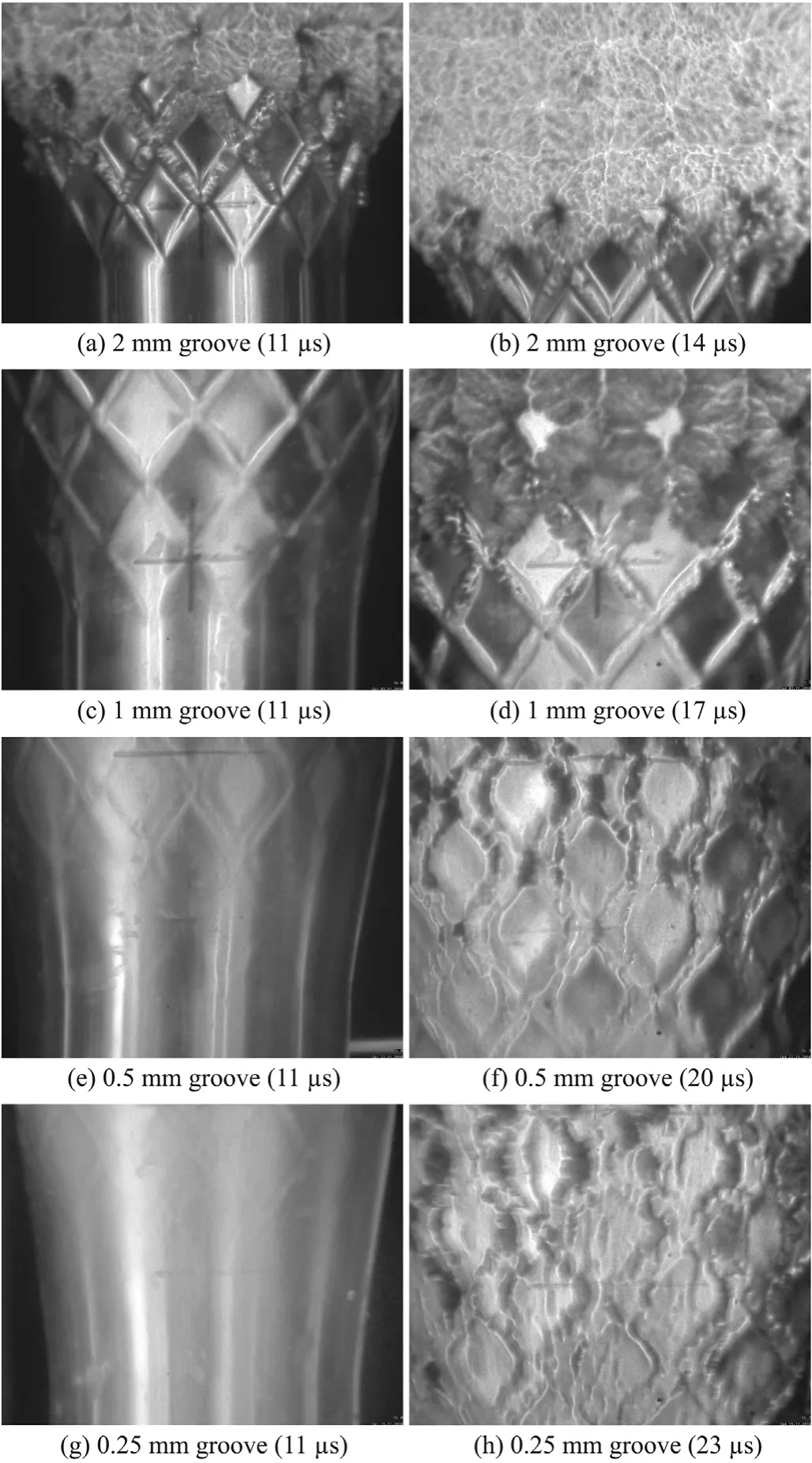
Fig. 5. HSFC-pictures at two different times after initiation showing the deformation pattern of casings with groove depths: (a,b) 2.0 mm, (c,d) 1.0 mm, (e,f) 0.5 mm and(g,h) 0.25 mm, respectively.
In the Impetus simulations, third order Lagrangian solid elements were used to discretise the casing and discrete particles were used to treat the high-explosive product gases. A quarter of the charge was modelled with symmetry planes in two orthogonal planes intersecting the charge axis.The complete model consisted of 90 000 solid elements and 10 million discrete particles.
In the LS-DYNA simulations, initial efforts to use a coupled approach with a MMALE formulation for the HE and a Lagrangian formulation for the casing were unsuccessful due to problems with leakage.Hence it was decided to use a purely MMALE formulation to describe both the HE and the casing. To be able to capture the fragmentation using a MMALE formulation it is necessary to use relatively fine mesh and to reduce the computational cost the smallest possible computational domain was used. Due to the rotational symmetry of the charge, only a small sector (a half fragment column with a 15°opening angle)needs to be included in the model. Since the MMALE formulation works best with hexagonal elements,a small core of the HE around the axis was replaced by a rigid boundary to avoid very small tetragonal elements at the charge axis.Symmetry boundary conditions were used at the sector planes. Typical element lengths were 0.25 mm and the complete model consisted of 3.5 million solid elements. The computational geometry for the two solvers are shown in Fig. 4.
Fig. 6. Flash X-ray pictures of the fragmentation process for different groove depth: (a) 2.0 mm, (b) 1.0 mm, (c) 0.5 mm and (d) 0.25 mm, respectively.

Fig.7. HSV-picture at two different positions from the charge:(a)at the position when the fragments leave the expanding fire ball(two fragments are marked with circles)and(b)at 1.2e1.5 m from the charge were the terminal velocity of the four leading fragments are evaluated(fragments from other columns are also visible in the picture behind the leading fragments). The direction of flight is to the right in the pictures.
In both the LS-DYNA and Impetus simulations a Johnson-Cook constitutive model and a Grüneisen equation of state (EOS) were used to describe the casing.The Johnson-Cook(JC)plasticity model reads
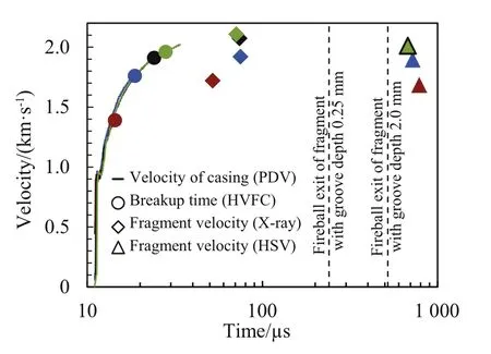
Fig. 8. Velocity of casing (PDV - solid line) and final fragments (X-ray- diamonds and HSV - triangles) versus time for four different groove depth: 2.0 mm (red), 1.0 mm(blue), 0.5 mm (black) and 0.25 mm (green). The time of breakup determined from HSFV pictures for each groove depth are indicated by filled circles and the minimum and maximum fireball exit times are indicated with vertical dashed lines.
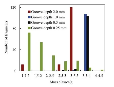
Fig. 9. Fragment mass distribution for groove depths 2.0 mm (red), 1.0 mm (blue),0.5 mm(black)and 0.25 mm(green).One fragment of each type were cut as indicated in Fig. 10 after which the surface was prepared for microstructure analysis. The cut direction corresponds to the tangential direction of the casing. .
The Grüneisen equation of state for a material with a linear shock velocity us-particle velocity uprelation us¼c0þ s1upreads
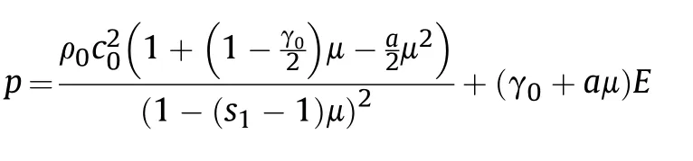
where p is the pressure,E is the internal energy per initial volume unit,is the compression and g0and a are the two Grüneisen parameters, see e.g. Ref. [8]. Parameters for the JC plasticity model for S355-J2 steel were taken from Ref. [10] and are listed in Table 1 while parameters typical for mild steel was used for density, EOS, shear modulus and specific heat capacity which are listed in Table 2.
Casing fracture was treated by an incremental damage model coupled to a fracture criterion. In LS-DYNA the JC-damage model with parameters from Ref. [10] was used together with a mass preserving erosion criterion (*ALE_FRAGMENTATION fragtyp ¼ 2).In the Impetus simulations the Cockroft-Latham (CL) damage model was used in combination with a node-splitting algorithm.The CL-model contains in its simplest form only one free material parameter Wcwhich was calibrated against uniaxial tensile tests on S355J2 performed at our laboratory. The best fit was obtained for Wc¼1.4156 GPa.
The HE was described by a JWL EOS in LS-DYNA and by a modified ideal gas with co-volume corrections in Impetus with parameters for Comp-B, both using a programmed burn model to describe the propagation of the detonation.The parameters for the JWL EOS in LS-DYNA were taken from Ref.[11]and from the built in library in Impetus(version 4.0.2157).The Impetus HE EOS contains four input parameters; initial density, initial energy per unit volume, polytropic gamma and co-volume at initial density. The two first parameters are the same as in the JWL EOS and the values 1.45 and 0.264 were used for the gamma and the co-volume,respectively.
3. Results
3.1. Fragmentation and acceleration of the casing
High speed framing camera pictures of the deformation and breakup of the casing are shown in Fig. 5. The field of view is centred in-between fragment 2A and 3A, see Fig. 3. The selected pictures of the charge are taken at two different times after initiation,the first when the detonation wave has passed the centre of view and the second when the casing starts to break up. The pictures show that the deformation of the casing gradually changes from local push-out of material close to the deep grooves to a more global deformation of the whole casing with a tendency of necking for shallow grooves. Fig. 6 show X-ray pictures taken after the breakup of the casing. The pictures are used to determine the velocity,rotation and breakup of the fragments in column 1Ae4A,see Fig. 3. Examples of high speed video pictures showing fragments leaving the fireball and traveling in free air approximatively 1.4 m away from the initial charge position is shown in Fig. 7.

Fig.10. Fragments used for examination of microstructure and deformation pattern. The cut direction is indicated by the dashed line. The Groove depths seen from the left: (a)2.0 mm, (b) 1.0 mm, (c) 0.5 mm and (d) 0.25 mm, respectively.
The evaluated data from the PDV, HSFC, X-rays and HSV versus time (logarithmic) after initiation of the four different charges are given in Fig. 8. The data correspond to the fragment 3A and 3B in Fig.3.The data show that,after breakup,the fragments continues to accelerate. The velocity from the X-ray pictures is slightly higher than the one from the HSV-pictures indicating a high aerodynamic drag as soon as the fragments exits the fire ball.
3.2. Fragment mass distribution and fracture surface analysis
The fragments from the sawdust pit test were collected for fragment mass distribution determination and fracture surface analysis.Typically,about 97%of the casing mass was recovered.The resulting fragment mass distribution divided in mass classes of 0.5 g is shown in Fig. 9.
Fig.11 shows typical fracture surfaces of the fragments in Fig.10.The inside of the casing is at the top of the pictures and the depth of the grooves is marked with an arrow.The shape and orientation of the fracture surfaces indicate a shear failure except in the case of the deepest groove,2.0 mm,where the fracture is more similar to a tensile fracture.In this case,a number of dimples can be observed in the lower end of picture (a) in Fig.11.
Fig.12 shows images of the microstructures from the fragments in Fig. 10. The initial microstructure is shown in Fig. 12 (a). The colours represents crystal grain orientation where blue corresponds to the crystallographic axis [111], i.e., the diagonal of the BCC structure in Ferrite.
The initial grain size is around 8e9 mm. The microstructure shows a tendency of orientation in parallel with the tangential direction of the casing.This is probably because the casing material is manufactured through a rolling process.
The amount of expansion of the casing before fragmentation is clearly seen as a tangential stretching of the microstructure. The degree of stretching depends on the depth of grooves, see Fig.12.The grain size decreases also, probably due to the formation of deformation twins. These are formed due to the initial shock loading and seems to work as grain boundaries under the following deformation process.
3.3. Numerical simulations
The casing deformations at the experimentally determined breakup time is shown in Fig.13 and should be compared with the high-speed photos in Fig. 5. Both software are able to predict the change in deformation behaviour when the groove depth is decreased from 1.0 mm to 0.5 mm.The approximate time for onset of fragmentation is also in agreement with the experiments.It can be observed,especially clear in the Impetus simulations,that small fragments from the deep groves are ejected at a higher velocity than the main fragments. This phenomenon is also seen in the radiographs in Fig. 6.
Fig.14 shows the acceleration of a node located in the middle of fragment 3A for the charge casing with 0.5 mm groves as predicted by LS-DYNA. The complete acceleration history is in agreement with the experimental results compiled from the different diagnostic tools and shows that,for this groove depth,that LS-DYNA can both predict the acceleration before fragmentation(essentially the PDV-trace) and also the post-acceleration after the casing has started to breakup and high explosive gases are escaping through the cracks. A compilation of all predicted terminal velocities for fragment 1e4 in column A is presented in Fig. 15 together with corresponding experimental values evaluated from the radiographs.It can be noted that Impetus consistently over-predicts the terminal velocities while LS-DYNA is in agreement with the experiments except for the casing with the deepest groves (2.0 mm)where the predicted velocity is slightly too high.
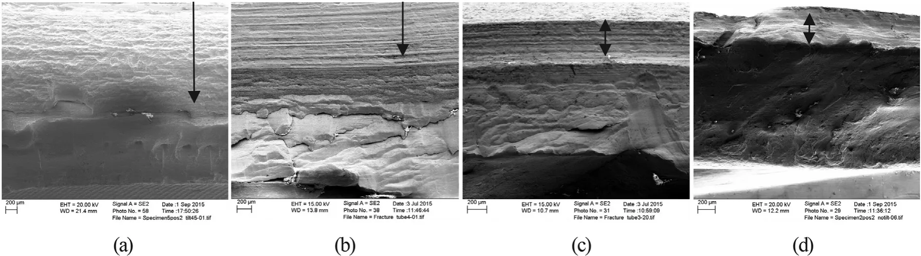
Fig.11. Fracture surfaces of the different casing types. Groove depths from the left: (a) 2.0 mm, (b) 1.0 mm, (c) 0.5 mm and (d) 0.25 mm.

Fig.12. Microstructure of undeformed case material (a) and fragments: (b) 2.0 mm, (c) 1.0 mm, (d) 0.5 mm, (e) 0.25 mm. The images are oriented so that the casing thickness is directed upwards and the tangential direction is directed horizontal in the pictures.
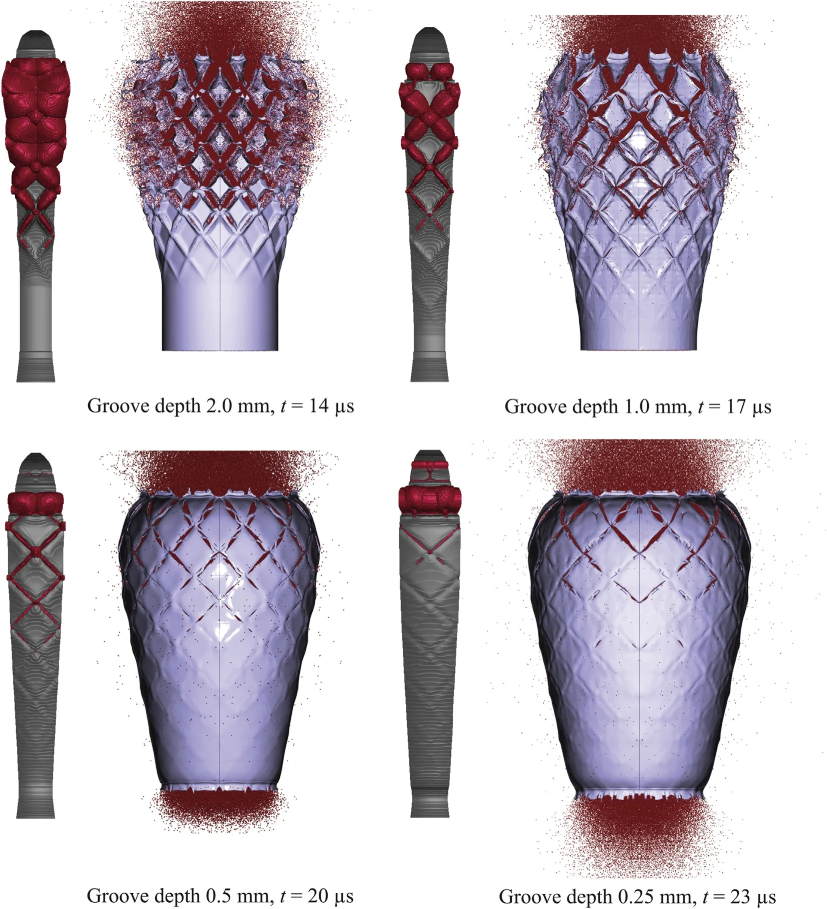
Fig.13. Casing deformation as predicted by LS-DYNA (left) and Impetus (right) for different groove depths at experimentally determined break-up times. The computational time for one complete simulation was 25e30 h with Impetus on a standard workstation using GPU-acceleration and 20 h on four CPU-cores with LS-DYNA.
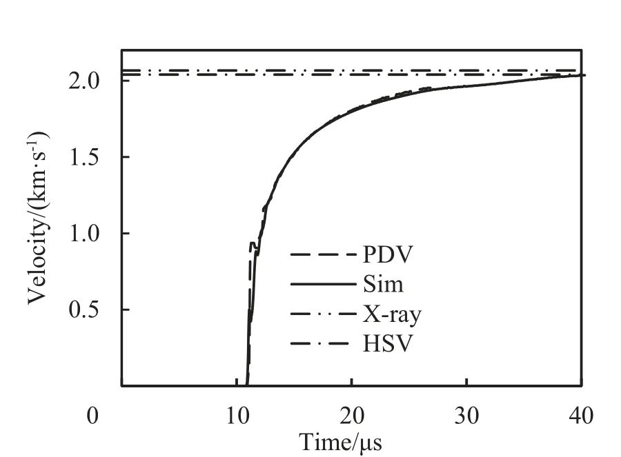
Fig.14. Acceleration of fragment number 3A for a charge with a 0.5 mm groove depth.Solid line shows the LS-DYNA result and dashed line shows the PDV-signal. Dasheddotted lines indicates the terminal fragment velocity from X-rays(upper line)and from HSV-pictures (lower line), respectively.
4. Discussion and conclusions
Numerical simulations pose an opportunity to design and evaluate the performance of fragmentation charges in an effective manner. However, in order to give reliable predictions, it is necessary that it can handle the different physical processes that occurs in a fragmenting charge.These includes the initial deformation and break-up of the casing,the leakage of the high-explosive gases and their influence on the terminal velocity of the fragments. Thus, an accurate plasticity law incorporating strain rate effects is necessary to describe both the global and the local deformation before fracture.A fracture law describing the fracture strain as function of the stress state is needed to predict the dominant fracture mode, e.g.tensile or shear induced fracture,and to predict the break-up time.A detailed modelling of the high-explosive gases and their interaction with the casing is also necessary in order to predict postfracture acceleration of the fragments. In this study, the two finite element software, LS-DYNA and Impetus, has been compared to detailed experiments to test their ability to predict the deformation,fragmentation and acceleration of a controlled fragmentation charge casing.
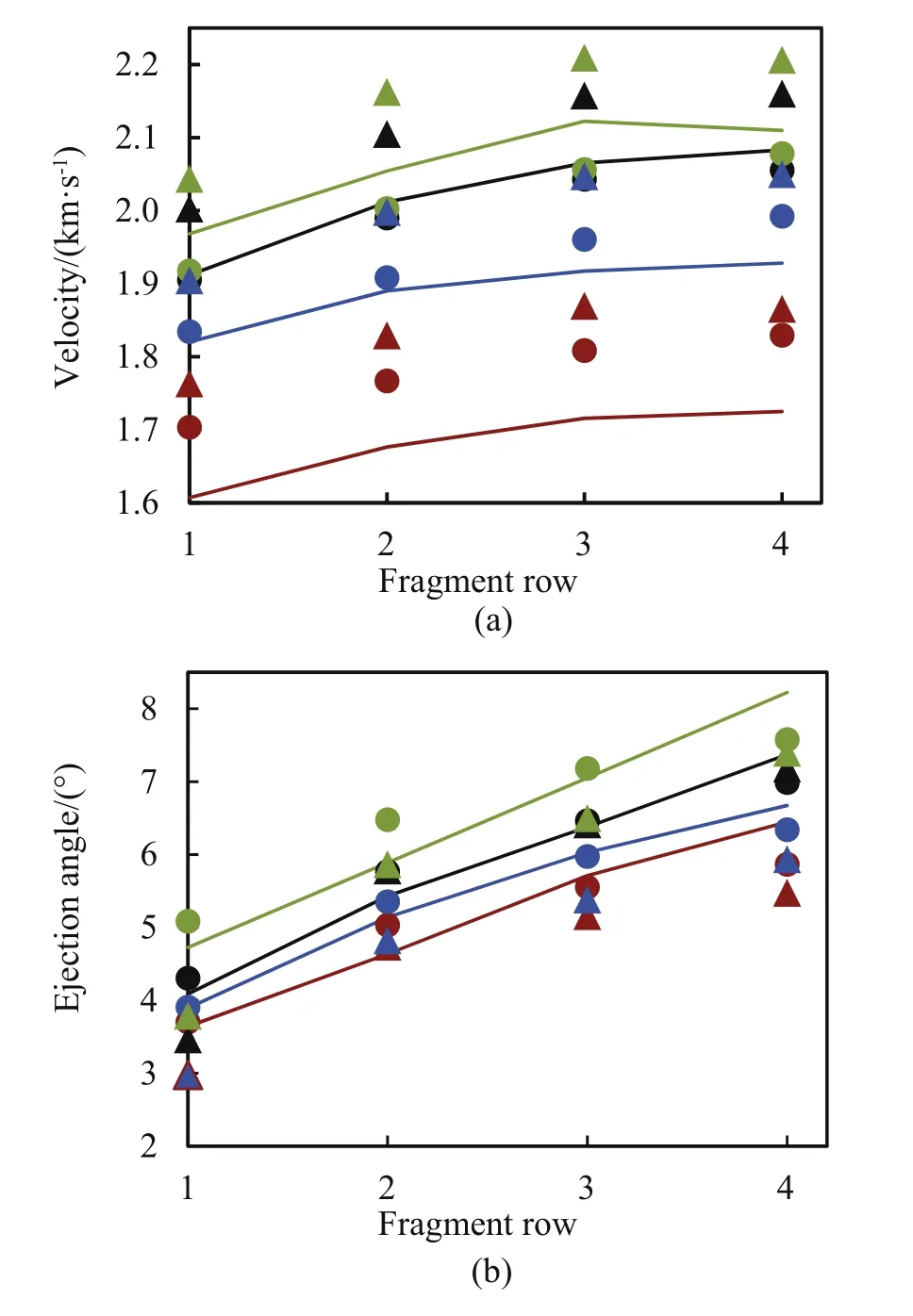
Fig.15. Comparison between experimental and simulated terminal velocities (a) and fragment ejection angles (b) for fragment 1Ae4A for the four different groove depths 2.0 mm (red), 1.0 mm (blue), 0.5 mm (black) and 0.25 mm (green). Solid lines are experimental values evaluated from the radiographs, filled circles represents the LSDYNA simulations and filled triangles, the Impetus simulations, respectively.
The deformation of the casing depends strongly on the groove depth as shown in Fig. 5. For deep grooves, the case material is rapidly punched out from the bottom of the grooves.This material forms a fast expanding cloud of small fragments ahead of the main fragments,as seen in Fig.6(a)and Fig.6(b).The fracture mode is in this case dominantly tensile as seen in the SEM-picture,Fig.11(a).For shallow grooves, the deformation is less localized with a tendency of necking in the region of the groove. This is most pronounced for groove depth 0.5 mm, see Fig. 5(e) and Fig. 5 (f). The fracture mode is in this case mainly shear controlled.This change in deformation mode was captured by the numerical simulations, as seen in Fig.13. The predicted mode of deformation is sensitive to the strain rate effects. A too high strain rate dependency will suppress necking and do not reproduce the observed deformation behaviour. The relatively low resolution of the computational grid and the simplicity of the fracture models used did not allow for a detailed modelling of the fracture process.Nevertheless,the global fracturing of the casing was in accordance with the experiments,see Figs.5 and 13,although the casing is fracturing slightly later in the simulations than in the experiments for the 0.25 mm groves.
The post breakup velocity increase are largest for the casing with the 2.0 mm grooves,a nearly 20%increase was observed after the breakup of the casing.The post breakup acceleration decreases rapidly for shallower grooves, and the velocity increase is only around 8%or less for 0.5 mm and 0.25 mm deep grooves,see Fig.8.On the other hand, the premature fracturing of the casing with deep grooves result in markedly reduced terminal velocity of the fragments.The velocity of fragment 4A decreases from 2080 m/s for 0.5 mm grooves to 1720 m/s for 2.0 mm grooves. Decreasing the depth of grooves even further will only increase the velocity slightly but leads to heavily deformed and in most cases ruptured fragments. The simulated acceleration histories are in agreement with the experimental results compiled from the different diagnostic tools and shows that LS-DYNA can both predict the acceleration before fragmentation (essentially the PDV-trace) and also the post-acceleration after the casing has started to breakup and high explosive gases are escaping through the cracks, as seen in Fig. 14. Impetus on the other hand consistently over-predicts the terminal velocities,as seen in Fig.15.A possible explanation is that the high explosive parameters in Impetus were not fully optimized.The code uses an Ideal Gas with co-volume. According to Impetus Afea, the constant gamma was chosen to match its value at high expansions where thermal effects are dominating and the remaining parameter, related to the co-volume effect, was chosen to match the isentrop from the CJ-state as close as possible. The main problem with this model is that it has few parameters.A good match at both high and low pressures is wherefore not always possible.Later versions of the Impetus material library uses another set of parameters which results in much lower velocities than those seen here. An optimized parameter set for metal accelerating applications may give better agreement.
The influence of groove depth on the fragment mass distribution is shown in Fig.9.For the shallowest groove depth,0.25 mm,most of the recovered diamond shaped fragments were split in smaller pieces.The small number of intact fragments all had multiple axial cracks,see Fig.10(d).The severe deformation and fracturing of the 0.25 mm groove fragments are reproduced in the Impetus but not in the LS-DYNA simulations.The fragmentation process in this type of shallow grooved casing seems to be a mix of controlled and natural fragmentation where spatial variations in material properties are of importance.To simulate this mixed mode behaviour it is necessary to include some randomness in the simulation model.The discrete particles describing the HE in the Impetus model may act as such random seed while the ALE model used in LS-DYNA lacks such imperfections.
The study shows that detailed numerical simulations using relevant material models and calibrated material parameters can predict both the fragment shape and the velocity of a controlled fragmenting charge with high fidelity. Fast running models often lacks the ability to resolve the influence of grooves on the terminal velocity of the fragments and the fragment distribution. The presented experimental data can be used for benchmarking numerical simulation tools and for developing simplified acceleration models for fast running semi-analytical lethality software.
Acknowledgment
This work was performed under a science and technology program on long range weapon effects. The program is funded by the Swedish Armed Forces under Grant No AF.9220616.
- Defence Technology的其它文章
- 31st International Symposium on Ballistics, Hyderabad, India, 4e8 November 2019
- Analysis of global momentum transfer due to buried mine detonation
- Modeling of the whole process of shock wave overpressure of freefield air explosion
- Experimental studies of explosion energy output with different igniter mass
- Investigation on the influence of the initial RDX crystal size on the performance of shaped charge warheads
- Bore-center annular shaped charges with different liner materials penetrating into steel targets