
Thermal-structure coupling analysis and multiobjective optimization of motor rotor in MSPMSM
2019-08-13 02:22:12LuxinZHAIJinjiSUNXinMAWeitoHANXiosnLUO
CHINESE JOURNAL OF AERONAUTICS 2019年7期
Luxin ZHAI ,Jinji SUN ,Xin MA ,*,Weito HAN ,Xiosn LUO
a School of Instrumentation Science&Opto-electronics Engineering,Beihang University,Beijing 100083,China
b CRRC Qingdao Sifang Co.,Ltd.,Qingdao 266111,China
KEYWORDS FEM;MSPMSM;Multi-objective optimization;Thermal stress;Thermal-structure coupling analysis
Abstract With the high speed,the rotor of magnetically suspended permanent magnet synchronous motor(MSPMSM)suffers great thermal stress and mechanical stress resulting from the temperature rise problem caused by rotor losses,which leads to instability and inefficiency.In this paper,the mechanical-temperature field coupling analysis is conducted to analyze the relationship between the temperature field and structure,and multi-objective optimization of a rotor is performed to improve the design reliability and efficiency.Firstly,the temperature field is calculated by the 2D finite element model of MSPMSM and the method of applying the 2D temperature result to the 3D finite element model of the motor rotor equivalently is proposed.Then the thermal-structure coupling analysis is processed through mathematic method and finite element method(FEM),in which the 3D finite element model is established precisely in a way and approaches the practical operation state further.Moreover,the impact produced by the temperature and structure on the mechanical strength is analyzed in detail.Finally,the optimization mathematical model of the motor rotor is established with Sequential Quadratic Programming-NLPQL selected in the optimization scheme.Through optimization,the strength of the components in the motor rotor increases obviously and satisfies the design requirement,which to a great extend enhances the service life of the MSPMSM rotor.
1.Introduction
Magnetic bearings with many advantages,such as no wearing,micro vibration,and high precision,have been widely applied in the field of aeronautics such as flywheel1in satellite,control momentum gyro2,3for large space station,inertially stabilized platform4for aircraft,and so on.The magnetically suspended PMSM(MSPMSM)supported by magnetic bearings solves the mechanical friction and possesses a long life with high speed and low loss,which is adapted for aeronautical application, especially for aero-engine.5-7However, the rotor of MSPMSM will bear huge mechanical stress generated by the centrifugal force,weakening the strength of the motor rotor in a high-speed operation,especially the permanent magnet.Therefore,mechanical stress analysis and optimization of the permanent magnet for the MSPMSM rotor are essential to ensure that it is strong enough to withstand the centrifugal force.In Refs.8-10,mechanical stress is analyzed by finite element method (FEM) to achieve the sufficient mechanical strength.Even novel configuration of the motor rotor or design strategy is proposed to satisfy the various performance requirements as well as the mechanical strength regarded as a significant constraint regularly in the optimal design process.11-13
In addition,the temperature rise is also a distinct problem troubling the rotor of MSPMSM.Due to the high speed,it is difficult for the much heat produced by the rotor to release in time,which results in the high temperature of the rotor.The high temperature field can generate the great thermal stress that has a pronounced effect on the strength of the motor rotor.For this reason,many researchers studied the thermal behavior of high-speed PMSM.
In Refs.14-16the temperature field of PM motor is analyzed by several methods,such as lumped thermal scheme,2D/3D numerical model, thermal-network and FEM, which are validated and compared with each other.In Ref.17the electromagnetic performance and loss distribution are determined by FEM and the electro-thermal coupling analysis is also carried out to study the thermal performance of high-speed PM motor.In Ref.18an effective method is proposed to analyze the centrifugal force and heat transfer at the same time,making it possible to predict mechanical and thermal stability in the primary design stage.
For the MSPMSM supported by magnetic bearings,the temperature rise problem of the rotor is more serious because of its complete suspension.With the high speed,the motor rotor suffers great thermal stress and mechanical stress concurrently.Therefore,it is necessary to calculate the temperature field of the MSPMSM in the operation state and understand its impact on the strength of the motor rotor.In this paper,we propose the thermal-structure coupling analysis on the motor rotor and the multi-objective optimization through the approach of combining FEM and Sequential Quadratic Programming19-21to analyze the mechanical properties accurately and ensure the strength safety.
2.Structure of MSPMSM
The configuration of the MSPMSM is shown in Fig.1,which mainly consists of radial magnetic bearings,axial magnetic bearing, motor stator, motor rotor, shaft and enclosures.The radial magnetic bearings(RMB)and axial magnetic bearing(AMB)are used to realize suspension of the shaft so that the MSPMSM can operate stably at high speed without mechanical friction.There are some water cooling passages between the outer and inner enclosures,which locate in the position of the motor stator with high power loss to decrease its temperature effectively.To reduce the stress of permanent magnet at high speed,as designed in Fig.2,it is composed of wearing sleeve,shroud sleeve and permanent magnet.The wearing sleeve is made of GH4169 with perfect mechanical properties,and the shroud sleeve is made of copper,which envelops the permanent magnet.An interference fit is applied on the fitting surfaces of the wearing sleeve and shroud sleeve,which can deform the shroud sleeve largely and press the permanent magnet on the shaft to make the permanent magnet in the state of compressive stress as soon as possible.Because the compressive strength of the permanent magnet is much larger than the tensile strength,the state of compressive stress will increase the strength safety factor and operational life.
3.Loss analysis and temperature FEM analysis
Temperature FEM analysis is the basis for the thermalstructure coupling analysis to calculate the temperature field accurately.And the premise of thermal is temperature,which is caused by the losses.So,we first analyze the losses of MSPMSM including copper loss,iron loss and windage loss,and then FEM is applied to carry out the thermal analysis of the MSPMSM in the thermal steady state because of its high precision and computing efficiency.In addition,the temperature result calculated from the 2D finite element model can be used to the 3D finite element model mechanical analysis.
3.1.Loss analysis
MSPMSM,as an electromechanical energy conversion mechanism,inevitably generates losses during the process of electromechanical energy conversion. These losses eventually become mostly heat,causing the temperature of various parts of the MSPMSM to rise.The total losses P are mainly composed of three parts:
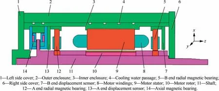
Fig.1 Configuration of MSPMSM.
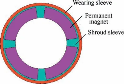
Fig.2 Motor rotor.

where Pcopper,Pironand Pwindageare the copper loss,iron loss and windage loss respectively.
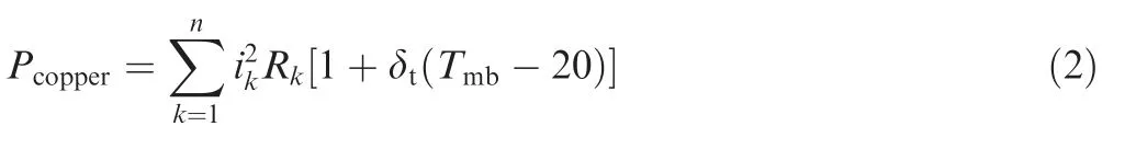
The current flowing through motor windings or magnetic bearing coils can provide the needed force as well as cause copper loss,which can be calculated by
The magnetic field in the stator core changes with time and space. This changing magnetic field generates iron losses,including hysteresis loss,eddy-current loss and excess loss in the core,which can be obtained by
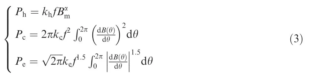
where Phis hysteresis loss,Pcis eddy-current loss,Peis excess loss,kh,α,kcand keare loss coefficients which can be obtained by fitting the loss curve tested at a given frequency,and Bm,f and B(θ)are magnetic flux density amplitude,re-magnetization frequency and magnetic flux density waveform of ferromagnetic material respectively.
For motor,frequency f is equal to the product of motor frequency and number of pole pairs,and Bmand B(θ)are the magnetic flux density amplitude and magnetic flux density waveform of ferromagnetic material of motor respectively.So,the iron loss of motor Pm_iron-losscan be obtained by

For radial magnetic bearings with a magnetic polarity sequence of NSSNNSSN,frequency f is equal to four times the rotation frequency,Bmand B(θ)are the magnetic flux density amplitude and magnetic flux density waveform of ferromagnetic material of radial magnetic bearings respectively.So,the iron loss of radial magnetic bearings PRMB_iron-losscan be obtained by

For axial magnetic bearings,iron loss is negligible due to small magnetic field fluctuations.
It can be seen from the MSPMSM structure in Fig.1,due to the high surface speed and no contact between rotor assembly and stationary parts,windage losses mainly occupy on the cylindrical rotor surface and two sides of the disk-shaped structure(thrust-disc)of the axial magnetic bearing rotor,which can be categorized as follows:
where Pcyl_windage-lossis the windage loss of cylindrical rotor surface,Pthr_windage-lossis windage loss of thrust-disc,Cfis friction coefficients of the cylindrical surface,ρais the air density,ω is the rotor angular velocity,rris the radius of rotor,l is the axial length of the rotor cylindrical surface,μ is the dynamic viscosity of the air,and R1and R2are outer radius and inner radius of axial magnetic bearing thrust disc respectively.
The equivalent thermal network method is used to calculate temperature rise problems by thermal network established according to the heat transfer direction and path of the motor.This method concentrates the loss heat source on each discrete node which is connected by thermal resistance.There are basically three basic modes of heat transfer:heat conduction,convection and radiation.
Heat conduction can be calculated by
where L,λcand Aheat_conductionare the length of heat conduction path,the thermal conductivity of the object and the crosssectional area of heat conduction respectively.
Convection can be calculated by
where αcand Aconvectionare the heat transfer coefficient of convection and the contact surface area of convective object respectively.
Radiation can be calculated by
where G is thermal conduction between two parts of the conduction heat,and ΔT is the temperature difference between the two parts of the conduction heat.
Finally,thermal analysis of the entire motor is performed through the thermal network model and the losses of MSPMSM composition can be calculated as Table 1 shows.
3.2.2D FEM temperature of MSPMSM
Considering computing efficiency and enough precision,2D finite element model of the MSPMSM is built by ANSYS,as shown in Fig.3.The MSPMSM operates in the conventionalenvironment generally, so the heat transfer way mainly includes conduction,convection and radiation,where heat conduction and radiation can be simulated through the thermal conductivity and emissivity of the materials,as shown in Table 2.As to convection,its coefficients can be calculated by the formulas proposed in Refs.22,23
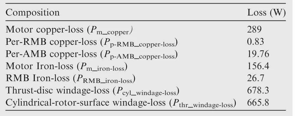
Table 1 Results of loss analysis.
As a boundary,the heat generation rate is related to the power losses of certain components,such as motor stator,motor rotor,motor windings,radial magnetic bearing,axial magnetic bearing and so on.The power losses involve copper loss,iron loss and windage loss,which can be determined with the power losses separation based on the power consumption test experiment and experience formulas.24-30Because the contact thermal resistance caused by the clearance fits between the contact components can hinder conduction,it is dealt with through the contact elements in the finite element model,of which the target surface and contact surface apply the elements TARGE169 and CONTA172 respectively.The thermal contact conductance serving as the contact thermal resistance in the contacts can be expressed as

where Acomponentdenotes the contact area of components;λ1and λ2denote the thermal conductivities of the contact components;δ denotes the length of the clearance between the contact components.
3.3.Temperature simulation
The temperature distribution of the MSPMSM and the motor rotor are shown in Figs.4 and 5 in the thermal steady state with the 25°C circumstances.The temperature of the enclosures,the stator of radial magnetic bearing and the stator of axial magnetic bearing are lower and about 27.6-43°C,whereas that of the motor stator and the motor windings are a bit higher and the maximum value is about 82.4°C.The main reasons are as follows:(1)the motor stator and motorwindings with the high-power losses will generate much heat that results in their higher temperature.(2)The cooling water flowing between the enclosures can absorb the heart by convection in time,keeping the enclosures at lower temperature.
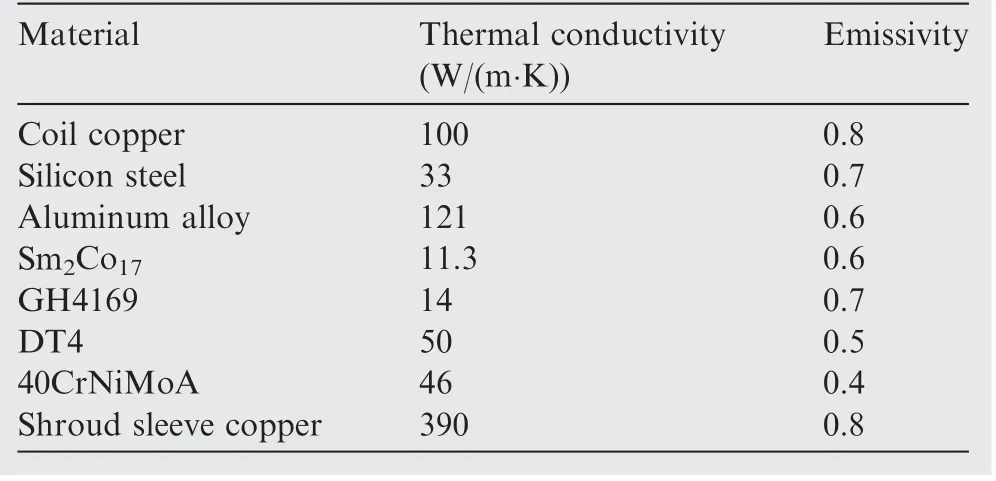
Table 2 Conductivity and emissivity of materials.
As Figs.4 and 5 show,the maximum temperature 98.2°C appears in the motor rotor.When the MSPMSM operates in high speed,the rotor assembly will rub with air,causing the windage loss.Moreover,the shroud sleeve will produce the large eddy current loss due to the alternating magnetic field.However,the heat transfer ways of the rotor assembly in the suspension state only include convection and radiation,where the radiation efficiency itself is lower and convective heat exchange also becomes less with the air surrounding the rotor assembly reaching a high steady temperature.Therefore,the high heat production and the low heat dissipation lead to the maximum temperature of the motor rotor.
3.4.3D FEM temperature field of motor rotor
To analyze the mechanical properties of the motor rotor accurately and effectively,a quarter 3D finite element model is built necessarily in Fig.6.As mentioned previously,the temperature of the rotor shown in Fig.5 should be considered and applied to the 3D finite model as a load equivalently.Fig.5 indicates that the temperature of the components is gradually variable with the axial distance.So,the relationship between the temperature and the axial distance can be obtained by the path operation in ANSYS,as shown in Fig.7.And then,we perform 4th degree polynomial fit to the curves and acquire the T-y functions.Finally,we load the T-y functions on the corresponding surface of the components in the 3D finite element model and do solution.The result calculated by 3D finite element model is shown in Fig.8.
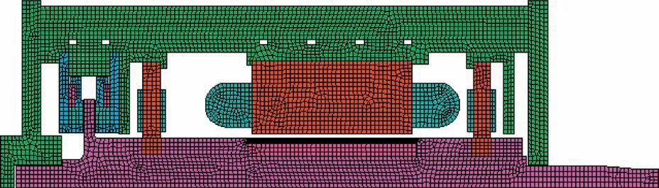
Fig.3 2D finite element model of MSPMSM.
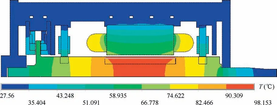
Fig.4 Temperature distribution of MSPMSM.
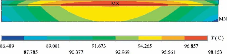
Fig.5 Temperature distribution of motor rotor in 2D FEM.
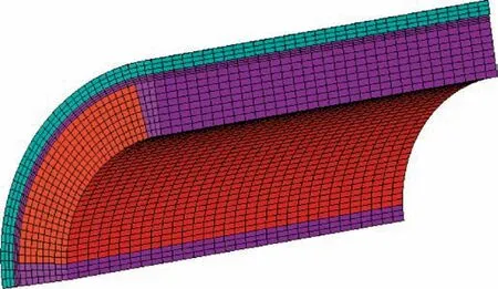
Fig.6 A quarter 3D finite element model of motor rotor.
Fig.8 demonstrates that the temperature distribution of 3D finite element model has good agreement with that of 2D one shown in Fig.5.The method of applying the temperature result of 2D finite model to the 3D one equivalently is validated,making it more convenient and efficient to analyze the mechanical properties of the motor rotor in the following.
4.Thermal-structure coupling analysis of motor rotor
According to the linear thermal stress theory,the stress resultant is the algebra superposition of the stress caused by the strain and the stress proportional to the temperature variation.For the MSPMSM rotor in the operating state,the stress in its components is the comprehensive result of the mechanical stress and thermal stress.In the following,the stress is analyzed by the mathematical method and FEM respectively.
4.1.Mathematic model of stress
To establish the mathematical model of the stress, some assumptions are made as follows:(1)all the components are treated as plain annulus equivalently.(2)The pressure loaded on the fitting surface is uniform.(3)The end effects in the axial direction are neglected.Due to the axial symmetry of the MSPMSM rotor,the displacement and stress are axisymmetric in the polar coordinate system.According to the Lame equations,the radial displacement of the wearing sleeve in the static state can be calculated by
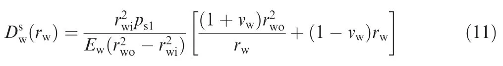
where rwois the outer radius of the wearing sleeve;rwiis the inner radius of the wearing sleeve;Ewis the Elasticity Modulus of the wearing sleeve;νwis the Poisson's ration of the wearing sleeve;ps1is the pressure between the wearing sleeve and the shroud sleeve;rwis the arbitrary radius of the wearing sleeve and rwi≤rw≤rwo.
The radial displacement of the shroud sleeve in the static state can be calculated by
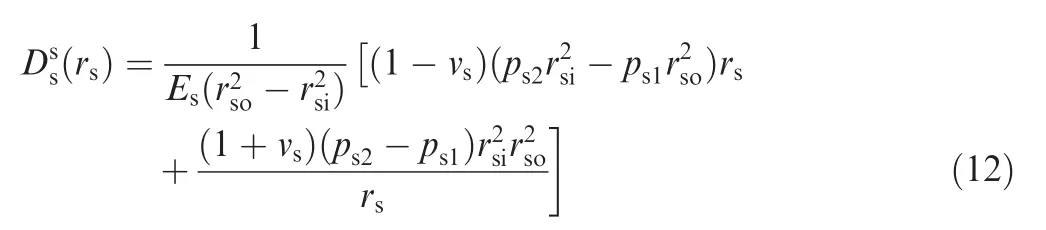
where rsois the outer radius of the shroud sleeve;rsiis the inner radius of the shroud sleeve;Esis the Elasticity Modulus of the shroud sleeve;νsis the Poisson's ration of the shroud sleeve;ps2is the pressure between the shroud sleeve and the permanent magnet;rsis the arbitrary radius of the shroud sleeve and rsi≤rs≤rso.
Similar to the shroud sleeve,the radial displacement of the permanent magnet in the static state can be calculated by

where rmois the outer radius of the permanent magnet;rmiis the inner radius of the permanent magnet;Emis the Elasticity Modulus of the permanent magnet;νmis the Poisson's ration of the permanent magnet;rmis the arbitrary radius of the permanent magnet and rmi≤rm≤rmo.

Fig.7 Temperature variation with axial distance.
The interference δs1between the wearing sleeve and shroud sleeve and the initial clearance λsbetween cylindrical surfaces of the shroud sleeve and permanent magnet can be expressed as
Substitute Eq.(11),Eq.(12)and Eq.(13)into Eq.(14),and the pressures ps1and ps2can be obtained.
With the pressure ps1and ps2calculated,the mechanical stresses of the components in the static state are given in Table 3.
In the dynamic state,the mechanical stresses of the components generated by the centrifugal force can be calculated by
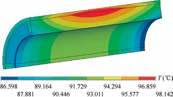
Fig.8 Temperature distribution of motor rotor in 3D finite element model.
In the thermal steady state,the thermal stresses of the components are generated by
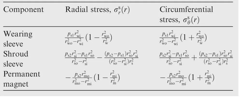
Table 3 Static stresses of components.
Then,the resultant stress of the component in the operation state can be expressed as

The Von Mises stress is given by

4.2.Thermal-structure coupling analysis by FEM
The stress distribution of the 3D model is far more complicated than the plane stress distribution expressed in the mathematical model, if the temperature, centrifugal force and interference fit are taken into consideration simultaneously.Therefore,FEM is chosen to analyze the comprehensive result generated by various types of loads.The structure dimensions of the MSPMSM rotor are shown in Fig.9 and Table 4.
The mechanical parameters of the corresponding material are shown in Table 5.
The 3D finite element model shown in Fig.10 is established in accordance with the assembling process and operation state to make it closer to the practical condition.The interference fit between the wearing sleeve and shroud sleeve is equivalent to the bonded type contact 1,in which the interference can be adjusted.The initial clearances between the shroud sleeve and the permanent magnet are equivalent to the rough type contact 2,3,4,which can avoid the relative sliding between the fit surfaces.After all,the pressures between the components prevent them from sliding with each other.The shaft model is built to serve as auxiliary model,which can restrain the displacement boundary of the permanent magnet exactly together with the rough type contact 5.The shroud sleeve is fixed on the shaft through the bolts, so the connections between them recommend bonded types.In the conventional analysis,the auxiliary model of shaft is always ignored to simplify the finite element model and save calculation time.Because of this,the inner diameter displacement boundary of the permanent magnet has to be restrained to eliminate the under-constrained problem in the solving process.However,the inner diameter of the permanent magnet will generate displacement based on the mathematical model with the action of the centrifugal force.Therefore,the compulsive displacement constraint is unreasonable,which increases the stress in the inner diameter of the permanent magnet and reduces the pressures among the permanent magnet,shroud sleeve and wearing sleeve.However,the auxiliary model of shaft and the contact 5 can deal with this problem well in Fig.10.

Fig.9 Schematic diagram of dimensions of motor rotor.
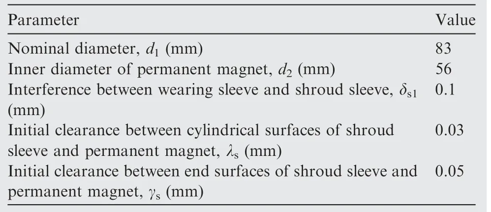
Table 4 Dimensions of MSPMSM rotor.
Through restricting the symmetry border by displacement and applying the various types of loads including interference fit,rated speed(32,000 r/min)and temperatures in Fig.8 such as the temperature of the wearing sleeve,the temperature of the shroud sleeve,the temperature of the permanent magnet and the temperature of the shaft,the stress distribution of the components is calculated without and with the temperature field respectively and the results are shown in Figs.11 and 12.
In the process of mechanical analysis and strength check,Von Mises stress is always chosen for the analysis of the plastic materials and first principle stress for the fragile materials.The permanent magnet with the fragile materials Sm2Co17possesses a better compressive strength and a poor tensile strength,so the first principle stress is applied,while the materials of the wearing sleeve and shroud sleeve own a high ductility,so it is appropriate to choose Von Mises stress.
The contrast results,as shown in Figs.11 and 12,indicate that the temperature has a certain effect on the stress distribution of the components.As Fig.8 shows,the rotor assembly has a higher temperature and the maximum temperature appears in the middle section of the wearing sleeve,shroud sleeve and permanent magnet.For the wearing sleeve,the maximum Von Mises stress without temperature is 781 MPa,and the one with temperature is 818 MPa, increasing by 37 MPa.It illustrates that the temperature field does damage to the mechanical strength of the wearing sleeve.For the shroud sleeve, Von Mises stress without temperature is 312 MPa,and the one with temperature is 261 MPa,decreasing by 51 MPa,which demonstrates that the temperature is not always disadvantageous to the mechanical strength;sometimes it may decrease the stress and increase the strength safety factor.
In Fig.11(c)and Fig.12(c),the positive stress represents pressure stress and the negative stress represents tensile stress.For the permanent magnet,the maximum first principle stress without temperature is tensile stress and the value is 59.5 MPa,while the one with temperature is also tensile stress and the value is 73 MPa,increasing by 13.5 MPa.Initially,the clearance fit is applied between the shroud sleeve and permanent magnet,which makes it convenient for the permanent magnet to slide into the shroud sleeve in the assembly process.When the MSPMSM rotor is installed on the shaft,the interference fit between the wearing sleeve and shroud sleeve deforms the shroud sleeve largely and presses the permanent magnet on the shaft.At this moment,the permanent magnet mainly suffers the pressure stress and only lower tensile stress exists in some specific positions shown in Fig.13.However,when the MSPMSM operates,the pressure stress is replaced by the tensile stress that becomes dominative gradually under the effect of the temperature and centrifugal force with the increase of speed.
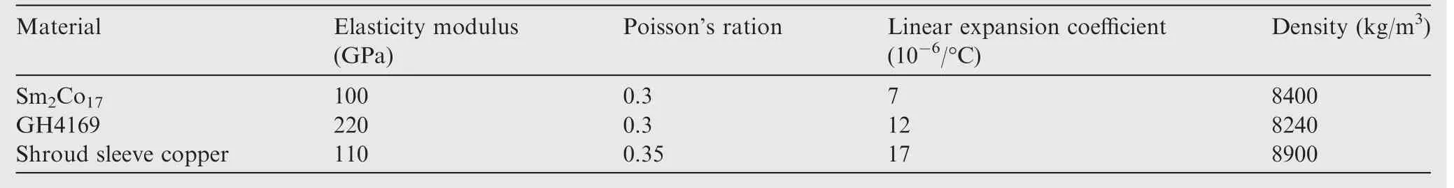
Table 5 Mechanical parameters of materials.
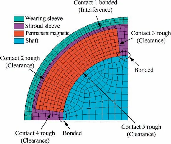
Fig.10 Accurate 3D finite element model of motor rotor for thermal-structure coupling analysis.
Through the mechanical analysis,it can be concluded that the temperature can increase the stresses of the wearing sleeve and permanent magnet,and simultaneously decrease that of the shroud sleeve.When the MSPMSM starts to operate,it will undergo the cold state first and reach the thermal steady state after a period time.So,the strength of the wearing sleeve and permanent magnet should be checked in the thermal steady state and shroud sleeve in the cold state.The strength safety factors of the components are shown in Table 6.
4.3.Relationship between interference and maximum stress of components
Based on Eq.(5)and Table 3,the stress of the components is closely related to the interference δs1.To understand its effect on the strength,we fix the initial clearances with λs=0.03 mm and γs=0.05 mm,and analyze the relationship between the maximum stress and δs1,as shown in Fig.14.
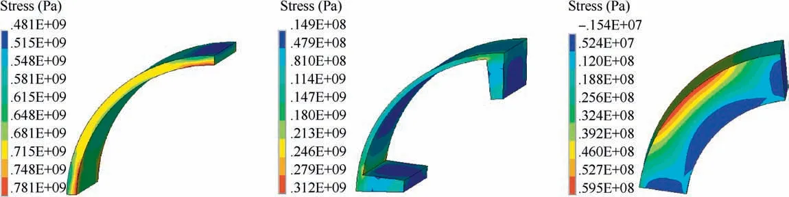
Fig.11 Stress distribution of components without temperature.
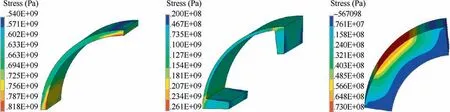
Fig.12 Stress distribution of components with temperature.
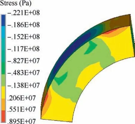
Fig.13 First principle stress of permanent magnet in static state.
As Fig.14 shows,with δs1increasing,the maximum stresses of the permanent magnet and shroud sleeve decrease substantially,while that of the wearing sleeve becomes larger gradually. It means that the larger interference benefits the strength of the permanent magnet and shroud sleeve and their strength safety factors can be improved by increasing δs1.However,the wearing sleeve should be taken into consideration at the same time,because the larger interference will do harm to its strength.So,it is significant to design the appropriate interference in order to guarantee the larger strength safety factor of the MSPMSM rotor.
4.4.Relationship between initial clearances and the maximum stress of the components
Similar to the interference,the initial clearance may affect the strength of the components.So,we fix the interference with δs1=0.1 mm and clearance with γs=0.05 mm,and analyze the relationship between the maximum stress and initial clearance λs.Then we fix the interference with δs1=0.1 mm and clearance with λs=0.03 mm,and analyze the relationship between the maximum stress and the initial clearance γs.The results are shown in Fig.15.
Fig.15 illustrates that the maximum stresses of the components vary very little with the initial clearances λsand γswithin the range 0.01-0.1 mm.The machining requirement range for the clearances is only 0.015-0.085 mm,which will produce little impact on the strength of the components.
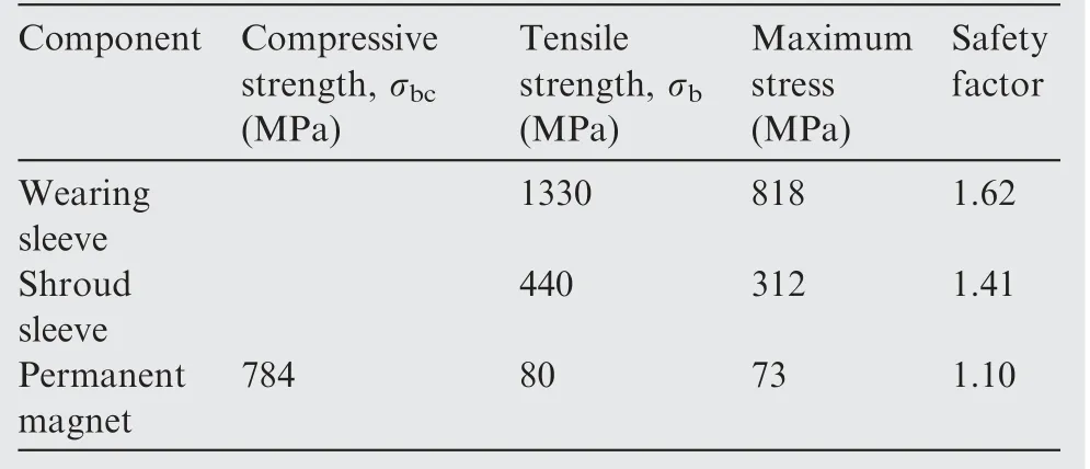
Table 6 Strength safety factor and yield strength.
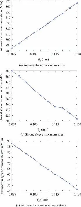
Fig.14 Maximum stress variation with δs1.
5.Multi-objective optimization of motor rotor of MSPMSM
The thermal-structure coupling analysis results indicate that the shroud sleeve and permanent magnet with much lower strength safety factors do not meet the design requirements.Therefore,it is necessary to optimize the structure of the MSPMSM rotor in the design process to ensure its stability and service life.
5.1.Optimization scheme

Fig.15 Maximum stress variation with initial clearance.
A long life and high stability of the MSPMSM rotor are expected,so the strength safety factors of the components are chosen as the optimization objectives.According to the mathematical model and finite element analysis results,the dimensions and the interference δs1are closely related to the stresses of the rotor,of which the outer diameters of the permanent magnet and wearing sleeve have been determined by the magnetic flux density requirement and the volume of MSPMSM respectively.So,the nominal diameter d1,the inner diameter of the permanent magnet d2and the interference δs1can be taken as the optimization variables.The optimization mathematical model built based on the requirement of strength is expressed as follows:
Max f(X)
Constraint conditions are as follows:

where f(X)is the optimization objective function and f(X)=x1+x2+x3;x1,x2and x3represent the strength safety factors of the shroud sleeve,wearing sleeve and permanent magnet respectively.
In this paper,the method combining the multi-disciplinary design optimization(MDO)platform iSIGHT and ANSYS is applied to the optimization design.Since the thermal-structure coupling is a nonlinear system,Sequential Quadratic Programming Non-Linear Programming by Quadratic Lagrangian(SQP-NLPQL)is selected because of its superiority for the nonlinear and multi-objective optimization.
Firstly,we establish the finite element analysis system of the rotor stress in the ANSYS platform,set the range of the rotor optimization variables x1,x2and x3,and create the optimization objective function f(X)at the iSIGHT platform.
Secondly,we input the rotor variables that meet the set scope to the finite element analysis system of the rotor stress,including the dimensions d1,d2and the interference δs1.Optimized variables x1,x2can be obtained by the thermal-structure coupling analysis,and optimized variable x3can be obtained by the mechanical analysis.
Thirdly,we input the optimized variables x1,x2and x3to the ISIGTH,and call the algorithm of SQP-NLPQL to iterate and optimize.If the optimization objective function f(X)is not optimal and variables are not satisfying constraint condition,we change the value of the motor rotor variables d1,d2and δs1with a small step and re-input them to the finite element analysis system of the rotor stress.The cycle operation is performed until the optimization objective function f(X)reaches an optimal value.The optimization flow diagram is shown in Fig.16.
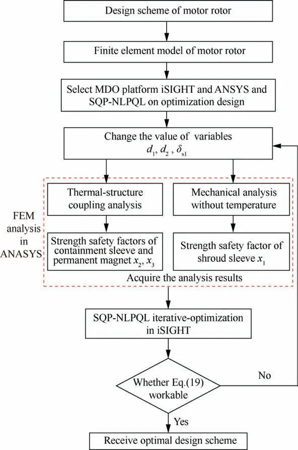
Fig.16 Optimization flow diagram.
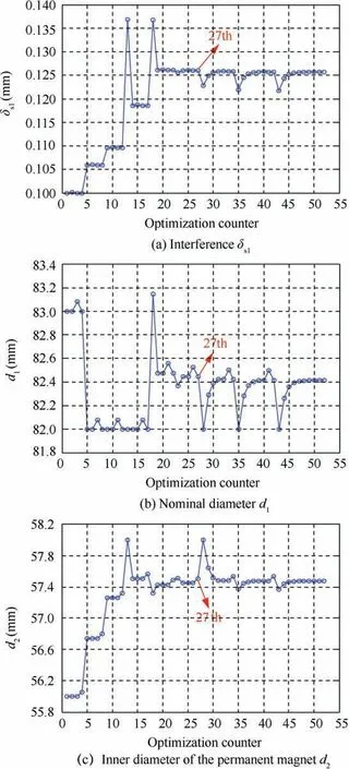
Fig.17 Optimization process of variables.
5.2.Optimization result
Figs.17 and 18 show the variation of the optimization variables and the optimization objectives.The optimization process iterates 52 steps in total with the optimal result appearing in the 27th step.The optimal result is shown in Table 7.
Originally,the shroud sleeve and permanent magnet bear the high stresses,resulting in their lower strength safety factors,especially the permanent magnet,as the core component of the motor rotor,whose strength safety factor is just 1.1.So,it is easy for the permanent magnet to damage under the impact of the high speed and temperature.Through optimization,the strength safety factors of the components all achieve demand,of which the strength safety factor of the permanent magnet has more than doubled compared with the initial one,which ensures that it can perform securely in the operating state. The stress distribution of the components in the MSPMSM rotor after optimization is shown in Fig.19,which obviously decreases compared with the initial one(see Figs.11 and 12).
6.Experiment
According to the above optimization result,the optimized rotor is fabricated and assembled,as shown in Fig.20.The two same manufactured prototypes of MSPMSM with the optimized rotor are connected together at their ends by the flexible coupling to perform the back-to-back tests.Among them,one prototype is the driving motor,and the other serves as a generator,which are shown in Fig.21.The measured motor is the driving motor,which is sped up to 32,000 r/min with a power of 100 kW.The driving motor is driven by an IGBT based voltage source inverter to adjust the speed.The generator works as a load with its output to a three-phase power resistance box.The three-phase power resistance box is also shown in Fig.21.In the experimental setup,the speed is measured by the displacement sensor in the driving motor,and the power is measured by the three-phase power resistance box connected to the generator.From the three-phase power resistance box,we can measure the voltage and current flowing through each phase.Through simple power calculation,we can get the output power.The measured voltage and current in each phase of the three-phase power resistance box are respectively 179 V-187 A,179 V-186 A and 178 V-187 A,and the measured output power is approximatively 100 kW.An external chilled-water unit provides cycled cold water which flows through the cooling water passage between the inner and outer enclosures of the machine.An external air blower forces the ambient air through the air gap in the driving motor.
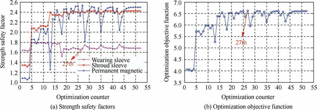
Fig.18 Optimization process of optimization objectives.
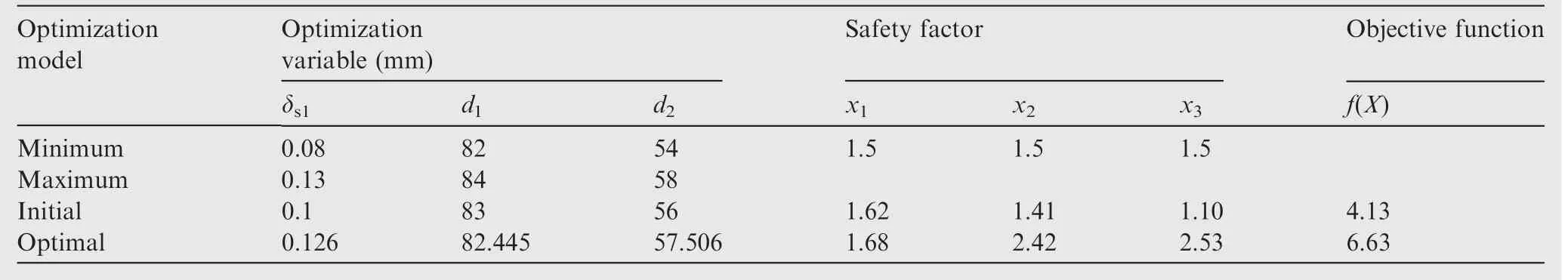
Table 7 Optimal results.

Fig.19 Stress distribution of components after optimization.

Fig.20 Manufactured prototype of MSPMSM rotor.
Fig.22 shows displacement signal waveforms and experimental speed data of the driving motor's high-speed rotor measured by scope,which is driven by the MSPMSM with rotation speed of 32000 r/min and power of 100 kW.The high-speed rotor is radially supported by both A end and B end RMB(see Fig.1),and its radial position can be detected by the eddy-current displacement sensors located beside each RMB.The Ax and Ay,Bx and By in Fig.22 represent the radial displacements obtained by A end and B end displacement sensor(see Fig.1)along x-axis and y-axis direction,respectively.In the frequency spectrum of the displacement sensor signal,the amplitude is maximum(peak)at the same frequency as the rotating frequency because the disturbance caused by the imbalance of the rotor is large at the rotating frequency.Therefore,for the tested driving motor in this paper,534 Hz measured by scope is the same as rotating frequency of the rotor,which means that the machine is running at 32000 r/min.When the driving motor runs up to 32000 r/min(534.1 Hz in Fig.22),the maximum peak-peak value of the rotor radial displacements is 36.8 μm(as shown in Fig.22),which is less than the protective air gap 0.3 mm of the driving motor.This means that the rotor can normally speed up to 32000 r/min and stably run a long time under 100 kW load condition.

Fig.21 Back-to-back test setup of two MSPMSM prototypes.
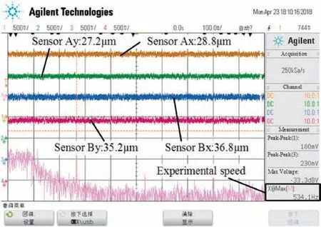
Fig.22 Displacement signal waveforms of driving motor with rotation speed of 32,000 r/min.
When the driving motor is running,the optimized rotor of the motor maintains a high-speed rotation state.So,it is hard to place temperature sensors to measure the temperature of rotor directly.To verify the correctness of temperature simulation analysis,five Pt100 resistance thermometer sensors are placed at different locations of the driving motor,as shown in Fig.23,including radial magnetic bearing winding,axial magnetic bearing winding,outer enclosure,motor stator core and motor windings.The Pt100 we used has a measuring accuracy of±0.1°C and a measuring range from-50°C to 250°C. The temperature inspecting instrument shown in Fig.21 switches each Pt100 input signal through the multichannel electronic switch and displays the access signal one by one.
After the driving motor runs to a stable speed,it continues working for a period to achieve the thermal steady state.The steady temperature values of every Pt100 are read from the screen of temperature inspecting instrument.Table 8 lists the measured steady temperature values at every location and also the temperature simulation value of the corresponding position.
The temperature measurement of the driving motor winding is 80.1°C,as shown in motor winding 5[see Fig.23],and the temperature simulation value of the correspondingposition is 82.4°C.The error between the value of the simulation and the measured one in the motor winding is 2.8%.The temperature of the motor stator core is 71.3°C as shown in motor stator core 4 with an error 2.3%between the measured one and simulated one.The temperature of the radial magnetic bearing winding measured by RMB winding 1 is 40.2°C,with an error 3.6%compared with the simulation value 41.7°C.And the temperature of axial magnetic bearing winding is 37.4°C with an error 3.1%compared with the simulation value 38.6°C.The temperature of outer enclosure is lower,the temperature measurement is 29.6°C,the temperature simulation value of the corresponding position is 30.8°C,and the error between the measurement and the simulation value is 3.9%.

Table 8 Experiment results.
Comparison of experimental results with simulation values shows that the temperature measurement agrees well with the value of 2D FEM simulation.
7.Conclusions
In this paper,the thermal-structure coupling analysis and multi-objective optimization of motor rotor in MSPMSM are proposed to analyze and reduce the influences of rotor's mechanical properties caused by the temperature rise problem as well as ensure the strength safety.Some conclusions can be summarized as follows:
1)The temperature analysis of the MSPMSM exhibits that the motor rotor will reach the highest temperature 86.5-98.2°C in the thermal steady state. Moreover, the method of applying the temperature result calculated by 2D finite element model to the 3D one equivalently is reasonable.
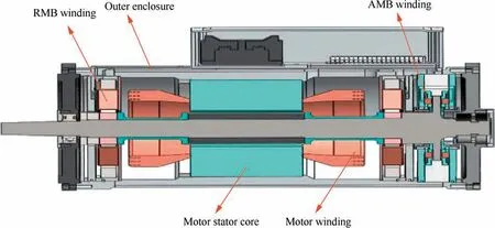
Fig.23 Experimental measurement of temperature in driving motor.
2)The thermal-structure coupling analytical result calculated through the precise finite element model indicates that the temperature field does not always do damage to the strength of the components.On the one hand,it increases the stress of the wearing sleeve and permanent magnet;on the other hand,it decreases the stress of the shroud sleeve.
3)The effect produced by the interference and initial clearances on the strength of the components is analyzed and the result illustrates that with the increase of the interference,the strength of the shroud sleeve and permanent magnet increases, and that of the wearing sleeve decreases, whereas the initial clearances have little impact on their strength.
4)Optimization results based on the iSIGHT and ANSYS display that all the components achieve the design requirement of mechanical strength.Through optimization,the strength safety factor of the shroud sleeve increases by 71.6%,and the strength safety factor of the permanent magnet has more than doubled compared with the initial one.
Acknowledgements
This work was co-supported by the Excellent Youth Science Foundation of China(No.51722501),the China Postdoctoral Science Foundation(No.2016M600027),the National Natural Science Foundation of China(Nos.51575025 and 61703022),and the Preliminary Exploration of Project of China(No.7131474).
 CHINESE JOURNAL OF AERONAUTICS2019年7期
- CHINESE JOURNAL OF AERONAUTICS的其它文章
- Guide for Authors
- Prediction of cutting forces in flank milling of parts with non-developable ruled surfaces
- Configuration synthesis of planar folded and common overconstrained spatial rectangular pyramid deployable truss units
- A new error-controllable method for smoothing the G01 commands
- Electrochemical trepanning with uniform electrolyte flow around the entire blade profile
- Lightweight structure of a phase-change thermal controller based on lattice cells manufactured by SLM