A Ply-By-Ply Discretized 2D FEA Approach with the Integrated XFEM-CE Strategy for Predicting Multiple Failures in Laminated Composite Structures
,
Abstract: Delamination and matrix cracking are two common failure mechanisms in composite structures, and are usually coupled with each other, leading to multiple failures pattern. This paper proposed a fast damage prediction methodology for composite laminated structures based on the ply-by-ply 2D (two dimensional) FE model of composite laminates in the transverse plane. The layer-wise 2D FE model was firstly used in conjunction with the integrated XFEM/CE strategy, which simulated the interface delamination with cohesive elements and the intra-ply matrix crack with XFEM (extended finite element method). To realize ply-by-ply 2D FE (finite element) modeling of composite laminates, two 2D material models were developed based on the plane stress assumption and plane strain assumption, respectively. A general crack propagation scheme was developed in the framework of the integrated XFEM-CE method. Adopting the 2D material model based on the plane strain assumption, a ply-by-ply discretized 2D FEA procedure was conducted for an out-of-plane composite Pi joint under the static tensile load.The predicted load-displacement response and damage evolution process showed good agreement with the experimental results, which verified the proposed approach.
Keywords: Composites, laminate, strength, finite element analysis.
1 Introduction
Carbon fiber reinforced resin matrix composite laminates are used extensively in large aircrafts, experience complex load, including: impact, hyperthermia, hygrothermal and fatigue load [Wang, Zhao, Hong et al. (2018); Zhao, Yang, Cao et al. (2018); Zhang, Qi,Zhou et al. (2015); Zhang, Zhao, Li et al. (2015)]. There are three principle failure mechanisms for composites, which are fiber failure, matrix cracking, and delamination[Davies and Rajapakse (2013); Zhao, Li, Zhang et al. (2018); Zhi, Zhao, Zhang et al.(2016); Zhang, Zhou, Chen et al. (2016); Qin, Zhao, Xu et al. (2019); Swati , Wen , Elahi et al. (2018); Lu, Chen, Tan et al. (2018)]. Actually, in real composite structures the matrix cracking and delamination are usually coupled. The matrix cracking and delamination always do not occur alone but have a strong interaction associated with each other [Sane, Padole and Uddanwadiker (2018); Sun, Chang, Wang et al. (2018);Gong, Zhao, Zhang et al. (2018a); Gong, Zhao, Zhang et al. (2018b)]. This interaction represents as a coupling phenomenon that the initiated matrix cracking can cause delamination and significantly affect its propagation. Meanwhile, the delamination between two adjacent non-zero angle plies may evolve to seriously matrix damage.
In early studies, the matrix cracking and delamination processes were dealt separately with different theories: the delamination were often analyzed using either LEFM [Tay(2003)] or cohesive zone models (CZMs) [Farmand-Ashtiani, Alanis, Cugnoni et al(2015)], while continuous damage mechanics (CDM) based on the strength-based criteria was used for the matrix cracking [McCartney (2003)]. However, the CDM used to model the matrix damage is not a realistic method, because it cannot deal with highly concentrated crack-like damage which is often happened during matrix cracking. In recent years, the XFEM (extended finite element method) has obtained widely application in simulating intra-ply matrix cracks for its capacity in simulating crack growth along an arbitrary path [Zeng, Liu, Xu et al. (2015); Zhao, Zhi, Zhang et al.(2016); Grogan, Leen and Bradaigh (2014); Tay, Sun and Tan (2014)]. Recently, an integrated XFEM-CE approach was proposed by Tay et al. [Tay, Sun and Tan (2014)],and has been widely used [Li and Chen (2016a); Li and Chen (2016b); Li and Chen(2016c)]. The integrated XFEM-CE approach uses XFEM to simulate the intra-ply matrix cracks and CZMs to model the delamination which use CEs (cohesive elements) to model interfaces. The competition between cohesive elements driven and XFEM driven propagation can well model the interaction and mode transformation between the matrix cracking and delamination. And the integrated XFEM-CE method has achieved a good efficacy in modeling the interactions of matrix cracking and delamination in laminated composite structures [Farmand-Ashtiani, Alanis, Cugnoni et al. (2015); Grogan, Leen and Bradaigh (2015); Bouhala, Makradi, Belouettar et al. (2015); Vigueras, Sket, Samaniego et al. (2015); Hu, Chen, Tirvaudey et al. (2016); Shi and Lua (2010)].Compared with the previous method, the XFEM-CE method can address the realistic issues of the complex mechanism for the coupling phenomenon of the matrix cracks and delamination [Tay,Sun and Tan (2014); Tay, Sun and Tan (2012)]. However, the computational cost and calculation convergence difficulty increase significantly as well, especially when the integrated CE-XFEM strategy is applied to a 3D (three-dimensional) FE model. In fact,in many cases, the actual composites structures can be simplified to a 2D FE model in the transverse plane of the structure based on the plain strain assumption or the plain stress assumption. Thus, there is an urgent need of seeking for a fast 2D FEA approach with a reasonable accuracy and low computational cost for the composites structures designers.However, a big difficulty facing the building of a 2D FE model of the laminated composite structures in the transverse plane lies in its laminated structures, as the composite laminates are consist of laminas with different fiber orientations [Jiao and Fish(2015)]. In early studies on 2D FEA of composite structures, the laminates were always modeled as a homogeneous body, and the effective material properties calculated according to the Classical Laminate Theory were used to build the FE model [Tsai,Morton and Matthews (1995); Randolph and Clifford (2004)]. This modeling method is unable to obtain the stress distribution within each single layer and the interlaminar stress,thus it cannot predict the intra-ply damage in the layer level and the delamination in composite structures. Besides, the plies with different fiber orientations are different from each other in mechanical property with reference to the global coordinate system. Thus the 2D FE model of the laminated composite structures in the transverse plane should adopt a ply-by-ply modeling strategy. During ply-by-ply modeling of every composite lamina in the 2D FE model, the material properties in the plane element (such as plane stress element or plane strain element) are hard to set, because the fiber directions of different plies are oblique and have deflexion angles referred to the element plane. To surmount this difficulty, two 2D material models were developed in this paper based on the plane stress assumption and the plane strain assumption, respectively. The two 2D material models could provide a group of equivalent material constants for every single composite ply needed for building 2D FE model of composite laminates in the transverse plane. The layer-wise 2D FE model can be well used in conjunction with the integrated XFEM/CE strategy, which would realize the simulation of delamination coupled intra-ply matrix crack in laminated composite structures.
The purpose of this paper is developing a fast damage prediction methodology for the complicated matrix cracking coupled delamination behavior in composite laminated structures based on the ply-by-ply 2D (two dimensional) FE model of composite laminates in the transverse plane. The approach proposed in this paper first combines the ply-by-ply discretized 2D FE modeling technique based on the proposed 2D material model with the integrated XFEM-CE strategy. This paper is organized as follows. In section 2, a ply-by-ply discretized 2D FEA approach with the XFEM-CE method was developed to predict the matrix crack and delamination coupled damage mechanism in laminated composite structures. Two 2D material models of composite lamina for ply-byply 2D FE modeling of composite laminates were proposed. A general crack propagation scheme based on the integrated XFEM-CE strategy was developed. Section 3 shows the applications of the ply-by-ply discretized 2D FEA approach with the integrated XFEM-CE strategy in predicting mechanical properties of an out-of-plane composites Pi joint. The predicted load-displacement response and the damage evolution process were compared with the experimental results, and the detailed mechanism of matrix cracking coupled delamination was discussed. The numerical examples proved the capability and effectiveness of the proposed approach. Section 4 summarizes the conclusions for this paper.
2 Ply-by-ply discretized 2D FEA approach with the integrated XFEM-CE strategy
In this section, a ply-by-ply discretized 2D FEA approach with the XFEM-CE method was developed to predict the matrix crack and delamination coupled damage mechanism in composite structures. This approach includes a 2D FE modelling technique through ply-by-ply modelling for each composite ply, and a general crack growth simulating scheme with the integrated XFEM-CE strategy. To realize the ply-by-ply modelling for the 2D FE model of composite laminated structures in the transverse plane, two 2D material models were proposed which provided a group of equivalent material parameters needed by 2D FE modelling for composite plies with different fiber orientations.
2.1 Two 2D material models for ply-by-ply modeling laminate in transverse plane
The two material models were developed according to different hypotheses when simplifying a 3D problem into a 2D problem. The first model was based on the plane stress assumption, which could be used in mechanical analysis for a plane where the outof-plane stress components could be ignored, for example, the front and rear faces of the composite laminates in the transverse direction. The other model was based on the plane strain assumption which could be used in mechanical analysis for a plane where the outof-plane strain components could be ignored, for example, the transverse middle plane of the composite laminates [Zhao, Wang, Qin et al. (2014)].
2.1.1 Material model based on the plane stress assumption
Fig. 1(c) illustrated a single ply isolated from composite laminate comprising a stack of plies with different fiber directions as shown in Fig. 1(a). The natural coordinate system of a lamina with three principal axes: 1 (longitudinal, fiber direction), 2 (transverse direction) and 3 (interlaminar direction) can be rotated to the Cartesian coordinate system O-XYZ which is a global coordinate system of the whole laminate with X-axis, Y-axis and Z-axis respectively along the length, the width and the thickness direction of the laminate.
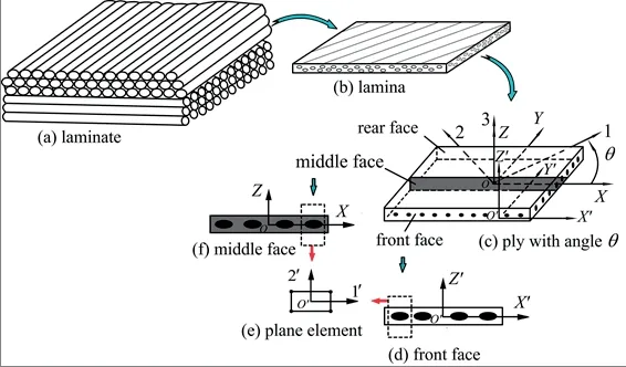
Figure 1: Illustration for the two material models based on the assumption of plane stress/strain
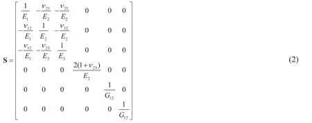
According to the orthotropic elastic mechanics theory, a single composite ply can be assumed as transversely isotropic materials in the principal coordinate system O-123,thus the material constitute relationship can be expressed as

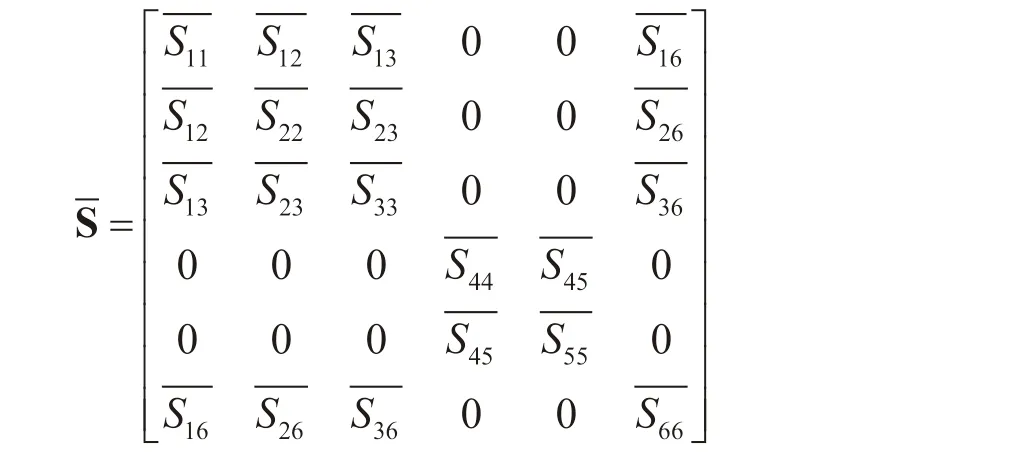
If change the reference coordinates system from the principal coordinate system O-123 to the global coordinate system O-XYZ, new compliance matrix is required to relate the stresses components and the strains components [Kollar and Springer (2009)]

whereand
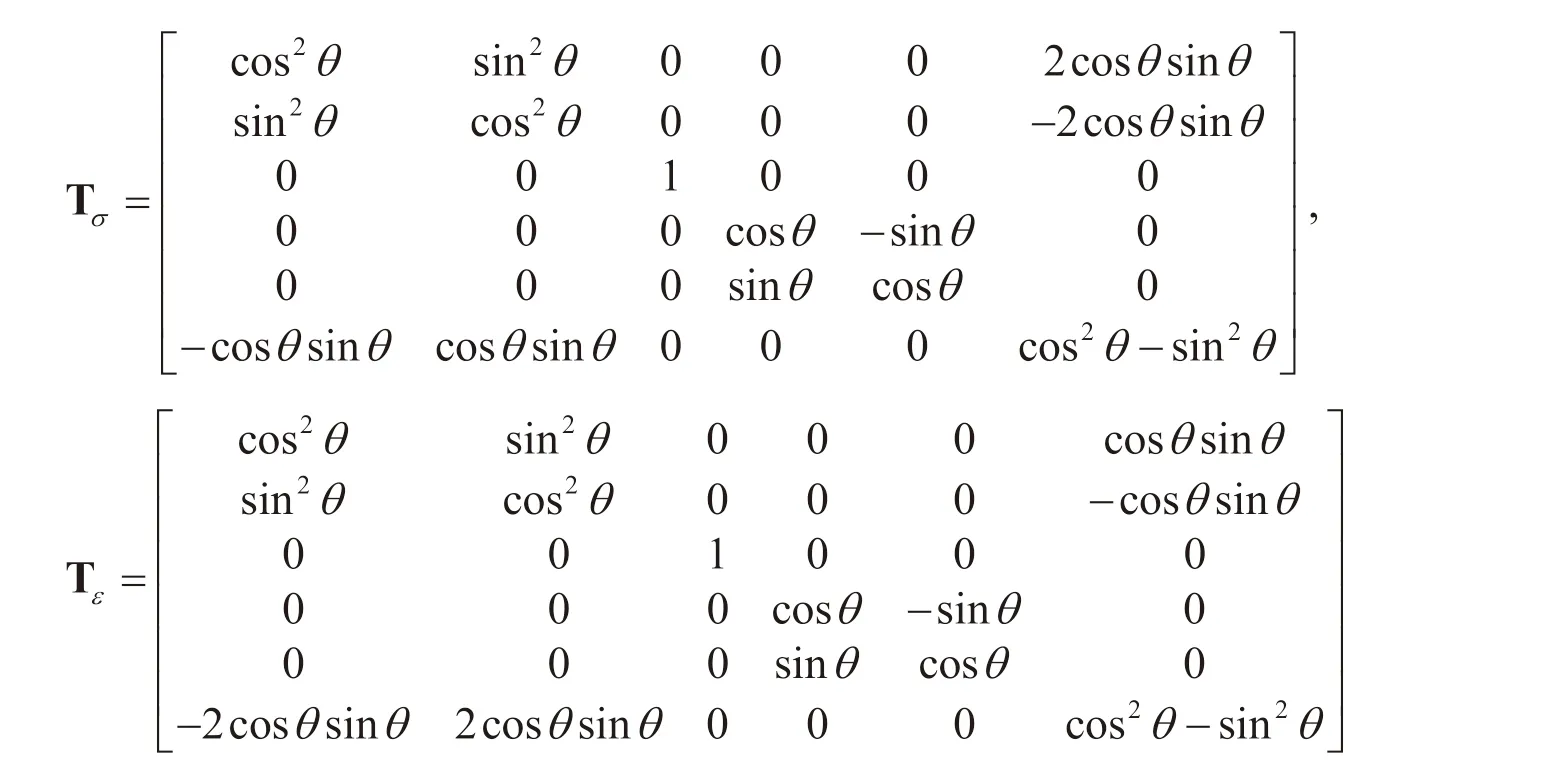
Introduce the stress transformation matrix Tσand the strain transformation matrix Tεbetween the principal coordinate system O-123 and the global coordinate system O-XYZ,and consider the strain-stress relationship shown in Eqs. (1) and (3), the compliance matrixreference to the coordinate system O-XYZ can be derived from the compliance matrixSreference to the principal coordinate system O-123.

where the elements in matrixσT andεTcan be expressed as the trigonometric function of the ply angle θ which is defined as the angle between the X-axis and the 1-axis.
Moving the global coordinate system O-XYZ of the whole laminate from the transverse middle plane of the ply to the front face of the composite ply, as illustrated in Fig. 1(c), a new coordinate system is obtained, which is denoted as O′-X′Y′Z′. As no dependence of the constitute relation on the original point of the coordinate systems exists, the strainstress relations with reference to the global Cartesian ordinate system O-XYZ and O′-X′Y′Z′ are the same, as shown in Eq. (3). As seen from Fig. 1(d), in the transverse front face of the composite ply, which is a free face, the plane stress condition is satisfied

Imposing the above condition to Eq. (3), the following equation sets can be obtained

Taking the strain components, such as εx, εz, γxz, as the known quantities, the stress components σx, σz, τxzcan be uniquely determined by the combination of the first, third and fifth equation from the above equation sets (6), and following strain-stress relation can be obtained.

The strain-stress relationship with reference to the coordinate system X′-O′-Z′ shown in Eq. (7) can be applied to define the material constitute relation for the 2D plane element in the transverse front face of the composite ply.
In the 2D plane element with a local coordinate system O′-1′2′ as shown in Fig. 1(e), the stresses components in the element can be calculated from the strains components with the following constitute relation

Inversing Eq. (8) and introducing a group of equivalent engineering constantsandwith reference to the element local coordinate system O′-1′2′, the strain-stress relation in the element can be expressed as

Contrasting Eq. (9) with Eq. (7) and making the compliance matrix elements in the above two equations equal to each other, the following relations can be obtained

2.1.2 Material model based on the plane strain assumption
When taking the middle plane in the transverse direction of the composite ply for analysis,the middle plane in the transverse direction of the composite laminate satisfies the plane strain condition. According to the plane strain assumption, the out of plane strain of composite ply in the X-O-Y plane of the composite ply is zero

Inverting Eq. (3),can be expressed as

where
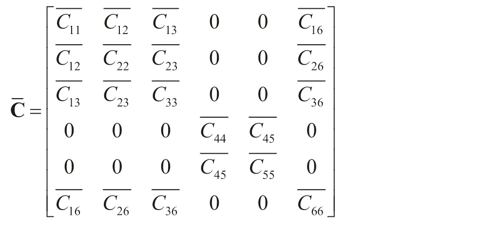
Enforcing the above plane strain condition in Eq. (11) to Eq. (12), the constitute relation in the X-O-Z plane in the transverse middle plane, as shown in Fig. 1(f), reduces to

Inverting Eq. (13), the strains in the X-O-Z plane can be expressed as

where the compliance matrix comprising elements of(i, j=1, 2, 3) can be obtained by inverting the stiffness matrix which is comprised ofas shown in Eq. (13).The strain-stress relationship shown in Eq. (14) can be applied to define the material constitute relation for the 2D element in the transverse middle plane.
Contrasting Eq. (14) with Eq. (9) and making the compliance matrix elements in the above two equations equal to each other, the following relations can be obtained

2.2 A general crack propagation scheme based on integrated XFEM-CE strategy
The general crack propagation scheme based on integrated XFEM-CE strategy includes the simulation scheme of matrix cracking with XFEM, and the simulation scheme of delamination with the cohesive elements (CEs).
(1) Simulation scheme of matrix cracking with XFEM
The matrix can be treated as an isotropic material, so the maximum principal stress criterion was adopted as the crack initiation criterion, and the crack-growth direction was specified to be orthogonal to the maximum principal stress direction. Besides, as the crack growth within matrix is similar to that in isotropic material, which is prone to become a mode I dominated fracture behavior [Ratcliffe, Czabaj and O'Brien (2013);Ratcliffe and De Carvalho (2014)], herein, a pure mode damage evolution law was adopted in this paper to govern the matrix crack propagation.
The maximum principal stress criterion adopted to indicate the matrix crack initiation within composites ply is expressed as:

The pure mode fracture criterion which is adopted to govern the matrix crack propagation is expressed as:

where G is the energy release rate in front of the matrix crack tip, and Gcis the critical fracture toughness of the matrix.
(2) Simulation scheme of delamination with the cohesive elements (CEs)
The interlaminar interface was modelled using the cohesive elements (CEs) to simulate delamination.The delamination in composite structures is always a mix-mode one, thus a quadratic nominal stress criterion was used as the delamination initiation criterion, and the B-K fracture criterion was adopted to govern the delamination growth.
As for the simulation of delamination with the CEs, the quadratic nominal stress criterion used as the crack initiation criterion is expressed as:

where tnandare the interlaminar normal stress and the transverse tensile strength,respectively; tsandare the interlaminar shear stress and transverse shear strength,respectively.
The mixed-mode delamination process was governed with a B-K law:

where G is the energy release rate corresponding to delamination. GIc, GIIcand η are the specified material parameters. β is the mode mixture ratio, which is expressed as β=GII/(GI+GII).
3 Numerical applications
The ply-by-ply discretized 2D FEA approach with the integrated XFEM-CE strategy proposed in this paper was applied to a complex out-of-plane cohesively boned composite joint with a ‘‘Pi'' shape configuration.
3.1 Configuration and load condition of an out-of-plane composite Pi joint
Fig. 2 shows the detailed configuration and dimension of the composite Pi joint. A Pi shaped overlaminate was co-bonded with a horizontal skin, and then secondary-bonded with a vertical web plate. The Pi shaped laminates are comprised of two L shaped prepregs and a U shaped prepreg made of carbon/bismaleimide composites. Each L shaped prepreg and U shaped prepreg comprise of 3 plies of UD-CFRP (unidirectional carbon fiber reinforced plastics) with a stacking sequence of -45°/0°/45°. The two deltoid regions surrounded by the Pi shaped laminate and skin were fabricated with the same UD-CFRP with its fiber direction along the width direction of the Pi joint. The skin and web were fabricated with sandwich panels, with 8 plies of UD-CFRP on both sides serving as the face sheet. The core of the skin was made of GFRP (glass fiber reinforced plastics). The core of the web included two materials: the part with a length of 50mm downwards from the top of web was made of GFRP and the rest part was made of Nomex honeycomb. The lay-ups of the face sheet of the web and the skin are [90°/90°/-45°/45°]Sand [-45°/0°/45°/90°]S. The material properties of the unidirectional prepreg are:E1=121 GPa, E2=E3=7.46 GPa, v12=v13=0.31, v23=0.5, G12=G13=5.18 GPa, G23=2.49 GPa,Xt=2326 MPa, Xc=1236 MPa, Yt=Zt=51 MPa, Yc=Zc=209 MPa, S12=87.9 MPa, S23=99.2 MPa [Zhang, Zhao, Qin, et al. (2014)].
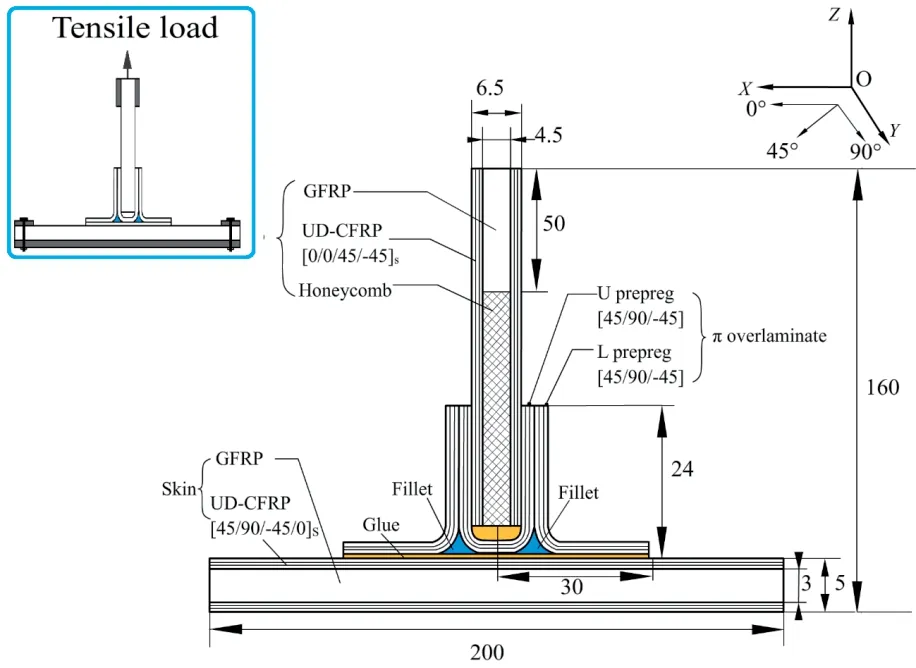
Figure 2: Configuration and load condition of the composite joint
Five specimens of the Pi joint were tested under tensile load. The Pi joint was mounted to the testing machine with two rigid plates clamping both ends of skin plate and, then the two rigid plates were bolted to the rigid bracket. The distance between the centers of the two rigid plates was 160mm. The tensile tests were conducted in servo hydraulic testing apparatus (INSTRON 8803) in a displacement control mode with a constant displacement rate of 1 mm/min. During the test load-displacement curves were recorded.
3.2 Ply-by-ply discretized 2D FEA with XFEM-CE strategy for a composite bonded Pi joint
3.2.1 Ply-by-ply discretized 2D FE model for composite bonded Pi joint
On account of the symmetrical loading condition and configuration of the composite Pi joint, a 2D FE model for the transverse plane of the structure can well reflect the response of the composite Pi joint with the plane strain assumption. Thus, the 2D material model, as shown in Section 2.1, based on the plain strain assumption were chosen to calculated the equivalent engineering constants for each composite ply in the 2D FE model of the Pi joint.The 2D FE model was built for the composite Pi joint in the commercial software ABAQUS®, in which each composite ply was assigned with the material properties (a group of equivalent engineering constants) from the 2D material model based on the plain strain assumption. The 2D FE model of the composite Pi joint was established through a ply-by-ply modeling strategy for each composite ply by employing the 2D equivalent engineering constants of plies with different fiber orientations calculated with the chosen 2D material model as listed in Tab. 1.
The 2D FE model with constraint conditions is shown in Fig. 3. The CPE4 (4-node bilinear plane stress quadrilateral element) was chosen for each composite lamina in the 2D FE model of the composite Pi joint. In the 2D FE model of the Pi joint, each composite ply was modelled with one element through the thickness direction. According to the previous study [Zhang, Zhao, Qin et al. (2014); Zhao, Qin, Zhang et al. (2013);Zhao, Qin, Chen et al. (2014); Zhang, Shan, Zhao et al. (2015)], the deltoid region which included the double fillers and critical interfaces (marked with red line as shown in Fig. 3)around the double fillers was a critical part of the Pi joint. And the damage pattern of the Pi joint was the combination of the matrix cracking within the double fillers and the delamination around the two deltoid regions. Thus a refined a uniform mesh size of 0.05 mm in the length direction was chosen for each composite ply within the region close to the deltoid region (the region in the black dotted frame as shown in Fig. 3) to capture accurate stress distributions. While, relatively coarse meshes (a uniform mesh sizes of 1mm) were adopted in regions far away from the deltoid region for the purpose of saving computational cost. The damage mechanism of the critical interfaces was delamination,and the damage pattern of the two double fillers was matrix cracking. So, the cohesive element was adopted to model the critical interfaces and XFEM was used to simulate the matrix cracks propagation in the two double fillers. A layer of COH2D4 elements with a thickness of 0.005 mm and a length of 0.02 mm was chosen for modeling the critical interfaces in the Pi joint. The CPE4 elements with a size of 0.05 mm were adopted at two fillers, and the elements were enriched for XFEM simulation. The total numbers of the elements and the nodes in the 2D FE model are 12988 and 13402, respectively. In order to simulate the true clamping condition, the top and bottom faces of the skin in the 2D FE model with a distance of 20 mm in length from two edges were constrained. Set a reference point A on the top face of the FE model of the Pi joint, and assign a “tie”constraint between the reference point A and the top face, so the point A and all the nodes on the top face will have the identical degree of freedom. Then exert a displacement of 5mm on the point A along the Z-axis direction to simulate the true tensile loading conditions during the experiment.

Table 1: Equivalent engineering constants from material model based on plane strain assumption

Figure 3: FE model of the composite Pi joint
3.2.2 Crack propagation model for Pi joint with the integrated XFEM-CE strategy
In the ply-by-ply discretized 2D FE model for composite bonded Pi joint built in the above section, the cohesive elements were adopted to model the critical interfaces and the XFEM technique was used to simulate the matrix cracks propagation in the two double fillers. Herein, the general crack propagation scheme based on the integrated XFEM-CE strategy for composite laminates represented in Section 2.2 can be applied in simulating the crack propagation within the Pi joint.
(1) Parameters used in XFEM simulation scheme for matrix crack propagation
For the parameters used in XFEM simulation scheme for matrix crack propagation in double fillers, the allowable value of the maximum principal stressof the matrix in Eq. (16) was set with the value of in situ transverse tensile strengthof the unidirectional prepreg. According to the study of Camanho et al. [Camanho, Dávila,Pinho et al. (2006)], the value ofwas calculated, and its value is 85 MPa. As the fracture toughness corresponding to mode I delamination initiation mainly depends on the matrix, so the fracture toughness value of the matrix Gcused in the pure mode fracture criterion governing the matrix crack was thought to be equal to GIcof the carbon/bismaleimide composites. The value of GIcof carbon/bismaleimide composites is 0.252 N/mm, so the Gcused in Eq. (17) is set with the above value.(2) Parameters used in delamination simulation scheme with the CEs Based on the study on the parameter scheme for interface strength [Zhao, Gong, Zhang et al. (2014)], the recommended interface strength value used in CEs is slightly lower than the corresponding interlaminar strength. So interface strength values chosen for the CEs modelling the critical interfaces of the composite Pi joint in Eq. (18) were=40 MPa and= 70 MPa . Refer to the study from Zhao et al. [Zhao, Gong and Qin (2013)], the values of the mode I and mode II delamination fracture toughness in Eq. (19) were GIc=0.252 N/mm and GIIc=0.665 N/mm. Besides, according the previous study, the exponent used in the B-K fracture criterion for the fiber reinforced composite material depends on whether the resin is brittle (η=2) or ductile (η=3) [Benzeggagh and Kenane(1996)]. Considering the bismaleimide resin is ductile, so exponent η used in the B-K fracture criterion in this paper is η=3. According to the recommended parameter scheme from the study of Motamedi et al. [Motamedi and Milani (2013)], the values of penalty stiffness used in current work are: Knn=Ktt=105N/mm3. A viscosity coefficient of 10-5was used to improve the capacities of computational convergence.
3.3 Result and discussion
3.3.1 Load-displacement response
Load-displacement curves of the composite Pi joint under tensile load were obtained both from the experiments and numerical simulation. The comparison was illustrated in Fig. 4.The red line with a five-pointed star indicates the load-displacement curve predicted by the numerical simulation with the proposed ply-by-ply discretized 2D FEA approach with XFEM-CE strategy. The other five lines are the tested load-displacement curves of the five Pi joint specimens. The load increases linearly with the displacement until the maximum load, and then the load decreases sharply, indicating the ultimate failure of the Pi joint. The predicted stiffness of the Pi joint is well among the stiffness of the five Pi joint specimens. The ultimate loads of five specimens and the predicted ultimate load are listed in Tab. 2 for comparison. The mean value of experimental ultimate loads Ptof the five Pi joint specimens is 3.60 kN, and the coefficient of variance (C.V.) is 7.70%. The predicted ultimate load Psis 3.70 kN, so the error between the prediction and experimental average ultimate load is 2.78%, which is within the C.V. of the test results.Herein, the predicted load-displacement response of the composite Pi joint is in good agreement with experimental results.
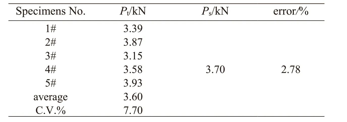
Table 2: Ultimate loads of five specimens and the predicted ultimate load from FEA

Figure 4: Comparison of tensile load-displacement curves of composite Pi joint between numerical simulations and experiments
3.3.2 Damage evolution process
Fig. 5 and Fig. 6 show the damage evolution process of the composite Pi joint observed in the experiment and obtained from the numerical simulation, respectively. A schematic simulated crack propagation process within the composite Pi joint is illustrated in Fig.6(a), where the red points represent the damage onset locus during the typical fracture events ordered with the numbers (①-④) in chronological order, and the blue arrows extending from every red point represent the damage propagation direction.
As seen from Fig. 5(a) and Figs. 6(b)-6(c), the experimental observation and simulation of the crack initiation are similar. The first visible crack (delamination) onset occurred at the interface between the U shaped laminate and the double fillers. The delamination at the interface led to the stress transmission into the double fillers, and eventually yielded the macroscopic matrix crack in the double fillers. Subsequently, from the observation during experiment illustrated in Fig. 5(b), the crack at the interface continued to grow in both the forward and backward directions simultaneously. Meanwhile, the crack within the fillers region propagated downward and grew towards the bonding interface adjacent the skin. The above crack propagation process observed during the test was well captured by the simulation, as can be seen in Fig. 6(d). The eventually damage morphologies of the composite Pi joint from the experimental observation and simulation are illustrated in Fig. 5(c) and Fig. 6(e), respectively, which shows a good agreement. The crack propagated into the bonding interface above the skin and eventually led to the final failure of the Pi joint. Besides, a new crack was also observed at the interfaces between the two fillers and the L shaped laminates. In summary, it can be seen that the proposed ply-by-ply discretized 2D FEA approach with XFEM-CE strategy can provide a good prediction for the damage evolution process in the Pi joint.According to the above comparison of experiment and numerical simulation, the predicted load-displacement response and damage evolution of the composite Pi joint showed a good agreement with the experimental results. Besides, the proposed ply-by-ply discretized 2D FEA approach showed an excellent computational efficiency. The numbers of the elements and the nodes in the ply-by-ply discretized 2D FE model were 12988 and 13402, respectively. The number of the DOFs of the 2D FE model was 33534,and the finite element analysis procedure for the composite Pi joint with the proposed approach was completed in 46 minutes. If the traditional 3D FE model was built, the numbers of the elements and the nodes will increase several times, depending on the mesh of the 3D FE model in the transverse direction of the Pi joint. That will cause a surge in computing costs, and even encounter the calculation non-convergence problem.
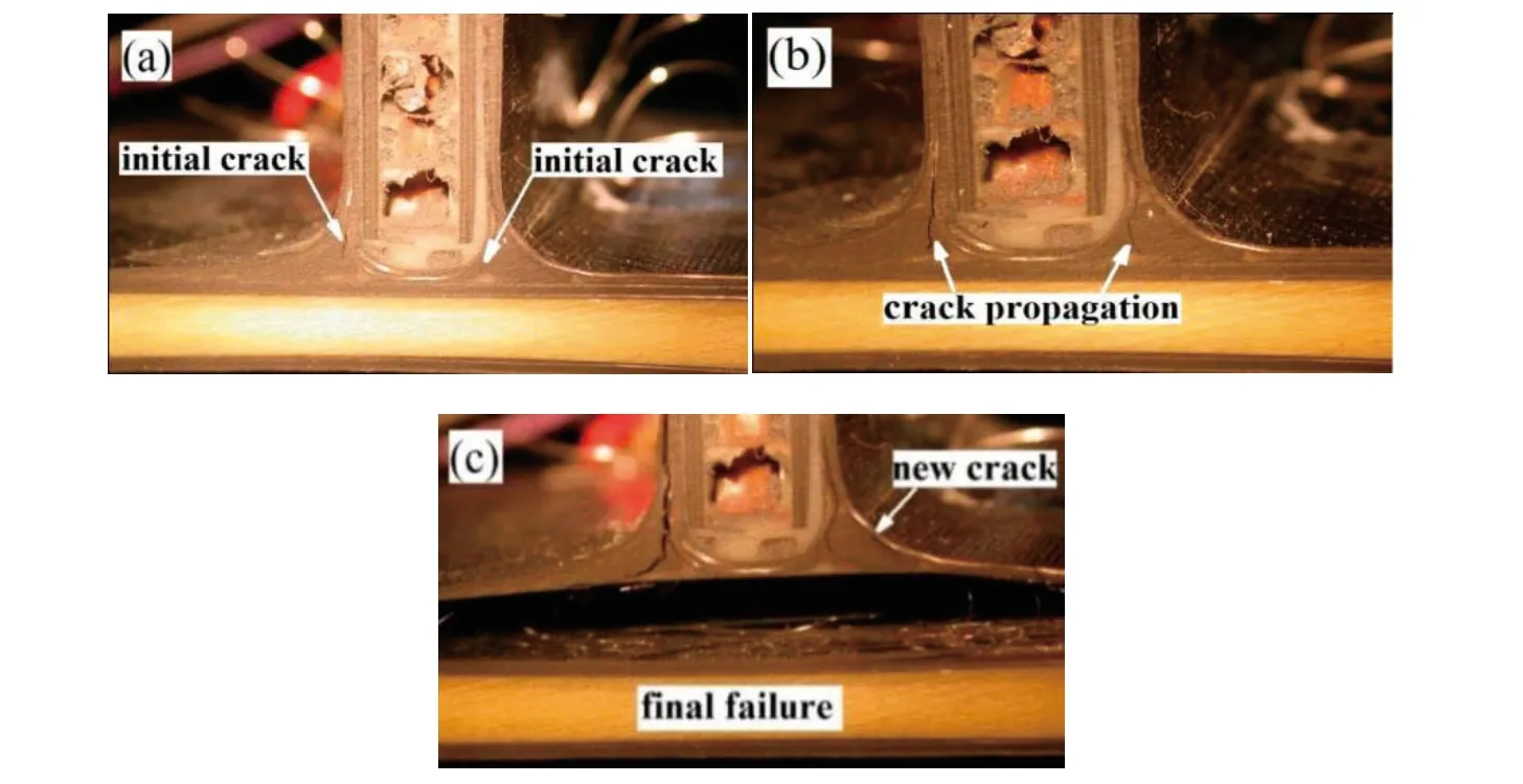
Figure 5: Damage evolution process during the experiment: (a) crack onset; (b) crack growth process; (c) eventually damage morphology

Figure 6: Damage evolution process simulation: (a) schematic of damage evolution process; (b) crack initiation; (c) crack propagation in fillers; (d) crack growth into critical interface above the skin; (e) final failure state
4 Conclusions
This paper proposed a ply-by-ply discretized 2D FEA approach of damage prediction for laminated composite structures, which firstly combined the ply-by-ply 2D FE model technique based on a 2D material model with the integrated CE-XFEM strategy. This approach included a 2D FE modelling technique through ply-by-ply modelling for each composite lamina, and a general crack growth simulating scheme with the integrated XFEM-CE strategy. To realize the ply-by-ply 2D FE modelling for the composite laminates, two 2D material models for calculating the equivalent material properties in the transverse plane for every single ply in the 2D FE model of composite laminates were developed, which were respectively applicable to the problems that satisfied the plane stress condition and plain strain condition. Then a general crack propagation scheme based on the integrated XFEM-CE method was developed, which could simulate the interaction and coupling of matrix cracking and delamination during the damage evolution in composites structures. In the general crack propagation scheme, the cohesive elements adopting the quadratic nominal stress criterion and the B-K fracture criterion were used to model delamination growth. The maximum principal stress criterion and pure mode damage evolution were adopted in the simulation of matrix cracking in composites ply with the XFEM.
The ply-by-ply discretized 2D FEA approach with the integrated XFEM-CE strategy proposed in this paper was applied to a complex out-of-plane composite Pi joint. On consideration of the characteristic of the joint configuration and the loading condition, the material model based on the plain strain assumption was chosen to calculate the equivalent engineer constants for each composite ply in the composite Pi joint. The predicted load-displacement response and damage evolution simulation of the composite Pi joint showed a good agreement with the experimental results. Besides, the 2D FE model had markedly reduced number of nodes and elements compared with the traditional 3D model, and the 2D FEA procedure was completed in 46 minutes. So, the ply-by-ply discretized 2D FEA approach with the integrated XFEM-CE strategy proposed in this paper showed an excellent computational efficiency, which would have a good prospect in engineering applications.
Acknowledgments:This work was supported by the National Natural Science Foundation of China (11772028, 11872131, 11702012, U1864208, 11572058 and 11372020).
 Computer Modeling In Engineering&Sciences2019年7期
- Computer Modeling In Engineering&Sciences的其它文章
- A Hierarchy Distributed-Agents Model for Network Risk Evaluation Based on Deep Learning
- Region-Aware Trace Signal Selection Using Machine Learning Technique for Silicon Validation and Debug
- Blending Basic Shapes By C-Type Splines and Subdivision Scheme
- Equivalence of Ratio and Residual Approaches in the Homotopy Analysis Method and Some Applications in Nonlinear Science and Engineering
- Numerical Validations of the Tangent Linear Model for the Lorenz Equations
- Modelling and Backstepping Motion Control of the Aircraft Skin Inspection Robot
