Time Domain Analysis on Ship Motions in Waves with Translating-Pulsating Source Green Function
SUN Xiao-shuai,YAO Chao-bang,XIONG Ying,YE Qing
(1.China Marine Development and Research Center,Beijing 100000,China;2.School of Naval Architecture and Ocean Engineering,Huazhong University of Science and Technology,Wuhan 430074,China;3.School of Naval Architecture and Ocean Engineering,Naval University of Engineering,Wuhan 430033,China)
Abstract:The seakeeping performance of a ship in waves was investigated in time domain,with the retardation function computed from transforms of frequency hydrodynamic data evaluated based on the Three Dimensional Translating-Pulsating source Green function(3DTP).The motion equations were referenced to both the equilibrium axis system and the body fixed axis system.Comparisons were made among the present time domain method,the frequency domain method and the experiment.The results indicate that it is highly efficient to calculate the retardation function by the frequency to time domain transformation method.The motion responses obtained from equations referenced to the equilibrium axis system indicate shifts when compared with the frequency domain results,especially for the pitch motion,while motion responses obtained from equations referenced to the body fixed axis system indicate satisfactory agreement with both the frequency domain results and experimental results.
Key words:three dimensional translating and pulsating source Green function;seakeeping;time domain;retardation function
0 Introduction
The seakeeping performance of ships in seaway is one of the most significant aspects of ship design and designers have proposed a wide variety of arrangements to reduce ship motions in waves.A lot of efforts have been focused on using both linear and nonlinear potential flow for seakeeping problems.In the early 2 000s,the majority of all seakeeping computations at forward speeds were carried out based on strip theory[1].The use of 3D panel method to study seakeeping problem is becoming more common in recent years,since it overcomes the deficiencies in the strip theory methods[2-3].
The 3D Green function and Rankine singularities are the most popular in the 3D potential theory[4].The Green function method has advantages in that it requires distribution of sin-gularities only on the wetted hull surface,and it satisfies the far field radiation condition automatically.The 3D Translating-Pulsating source Green function(3DTP)which satisfies the classical linearized free surface condition with a forward speed may be more genuine and stricter than the other methods.In contrast,the Rankine source method has the advantage of the flexible choice of free surface conditions.However,the Rankine panel method needs special attention in satisfying the radiation condition when the Brard number τ(τ=uωe/g)is less than 0.25.Besides,more panels will be needed since the free surface should also be discretized.
The frequency domain method provided good solutions for problems of steady-state sinusoidal motions with small amplitudes.However,when it comes to large amplitude motions with strong nonlinear hydrodynamic phenomenon like slamming,the time domain method may give better results.The retardation function that contains all the memory of the fluid response should be included in the equations of motions in time domain[5].It can be solved either by the direct time domain method(DTM)or the frequency to time domain transformation method(FTTM)[6].The DTM means that the initial-boundary value problem in time domain is directly established and the velocity potential is divided into a transient-effect part and a memory-effect part based on the impulse response function.Then each part is solved respectively by utilizing different forms of Green function,such as pulsating source Green function,translatingpulsating source Green function and Rankine source Green function.The FTTM refers that the retardation function is evaluated using a series of hydrodynamic coefficients calculated in frequency domain.Kim et al(2007)[7]and Jiang et al(2015)[8]investigated the coupling effects of ship motions and sloshing with the FTTM.Rajendran et al(2015)[9]applied FTTM to obtain the retardation function and developed a partially nonlinear time domain code based on strip theory to include body nonlinearity in the calculation of radiation and diffraction forces.Ballard et al(2003)[10]compared the results obtained from motion equations referenced to both equilibrium and body fixed axis system.
The present study primarily focuses on the development of a time domain method to investigate the seakeeping behavior of a ship in waves.The retardation functions are computed from transformations of frequency hydrodynamic data evaluated based on the Three Dimensional Translating-Pulsating source Green function(3DTP).The motion equations were referenced to both the equilibrium axis system and the body fixed axis system.Comparisons were made among the present time domain method,the frequency domain method and the experiment.
1 Time domain method for seakeeping investigation
1.1 Coordinate system
Let Oxyz be the Cartesian right-handed coordinate system,with origin O in the plane of the undisturbed free surface Z0=0 with positive z-axis pointing upwards through the center of gravity(COG).The coordinate system Oxyz is fixed with respect to the mean oscillatory position of the vessel which means that it does not oscillate with the ship.The coordinate system Oxyz moves forward with the same speed U of the vessel.In addition,Fig.1 shows a body-fixed coordinate system O′x′y′z′which coincides with the coordinate system Oxyz when the ship does not oscillate.O0X0Y0Z0is an earth-fixed coordinate system with positive Z0-axis pointing upwards.The position of the body-fixed coordinate system O′x′y′z′in the coordinate system Oxyz indicates the vessel's motion responses ηj,where j=1,2,… ,6 refer to surge,sway,heave,roll,pitch and yaw,respectively.In order to avoid any possible confusion due to the different coordinate systems which will be introduced next,the coordinate system Oxyz will be called the seakeeping coordinate system.
Bailey et al(1998)[11]developed a unified mathematical model describing the maneuvering of a ship travelling in a seaway.In his study,the motion equations were referenced to the maneuvering body-fixed coordinate system as shown in Fig.2.The Cartesian right-handed maneuvering body-fixed coordinate system Gxyz with positive z-axis pointing upwards is defined with respect to the ship's center of gravity.The center of gravity is in the origin G of the coordinate system Gxyz in the body lateral symmetry plane with the arbitrary vertical position zg.
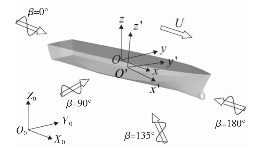
Fig.1 Coordinate systems of seakeeping investigation
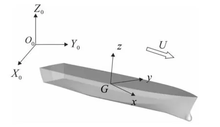
Fig.2 Maneuvering body-fixed coordinate system
By imposing the small disturbances in the form of velocities u,v,w,p,q,r,the ship is disturbed from its equilibrium position.The save level of disturbances is experienced by the maneuvering body-fixed coordinate system Gxyz.Since the seakeeping coordinate system Oxyz is fixed with respect to the mean oscillatory position of the vessel,the relationship between the velocities in the seakeeping coordinate system Oxyz and the maneuvering body-fixed coordinate system Gxyz can be shown as follows[12]:


For the center of gravity,the velocities in respect to the seakeeping coordinate system can be expressed as


where


1.2 Motion equations
According to Cummins(1962)[5]and Ogilvie(1964)[13],the 6-DOF motion equations of a vessel defined in respect to the seakeeping coordinate system Oxyz in time domain can be expressed as

where Mijis the mass matrix,Aijand Bijare the matrices of the added mass and damping coefficients,respectively.∞means that the wave encounter frequency is infinite.Cijis the restoring matrix.Kijare the response impulse functions(the retardation functions).Fiis the wave excitation force and moment.


According to Ogilvie[13],after some manipulations with the Eq.(7)by using the Eqs.(4)-(6),the 6-DOF motion equations of a vessel defined in respect to the maneuvering body-fixed coordinate system Gxyz in time domain can be expressed as


1.3 Retardation functions
The retardation functions Kij(t)defined in respect to the seakeeping coordinate system could be calculated from the added mass and damping coefficient in frequency domain.

The Three Dimensional Translating-Pulsating source Green function(3DTP)which satisfies the classical linearized free surface condition with a forward speed may be more genuine and stricter than other methods such as the pulsating source Green function and Rankine source Green function in the 3D potential theory.Based on the variable substitution and the steepest descent integration method,a fast numerical calculation method can be obtained for the 3DTP[14-15].The added mass Aijand damping coefficient Bijin this paper are all calculated based on the 3DTP.
In an actual numerical calculation of the retardation function,a truncation error is inevitable since the integral of Eqs.(11)and(12)is generally carried out in a finite-frequency range.To minimize this truncation error,a special treatment developed by Kim et al(2007)[7]is applied here.
By considering the inverse transform of the retardation function,it is found that

For a sufficiently large cut-off frequency Ω,the retardation function with a correction of the truncation error can be approximated by using Eq.(13):

where


1.4 Calculation of retardation functions
In Eqs.(11)and(12),the term sinωt and cosωt can be found and may result in oscillation of the integrand.Assuming Dij(ω, t )=[Bij(ω )-Bij(∞ )]cos( ωt),Fig.3 illustrates the D33(ω, t ) of Wigley III at different time.It can be seen that the oscillation of the integrand intensifies with the increase of time.

Fig.3 Typical images of integrand D33(ω, )t
Since the integral of Eqs.(11)and(12)is generally carried out in a finite-frequency range and the integrand indicates an oscillatory property,the direct application of trapezoidal integration would result in significant numerical error.The following steps were carried out to improve degree of accuracy:
(1)Conduct cubic regression of all the damping coefficients evaluated in frequency;
(2)Obtain more damping coefficients by interpolation and we could get B1,B2,…,Bn;
(3)The damping coefficients between Biand Bi+1can be expressed as Bi(ω) =aiω+bi.where

(4)The integration between Biand Bi+1can be solved analytically and the Kij(t)is calculated by

The comparison between the trapezoidal integration and the present method is shown below.The numbers of damping coefficients obtained by interpolation n1 and n2 are 200 and 1 000,respectively.The result of K33obtained by the present method is more stable with the increase of time,while the result calculated by the trapezoidal integration indicates oscillation at t>10 s when n1=200 and at t>140 s when n2=1 000.It implies that the oscillation of the integrand can be reduced when more damping coefficients are used to calculate the retardation function by the trapezoidal integration.However,the oscillation of the integrand does not disappear and will show again in the future.In contrast,the result of the retardation function evaluated by the present method is always convergent by using fewer damping coefficients.
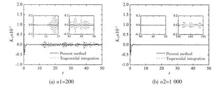
Fig.4 Effect of integral method on retard function
2 Validation of the present method
Numerical calculations were made to evaluate the retardation function and motion responses of Wigley III and S60 by the present method.Comparisons with other researchers'results are shown as follows.The main parameters of Wigley III and S60 are given in Tab.1.

Tab.1 Main parameters of hull models
At present,the heave motions are non-dimensionalized by wave amplitude ζ,while pitch motions are non-dimensionalized by wave slope k0ζ.
The retardation functions of Wigley III at different forward speed are illustrated in Fig.5 and Fig.6,in which‘3DP'means the results are evaluated based on the three dimensional pulsating source Green function.It can be seen that the present results based on 3DP show very good agreement with those calculated by Tang et al(2013)[6]based on 3DP when t>0.5 s,while differences could be found when t<0.5 s for the reason that different cut-off frequency was selected.Minimal discrepancy is observed for K33when comparing the present results based on 3DP with those based on 3DTP,while the discrepancy is much more pronounced for K55.The reason may lie in the differences between the pitch-pitch damping coefficients evaluated from different kind of Green functions.Since the 3DTP directly takes the speed effect into account,the results based on 3DTP seem to be more reasonable.
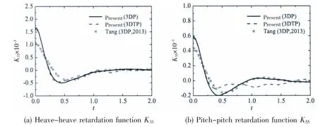
Fig.5 Comparison of retard function of Wigley III at Fn=0.2

Fig.6 Comparison of retard function of Wigley III at Fn=0.3
Fig.7 and Fig.8 show the motion transfer functions of Wigley III at different advancing speed.‘Exp'means the results obtained by experiment carried out by DUT[16]and ‘FD'means the results calculated based on 3DTP in frequency domain.‘TD-Oxyz'means the results calculated in respect to the seakeeping coordinate system in time domain,while‘TD-Gxyz'means the results calculated in respect to the maneuvering body-fixed coordinate system in time domain.Satisfactory agreement is observed between the results evaluated based on 3DTP in frequency domain and those obtained from experiment.
Comparisons of results between ‘FD'and ‘TD-Oxyz'depict differences,especially for the pitch transfer functions.Good agreement is achieved for heave transfer functions at Fn=0.2,while obvious difference could be found in resonant zone at Fn=0.3.The discrepancy of the results between ‘FD'and ‘TD-Oxyz'is more pronounced with the increasing advancing speed.
The comparison of motion transfer functions between‘TD-Gxyz'and experiment shows very good agreement at different forward speed,so it implies that the motion equations in time domain should be solved in respect to the body-fixed coordinate system to obtain accurate results.
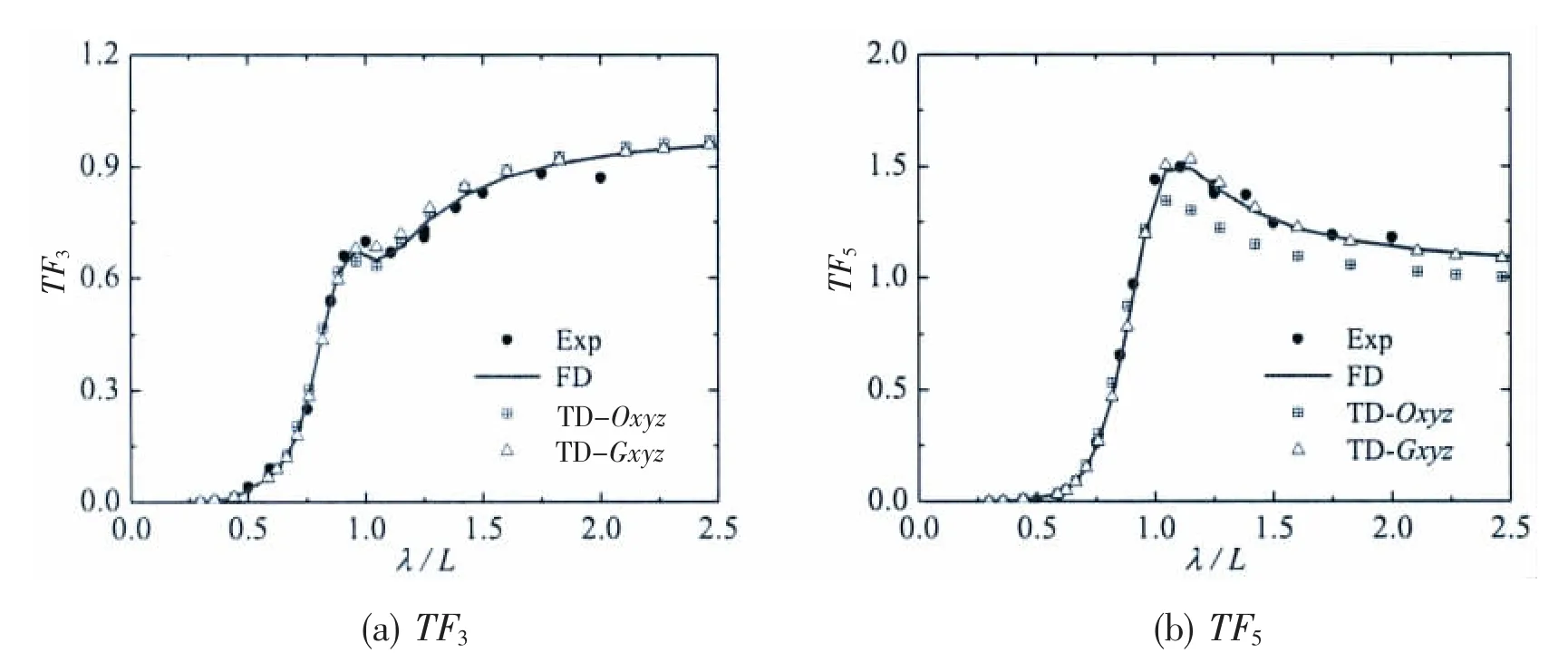
Fig.7 Comparison of the transfer function of Wigley III at Fn=0.2
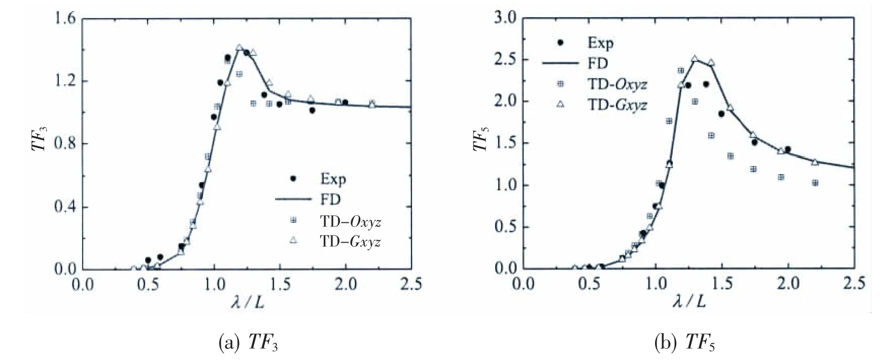
Fig.8 Comparison of the transfer function of Wigley III at Fn=0.3
Fig.9 and Fig.10 indicate the retardation functions of S60 with respect to the seakeeping coordinate system and the maneuvering body-fixed coordinate system,respectively.The present results agree well with those obtained by Ballard et al(2003)[10],which validates the present numerical method.The retardation functions see a drop trend at beginning and trend to zero when t>2 s,which implies that the memory effect disappear.
The motion transfer functions of S60 at different advancing speed are shown in Fig.11.The results presented by Ballard et al(2003)[10]are based on the 3DP.It can be seen that the results in frequency domain based on 3DP and those based on 3DTP indicate minimal difference for the reason that the vessel advances with moderate forward speed.
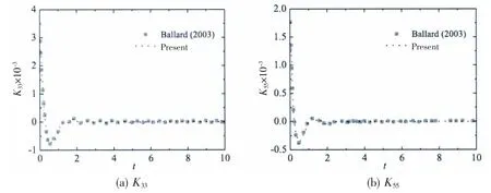
Fig.9 Comparison of the retardation function of S60 referenced to the seakeeping axis system
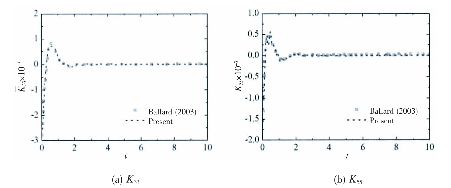
Fig.10 Comparison of the retardation function of S60 referenced to the body-fixed axis system
The heave transfer functions calculated by the present method with respect to the seakeeping coordinate system illustrate differences in the resonant zone when compared with those obtained by Ballard et al(2003)[10],while the pitch transfer functions indicate good agreement.A shift could be found in both the present results and Ballard's results when comparing the results in frequency domain and time domain with respect to the seakeeping coordinate system.
The present results and Ballard's results show that good agreement is observed when comparing the results in frequency domain and those in time domain with respect to the maneuvering body-fixed coordinate system.It illustrates that accurate results can be obtained by solving motion equations referenced to the body-fixed axis system.
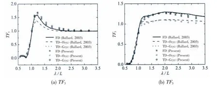
Fig.11 Comparison of the transfer functions of S60 at Fn=0.2
Ballard et al(2003)[10]explained the reason for the differences found between the results with respect to the seakeeping equilibrium axis system and maneuvering body-fixed axis system.He found that some equilibrium axis added mass coefficients,such as A55,tend to infinitely high values at low frequency when the forward speed is not zero,which results in the difficulty to accurately calculate the retardation functions that can adequately represent such trends.However,hydrodynamic coefficients referenced to the maneuvering body-fixed axis system do not display similar trends.
The above numerical simulations on Wigley III and S60 validated the time domain method for seakeeping investigation on monohulls.It can be found that motion equations referenced to the body-fixed axis system in time domain result in more accurate motion responses.
3 Conclusions
In the present work,the ship motions in regular waves were investigated in time domain numerically,with the retardation function computed from transforms of frequency hydrodynamic data evaluated based on the Three Dimensional Translating-Pulsating source Green function(3DTP).A new integral method was established to calculate the retardation functions that contain memory effect.The retardation functions can be calculated from hydrodynamic coefficients referenced to either the seakeeping equilibrium axis system or the maneuvering body-fixed axis system.The results indicate that it is highly efficient to calculate the retardation function by the frequency to time domain transformation method.
The motion responses obtained by solving the motion equations referenced to the bodyfixed axis system show minimal difference compared with the frequency domain results,while the motion responses obtained by solving the motion equations referenced to the equilibrium axis system indicate shifts compared with the frequency domain results,especially for the pitch motion.
The present study in time domain can then be further extended to investigate nonlinear hydrodynamic forces,such as the nonlinear wave excitation forces and nonlinear restoring forces.
- 船舶力学的其它文章
- A Multiple Validation Based Methodology of Confidence Level Assessment for Virtual Test of Ship Hydrodynamics
- Research on the Mechanism and Characteristic of Added Resistance of Moonpool with Recess
- LQR Control of a Three Dimensional Underwater Glider
- A New Scheme for Vortex Sheet Diffusion in Fast Vortex Methods
- Research on the Design and Parameter Influence Law of A High-Static-Low-Dynamic Stiffness Vibration Isolator Using for Marine Equipment
- Experimental Investigation on Dynamic Behavior of Porous Material Sandwich Plates for Lightweight Ship

