Performance characterization of Bi2O3/Al nanoenergetics blasted micro-forming system
Viny Kumr Ptel,Rishi Knt ,Anu choudhry ,Mdhusudn Pinuly ,Shntnu Bhttchry
a Department of Mechanical Engineering,Govind Ballabh Pant Institute of Engineering&Technology Pauri-Garhwal,246194,Uttarakhand,India
b Department of Mechanical Engineering,Indian Institute of Technology Kanpur,208016,Uttar Pradesh,India
Keywords:Microforming Aluminum Foil Bi2O3 Nanoenergetic Tunability Process parameters
A B S T R A C T This paper reports a novel micro-blast driven manufacturing process for micro-forming of Aluminum foils.The micro-blast is realized by using a nanoenergetic material system comprising of Bi2O3 microrods and aluminum particles.There is an enhanced need of forming of thin aluminum foil structures in small regions from point of view of drug packaging etc.The process developed caters to this need by using a single shot forming process using a micro-blast source.The micro-blast that is generated from an energetic composite system is made highly tunable by modulating the peak pressure generated through the blasting process and their impact in micro-forming of thin aluminum foils is observed through parametric studies.The engineering challenge involved in these experiments is to tune the blast pressure properties in order to address the forming of thin metal sheets with limiting boundary values as defined by the failure criteria.A variety of characterization techniques related to a thorough analysis of the synthesized material viz.X-ray diffraction(XRD),Scanning Electron Microscopy(SEM)etc.are used to tune the functional properties like gauge blast pressure etc.of material system.We have found a material system that can generate a maximum peak pressure of 73.8 MPa with pressurization rate of 2460 GPa s-1 and that is able to accomplish micro-forming on thin metal foils(around 0.3 mm thickness).Experimental investigations demonstrate that tunabilty aspect of the energetic composites when exercised can enable variant processes such as embossing,coining,drilling etc.which may be of significant utility to drug packaging industries.A proper mathematical modeling of the forming process and critical process parameters therein have also been detailed.
1.Introduction
In recent years,the nano-energetic materials have emerged as advanced functional materials with properties such as ultra-fast energy release and excellent pressure-time characteristics resulting in pulse power which can be deployed in many civilian and defence applications[3].Nanoenergetic materials present a new class of meta-stable intermolecular composites which comprise of a nanoscale metal fuel(mostly aluminum nanoparticles)and transition metal oxides like CuO[1],Bi2O3[2,3],MoO3[4],Fe2O3[5],I2O5[6],Co3O4[7]etc.These materials produce a rapid releaseof heat and pressure by self-propagating combustion reaction.The density of the released energy and the overall combustion kinetics of such systems can be tailor made by altering the chemical composition,size and scale(microscale/nanoscale/atomic scale),morphology and the level of assembly among these composites.The fuel and oxidizer particles in the nano-scale possess enhanced surface area and reduced inter-diffusion distance which leads to elevated rate of exothermic reactions,higher ignition sensitivity and enhanced energy release rate with minimum heat dissipation[8,9].The impulse caused by these energetic materials finds useful applications in microthrusters[10],safe arm devices[11],and drug/gene delivery micro-devices[12].In this article,we have investigated the impulse of energetic material systems for metal(aluminum foil in our case)forming applications.Such microformed products find wide ranging applications in many areas like packaging of pills in pharmaceutical products,small components for aerospace and automotive industries etc.The impulse forming provides a high throughput alternative in some applications in comparison to other variants like incremental forming[13-15],micro deep drawing[16],Laser assisted bending[17]etc.
In our investigations,the bismuth oxide-nano-aluminum system was selected because of its superior properties like high peak pressure and steeper pressure rise rates[2,3].A possible explanation for the high pressure rise during the combustion of Al/Bi2O3energetic composites is the lower boiling temperature of bismuth(1560°C)than the maximum reaction temperature(2000°C)which causes bismuth to evaporate and increase the overall gas pressure[3],[18].The bismuth trioxide composite is considered as a highly reactive energetic material system and it able to generate a rapid and high pressure discharge with a high burn velocity of about 2500 m/s[18].
2.Materials and methods
2.1.Materials and equipments
All materials used are in their as obtained formwithout applying any purification steps.Aluminum nanoparticles(average particle size of~80 nm)were procured from M/s Neo Ecosystems.The Ultrasonic mixer(capacity 2.5 L)was taken from M/s Citizen Scales and the vibra cell from M/s Sonics&Material,Inc.The nichrome wire of 0.05 mm diameter was used as a source of ignition using a DC power supply.Aluminum foil of 0.3 mm thickness(AL000635 and CAS no.7429-90-5)purchased from M/s Sigma-Aldrich.
2.2.Synthesis of Bi2O3 micro-rods
The Bi2O3micro-rods were fabricated by a surfactant free sonochemical process as used by Soodet.al.in 2015[19]for the formation and growth of Bi2O3micro-rods,0.1 M bismuth nitrate solution was prepared by adding 4.8 g Bismuth(III)nitratepentahydrate(BiNO3)3.5H2O in ultrasonic bath of 100 ml of deionized water.The precursor solution was ultrasonically treated for 45 min to get a white suspension(pH of the solution about 5.5),followed by addition of 10 M KOH solution and followed by the same ultrasonic treatment(duration=1 h)to achieve the final pH 8 of the prepared solution.The resultant solution was then ultrasonically processed for 8 h to obtain a yellow precipitate which was collected through centrifugation and subsequently washed and cleaned with ethanol and deionised water.The post washed sample was further heated at 60°C to get a dry powder which was finally calcined at 450°C for 2 h to obtain the Bi2O3micro-rods.
2.3.Preparation of energetic composites
The energetic composites of the desired quantity were prepared by ultrasonic mixing of accurately weighted Bi2O3micro-rods with the aluminum nanoparticles in weight ratio of 4.3:1 in 2-propanol(30 ml)solution using the Sonics vibra-cell ultrasonic processor.The pulse duration was maintained at 10 s to avoid any thermal gradients within the solution which the ultra-sonication was carried out.After ultra-sonication for about 10-15 min,the slurry was further transferred into a glass petri-dish and dried at 95°C in the oven till complete evaporation of 2-propanol took place.
2.4.Characterization of the material
The morphology and composition of the Bi2O3microrods was determined by Scanning Electron Microscope(SEM)and X-ray diffraction(XRD).A fully instrumented pressure monitoring cell as shown in Fig.1 was assembled to determine the dynamic pressuretime characteristics of microrods-Bi2O3/n Al composites.
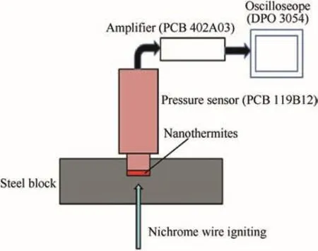
Fig.1.Schematic of testing set up.
The pressurization rate of the energetic composite was estimated by measuring the pressure generated during the combustion of 20 mg,30 mg and 40 mg of microrods-Bi2O3/n Al composites in a constant volume pressure cell of diameter 6.5 mm and the depth of 5 mm(Fig.1).One end of the metallic block housing the pressure cell was closed with a pressure sensor and the test material in powder form was filled inside the closed chamber.The pressure sensor(PCB 119B12)having measurement range of 0-827 MPa was mounted and screwed over the metallic block with internal threads.The source of ignition was a nichrome wire of diameter 0.05 mm which was connected to a DC power source from the opposite end.In order to get the low impedance voltage output,the output of the charge from the monitored pressure signal was applied to an amplifier(PCB 402A03).The signal data from the amplifier(PCB 402A03)was recorded by the digital oscilloscope(DPO 3054)and compared with the calibration curve of the pressure sensor to find out the dynamic pressure-time data.
2.5.Description of the blast pressure generator to carry out the micro-forming operations
The blast-pressure generator consists of a combustion chamber of diameter 6.25 mm and a depth of 5 mm,wherein the energetic composite was ignited by nichrome-wire connected with DC-voltage supply through a fine passage from its bottom side as shown in Fig.2(a).The aluminum foil was placed by covering the combustion chamber and tightened by the die-plate.The die plate consisted of a hemi-spherical cavity for facilitating of forming operation(Fig.2(a)).Fig.2(b)is the schematic diagram of Bi2O3/Al nanoenergetics blasted micro-forming of aluminum foil.
3.Results and discussion
3.1.Theoretical analysis
The analysis of the results that are obtained are explained in terms of a mathematical model as suggested by Nurick et al.,in 1989[23].Also,a simulation tool ABAQUS is utilized for predicting the foil deformation(details provided later)through which the blast pressure wave effect on thin aluminum foils are predicted through simulations.In the present case,aluminum foil of 0.3 mm thickness is kept between a set of upper and lower die and a blast wave is propagated from upper die to lower die via ignition of the nanoenergetic material.The lower die consists of a circular cavity of 6 mm diameter.The foil starts deforming (plastically)on application of blast pressure which is order of 40-70 MPa.

Fig.2.(a)Blast pressure generator for micro-forming;(b)Schematic diagram of Bi2O3/Al nanoenergetics blasted micro-forming of aluminum foils.
Recently Yuen et al.[25]carried out an extensive review on deformation of thin plates which are subjected to impulse loading in 2016.Yuen et al.[25]suggested that one of the most successful model to predict thin plate deformation subjected to impulse loading,is the model described by Hudson in 1951[24]and Nurick et al.,in 1989[23].The time scales that are recorded in both these suggested models are in the 100s of micro seconds range which is the time scale the deformation event.As in all our experiments a blast of round about a few 100s of microseconds duration is the main cause of deformation,therefore,in our opinion the same concept of impulse loading to mathematically ascertain the behaviour of our foils can be utilized.Nurick et al.[23]suggested an empirical relationship in non-dimensional form for permanent deflection-thickness ratio(without failure of thin plate by tensile tearing or shear failure)as per the following equations in 1989

Where φcis non-dimensional number,R(6 mm)is exposed radius to blast,t(0.3 mm)is thickness of aluminum foil,σ(100 MPa)is yield stress of aluminum foil,ρ(2700 kg/m3)is density of aluminum foil,I is input impulse by blast wave,

This model is based on assumption of uniform loading on circular aluminum foil.In case of the experiments,the blast pressure data have already recorded and plotted the same in Fig.3(a)~(c).The total impulse(I)has been calculated from this data for the aluminum-Bi2O3system(which is plotted in Fig.3(b))to be 2.03 N-s for peak pressure of 60 MPa.The impulse is simply the pressure/time/area product.
The maximum deflection(δ)as suggested in the Nurick's non dimensional model is calculated by solving equations(1)and(2)which is obtained as 0.465 mm.The actual deformation obtained experimentally is in the range 0.7-1.28 mm for different weights of the charge that is used(refer Table 1).The slight disparity in theoretically predicting the deformation comes from the fact that the actual deformation in the case of aluminum foils in experiments is obtained under a finite clamping force of 104N whereas in the model as suggested by Nurick the boundary conditions are utilizing completely fixed boundaries with peripheral clamping.

Fig.3.(a)~(c)Image showing the pressure time characteristics for 20 mg,30 mg and 40 mg of energetic composite premixed at their optimum equivalence ratios.

Table 1 Data of the deformed geometry of the aluminium foil of thickness 0.3 mm.
For a better picture of the deformation modelling we also performed finite element based simulations using ABAQUS tool which predicted the experimentally obtained data reasonably well.For the assume that the actual blast wave is nonlinear and exponentially decaying in nature(Fig.4).There exist several empirical equations to describe its behaviour and all these equations are strictly based on observations made by various researches[20-22].The original Friedlander's equation is independent of atmospheric pressure[21].
However,modified Friedlander's equation(with atmospheric pressure,P0)is commonly used to model the blast wave as following equations

Where the parameter b denotes the decay of the pressure-time curve and taken as 1,Psis peak positive over pressure,P0is the ambient air pressure,t is the time of arrival,t*is the delay time.
3.2.Numerical analysis of aluminum foil deformation on application of pressure pulse
The pressure time characteristics as obtained in Fig.4 are further imported into ABAQUS ver 6.14.The drawability of aluminum foil is further explored under blast pressure.Due to symmetricity of the problem statement,only half section of actual model is taken into consideration.For simplicity and computation time saving,2D model with axial-symmetry is generated for analysis.Since,blast time is for few micro second hence flow stress dependency on temperature is neglected.
The complete geometry including blank(30 mm,thickness 0.3 mm),die(pocket size of 6.5 mm(in 2D a half circle of 6.5 mm diameter)and 0.15 mm corner radius)and blank holder(60 mm×40 mmwith pocket size of 6.5 mm and 0.1 mm die corner radius)is realized in ABAQUS environment and assembled using the assembly tool.Different parts of the geometry are meshed separately with 0.08 mm global elemental size to control the contacts during process simulation.
The material properties of aluminum such as elasticity and plasticity are defined as per following parameter given in Table 2.Table 3 summarizes applied boundary conditions to the model shown in Fig.5.
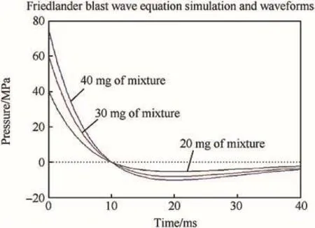
Fig.4.Image of the theoretical study of pressure with time for the varying amount of the mixture.
The material(aluminum)gets deformed by the blast pressure due to ignition of the nanoenergetic material.The deformation behaviour of this material is different for different applied loads which can be physically realized by customizing the nanoenergetic material for different peak pressure values.The deformation profile as obtained through ABAQUS with a load of 39 MPa is illustrated in Fig.6(a).The maximum depth which can be achieved under this load is 0.79 mm which is nearly similar to experimental value 0.70 mm given in Table 1 corresponding to 39 MPa.The FEM model therefore shows a better estimate of the experimentally obtained values as it incorporates a finite clamping force on the samples.
Fig.6(b)shows the deformation profile of aluminum foil under 60.8 MPa blast pressure where the maximum depth 1.3 mm is achieved in simulation while it is actually obtained experimentally as 1.18 mm with a similar pressure.
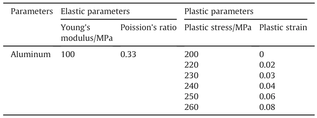
Table 2 Material properties of aluminum.

Table 3 Boundary conditions.
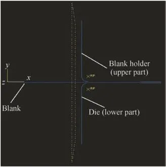
Fig.5.2D view of model used for simulation.
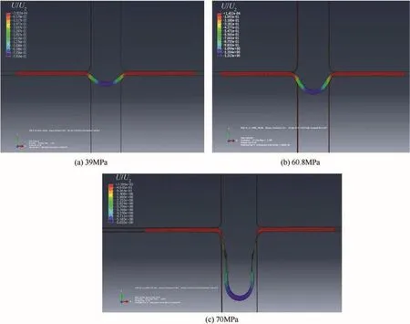
Fig.6.Deformation profile of aluminum foil at pressure(a)39 MPa(b)60.8 MPa(c)70 MPa.

Fig.7.FESEM Image of(a)Bi2O3 microrods(b)Bi2O3/n Al nanothermite composite.
The aluminum foil under 70 MPa blast pressure has been seen to fracture from the die side(Fig.6(c)).This is because of material deformation crosses the plastic strain limit offered by material(aluminum)under this pressure.A small circular shape of material is getting stretched(plastically deformed)in form of excessive distortion ofmeshed elementunderthis load which can be seen in Fig.6(c).
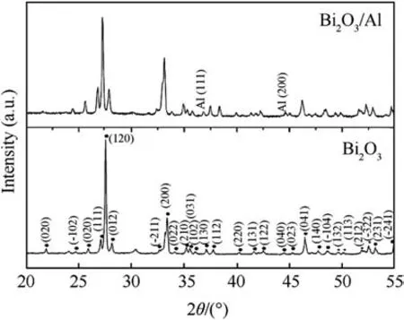
Fig.8.XRD images of Bi2O3 micro-rods and Bi2O3-n Al thermite composite.

Table 4 Peak pressure obtained at varying amount of the mixture.
3.3.SEM and XRD results of Bi2O3/n-Al energetic material
Fig.7(a)shows the SEM images of bismuth oxide microrods having about square-shaped cross-sectional area of edge-length about 0.5-2μm and Fig.7(b)shows the ultrasonically mixed composite of bismuth oxide micro-rods and aluminum nanoparticle.The XRD data of bismuth oxide microrods and its nanothermite composite is plotted in Fig.8.It is clear from the observed spectra that the bismuth oxide sample is highly pure and possesses monoclinic structure.The observed XRD pattern is well matched with the JCPDS card no:71-2274.The spherical particles in the micrograph in part(b)represent aluminum nanoparticles.The commercially available grades of such particles have the wide particle size distribution which may result in incomplete assembly of the Al-nanoparticle around the microrods of Bismuth oxide.However,as our pressure requirements are lesser owing to the rupturing tendency of the aluminum foil at a high peak pressure therefore it is pertinent to operate at the obtained morphology to cause a lower peak pressure rise.
3.4.Pressure characterization from ignition experiments of the bismuth oxide nano aluminum composites
The micro-blast is carried out by packaging the material and igniting using the Nichrome wire and the pressure data is acquired through the pressure sensor connected to a high acquisition rate oscilloscope.An evaluation of pressure is carried out corresponding to different weight of the energetic composite pre-mixed at their optimized equivalence ratio.Peak pressures ranging from 73.8 MPa to 39 MPa are obtained through acquired data as plotted in Fig.3(a)-(c).Table 4 further summarizes the peak pressure and the pressurization rates as a function of weight of the composites.Bismuth oxide nano aluminum composites are generally found to burn with gasification and generally result in a high pressurization rate 2.46 MPaμs-1and peak pressure of 73.8 MPa.
3.5.Deformation behaviour of aluminum foil

Fig.9.Image of deformation in the aluminum foil of 0.3 mm thickness.
As the blast energy is coupled through the generator into the aluminum foil of thickness 0.3 mm the pressure energy deforms the aluminum foil materials as represented in Fig.9 below.The parts(a)~(c)represent the tensile side of the deformed crosssection while the parts(d)~(f)show the pressure incident side corresponding to peak pressures of 39,60.9 and 73.8 MPa respectively generated inside the pressure generator.We hypothesize that there some dissipation of the energy of the pressure wave as it travels within the generator tube from ignition box to the aluminum foil.A rupture failure of the sheet is observed is case of pressure 73.8 MPa.Since parameters like blank holding force,die corner radius and friction affect the performance of foil deformation by affecting limiting draw ratio of the drawn part.These parameters are optimized to blank holding force(300 MPa)and die radius(0.15 mm)to have successful deformation without tearing of aluminum foil.The limiting draw ratio for successful deformation without rupture is found to 2.4 at these parameters.

Fig.10.Geometry of deformed profile of aluminum foil for 20 mg nanoenergetic material case.
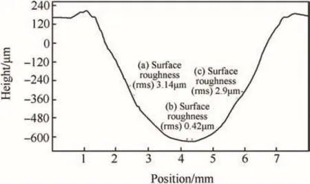
Fig.11.Cross sectional profile of drawn part with surface roughness as different points.
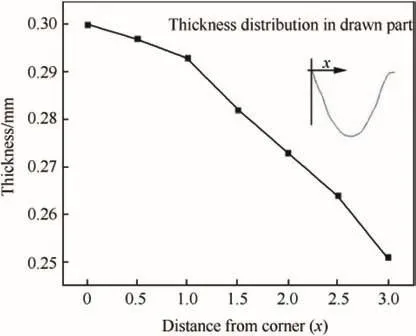
Fig.12.Thickness variation in wall of drawn cup from corner to center.
The dimensions of the deformed zone are measured through the software from the optical micrographs.For an instance,the deformed shape of 0.70 mm height(using 20 mg nanoenergetic material)is considered to measure surface integrity(Fig.10).3D surface profilometry(Nanomap-D)is utilized to measure drawn cup height(Fig.10)and surface integrity(Fig.11).The surface roughness is measured at three different points(Fig.11)which are 3.14μm,0.42μm and 2.9μm.The overall surface roughness is 3.52μm of deformed part.The thickness variation in part is shown in Fig.12 which reveals that min.thickness(0.251 mm)exist at centre of formed part.Table 1 shown below illustrates the dimensions of the deformed portion of the foil including depth of deformed zone,the radius of the deformation zone and the volume.
4.Conclusions
In conclusion,the paper shows a new microforming process of thin foils through micro-blasts with tuned peak pressure and pressurization rates.The tunable blast is achieved by deploying a nanoeneregtic system made up of bismuth oxide and nanoaluminum.The process is validated through both theoretical modelling and simulations.The technique is well suited for a vast majority of metal forming processes like micro-drawing,embossing,tearing,drilling/punching through different levels of peak pressures and pressurization rate provided by the sensitive nanoenergetic composites.
Acknowledgements
The authors acknowledge the financial support provided by Boeing India to Indian Institute of Technology Kanpur,India and TEQIP funding from Government of India provided to G.B.Pant Institute of Engineering&Technology Pauri-Garhwal India.
- Defence Technology的其它文章
- Fluorine-containing oxidizers for metal fuels in energetic formulations
- On the formation of Basu's Type III(peeled orange)gunshot residues
- Interaction of TATB with Cu and Cu+1.A DFT study
- Control of exterior ballistic properties of spin-stabilized bullet by optimizing internal mass distribution
- Crystal lattice free volume and thermal decomposition of nitramines
- Tribological and vibrational characteristics of AISI 316L tested at elevated temperature and 600 Torr vacuum

