Numerical study on influence of structural vibration on cavitating flow around axisymmetric slender body *
Jing-zhu Wang (王静竹), Te-zhuan Du (杜特专), Yi-wei Wang (王一伟),Cheng-guang Huang (黄晨光)
1. Key Laboratory for Mechanics in Fluid Solid Coupling Systems, Institute of Mechanics, Chinese Academy of Sciences, Beijing 100190, China
2. School of Engineering Science, University of Chinese Academy of Sciences, Beijing 100049, China
Abstract: The unsteady behaviors of cloud cavitating flow would lead to structural vibration and deformation that conversely affect its development. The present paper aims to preliminarily discuss the influences of structural vibration on the development of the cavitating flow. Simulations of a slender body are carried out under different vibration amplitudes and frequencies. The results show that the structural vibration causes alternate variation of local attack angle at the head of the body, and thus changes the development of cavitation and re-entrant jet. On the downstream side, the length and thickness of the cavity are larger than that on the upstream side due to larger area of negative pressure. For a large vibration amplitude, alternate variations of the local attack angle change the adverse pressure gradient at the closure of the cavity, and then affect the development of the re-entrant jet, so that the phenomena of local shedding of the cavitation happen, compared with global shedding in the case of no structural vibration. For a frequency larger than 0.05, transverse speed of the vibration is suggested to be a dominant factor in controlling the behavior of the cavitating flow besides the local attack angle, since it causes local cavitating phenomena.
Key words: Structural vibration amplitude and frequency, attack angle, local shedding of cavitation, transverse vibration speed, local cavitating
It is always difficult and challenging to clarify cavitating phenomena for a problem of high-speed fluid solid coupling. First of all, cavitating flow containing liquid, vapor, and air is related to multiple phases and interfaces, comparing with a common fluid-solid coupling such as aeroelasticity. Furthermore, it is required to solve[1-2]the problems of gasliquid boundaries besides gas-solid and liquid-solid interactions. Secondly, the unsteady behavior of the cavitation would cause changes in temporal and spatial loads for the structure[3-4]. In particular, highpressure pulses generated by collapse take main responsible for instantaneous structural vibration. In the meantime, the deformation of the structure also influences the development of the cavitating flow[5].
For the problems of the fluid-solid coupling containing cavitating, most of the present studies focus on the investigation of underwater composite propellers and high-speed vehicles[6-10]. Zhang et al.[6]investigate the deformation characteristic of a composite hydrofoil via numerical simulations. Young[7]analyzed the coupling effect of turbine blades with and without cavitating condition using the boundary element method. Ma[9]studied the behavior of the structure when the projectile was leaving the launch tube.Wang[10]investigated the influence of a two-dimensional movement and structure vibration on hydrodynamics during underwater launch process, by using Fluent. In the above-mentioned studies, the hydrodynamics and vehicle behavior were investi- gated.However, the coupling effects of structural vibration and cavitating flow have not yet been analyzed deeply owing to the complexity of the problem.
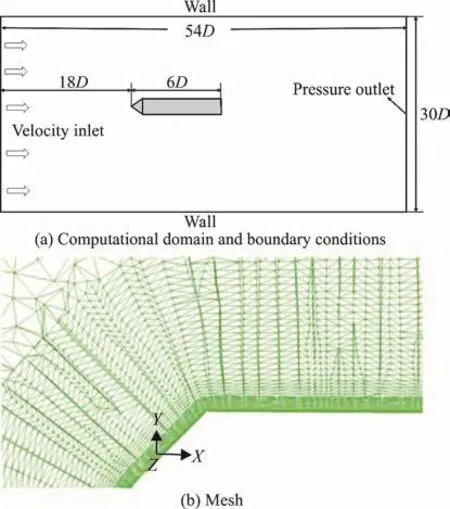
The present study reports on a qualitative investigation about the influence of structural vibration on cavitating flow around an axisymmetric slender body with a blunt cone head of 90° under different amplitudes and frequencies. The CFD model setup is shown in Fig. 1, the wall+y is of the order (1)O . The length of the axisymmetric slender body is six times larger than its diameter D. The diameter of the cylinder is D =37.5 mm , the free-stream velocity is V =18 m/s and the ambient pressure is 101 325 Pa.The corresponding cavitation number and Reynolds number are σ = 0.611 and R e = 6.75× 1 05, respectively. The projectile’s vibration is thought to be a first-order bending vibration with a frequencysf.The dimensionless frequencyof the structural vibration is obtained by defining inherent shedding frequency of the cavitationin this study). The dimensionless amplitude is /A D. A is the maximum displacement of the leading point of body.A hybrid model is applied consisting of a full cavitation model[11], a multiphase flow model to solve three-phase flow problems containing liquid, water vapor, and gas in the simulation. The set of governing equations of the hybrid model comprises the conservative form of the Reynolds-averaged Navier-Stokes equations. A modified RNG -kε model is adopted to better simulate the movement of the re-entrant jet[12]. In addition, the dynamic mesh technique is used to treat the problems of moving boundary. The numerical model was validated in the former work[13].

Fig. 1 (Color online) CFD model setup
Figure 2 shows the behavior of the cavitatin g flow around the projectile induced by the structural vibration when A/ D = 0.10,. The cavity is represented by the iso-surface of vapor fraction with the value of 0.5. In the figure, the head of the body is moving downward at =1mst , and the displacement reaches the maximum at =2 mst . During this process, the upper face and lower face of the body are defined as upstream and downstream side, respectively. According to the characteristic of the flow over a body, the area of negative pressure is larger on the downstream side than the upstream side. Consequently, the cavity length at the lower face increases faster. As shown in Fig. 2(d), it is clearly seen that the length and thickness of the cavity are larger at the lower face when the body head return to the equilibrium position. After that, the head moves upward so that the positions of the upstream and downstream sides are exchanged. From the figure, it is found that the cavity length at the upper face increases gradually and eventually exceeds that at the lower face. In the meantime, the local cavitation shedding occurs from t = 6 ms . It is thought that this phenomenon is related to the development of the re-entrant jet.

Fig. 2 (Color online) Behaviors of cavitating flow around projectileinducedbystructurevibration(A/ D = 0.10,fs / f 0 =1)
Therefore, the behavior of the re-entrant jet is also investigated, as shown in Fig. 3. At =4 mst , the re-entrant jet indicated by the arrow almost reaches flow-separating point at the upper face. Next, the area of negative pressure on this side increases due to the downward movement of the head, so that the adverse pressure gradient decreases at the closure of the cavity.As a result, it delays the cavitation shedding and promotes the increase of the cavity length. On the other hand, at the lower surface, the decrease of the negative pressure area enhances the adverse pressure gradient and results in local cavitation shedding, as shown in Fig. 3(b). Compared with global shedding of the cavitation occurring without structural vibration,the local shedding is thought to reduce the amplitude of hydrodynamic fluctuation.

Fig. 3 (Color online) Development of re-entrant jets induced by structural vibration (A/ D = 0.10, fs / f 0 =1)
The influence of vibration amplitude on the development of the cavitating flow is investigated.Figure 4 shows the variations of the cavity lengths at the upper surface (a) and lower surface (b) under the amplitudes of 0.02, 0.05 and 0.10. The dimensionless frequency was 1. In the case of rigid body, the cavity lengths at the upper and lower surfaces are almost the same, as indicated by solid squares. For A/ D = 0.02,the development of the cavitating flow including the generation and shedding of the cavitation keeps consistent with that obtained at / =0A D , despite slight differences of the cavitation length between the upper and lower surfaces. Hence, small amplitude of 0.02 hardly changes the behavior of the cavitating flow. For a larger amplitude, / =A D 0.05 or 0.10, the overall collapses of the cavity are induced at the positions where the lengths reach 0, as shown by the arrows. In these cases, the variations in the cavity lengths are different compared with / =0A D . The amplitudes of the vibration, i.e., the attack angles at the head of the body are responsible for generating the differences[14]. According to the first-order bending vibration, the attack angle increases with the amplitude of the structure vibration. It can be seen that with the increase of the attack angles, the cavity lengthon the downstream side becomes much larger, while opposite results occur on the upstream side. For a larger vibration amplitude,alternate variation in the local attack angle leads to non-synchronous development of the re-entrant jets between the upper and lower surfaces.

Fig. 4 (Color online) Behaviors of cavitating flows under different vibration amplitudes at fs / f 0=1
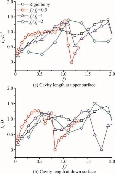
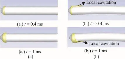
Next, the influence of vibration frequency on the behavior of the cavitating flow is analyzed. Figure 5 shows the variations of the cavity length at the upper surface (a) and lower surface (b) at1 and 2 when A/ D = 0.10. For the frequencies of 0.5 and 1,the behaviors of the cavitating flow are similar. Owing to the structural vibration, there are some differences occurring between the upper and lower faces as well,such as the time of the cavitation shedding. These results suggest that the vibration frequency contribute mainly to changing the behavior of the cavitating flow,i.e., the local attack angle plays an important role in these cases. On the other hand, the result obtained ats not similar to other curves. The reason is that the transverse speed of the vibration could be a main factor beside the attack angle. According to the calculation conditions, the inlet flow velocity was 18 m/s and the peak transverse speed at the head of the body was 1.2 m/s. As shown in Fig. 6, Compared with the behaviors of the cavita- ting flow without structural vibration, the transverse speed leads to the local cavitating phenomena, and then changes the variation of the cavity length.

Fig. 5 (Color online) Behaviors of cavitating flows under different vibration frequencies (A/ D =0.10)

Fig. 6 (Color online) Comparisons of cavity lengths without structural vibration (a) and with vibration condition of= 0.10, fs / f 0 =2 (b)
In conclusion, we present investigations on the influence of the amplitude and frequency of the structural vibration on the behavior of the cavitating flow for a slender body. The structural vibration causes the alternate changes in attack angle at the head of the body, so that the cavitating flow are influenced.It is concluded that larger amplitude than 0.05 causes the local shedding of the cavitation due to the change of the adverse pressure gradient. On the other hand,the transverse speed of the vibration becomes responsible for the behavior of the cavitating flow beside the local attack angle whenis larger than 2. It is because that the fast speed causes the local cavitating phenomena, such that the length of the cavitation changes. Based on this work, the simulations of various cavitation numbers and two way fluid-solid coupling will be carried out in future work for the further study of cavitating flow and structure interaction.
- 水动力学研究与进展 B辑的其它文章
- Call For Papers The 3rd International Symposium of Cavitation and Multiphase Flow
- An integral calculation approach for numerical simulation of cavitating flow around a marine propeller behind the ship hull *
- An integrated optimization design of a fishing ship hullform at different speeds *
- Critical velocities for local scour around twin piers in tandem *
- Dynamic analysis of wave slamming on plate with elastic support *
- Numerical investigations of the effects of blade shape on the flow characteristics in a stirred dead-end membrane bioreactor *

