Oversample Reconstruction Based on a Strong Inter-Diagonal Matrix for an Optical Microscanning Thermal Microscope Imaging System
Meijing Gao, Ailing Tan Jie Xu Weiqi Jin, Zhenlong Zu and Ming Yang
(1.The Key Laboratory for Special Fiber and Fiber Sensor of Hebei Province, School of Information Science and Engineering, Yanshan University, Qinhuangdao, Hebei 066004, China;2.School of Optoelectronics, Beijing Institute of Technology, Beijing 100081, China)
In the military field, thermal imaging techniques have been developed quickly due to night-time combat equipment requirements. However, most of them follow a telescopic pattern and cannot meet the microthermal analysis requirements[1-5]. In recent years, various thermal microscope imaging systems have been developed to meet the demands of microthermal analysis[6-8]. The American company EDO/BARNES, developed the InfraScope series of thermal microscope imaging systems, which can be used in electronic components and circuit failure analysis[9]shown as Fig.1.
Another thermal microscope imaging system, the TVS-8000 has been jointly developed by Cincinnati Electronics Corporation and Nippon Avionics Company, Ltd (Avio) of Japan[10]. This system offers the user a wide variety of options for real time display, analysis, and recording of thermal scenes (Fig.2).

Fig.1 InfraScope Ⅲ
Fig.3 shows the PD300 thermal microscope imaging system developed by the American company, SPI[11]. The system has a unique high-performance optical system that can be used to make fine thermal analysis on small objects. The Japanese company Jasco developed the IRT7000 multichannel thermal microscope imaging system in 2000 (Fig.4).

Fig.2 TVS-8000
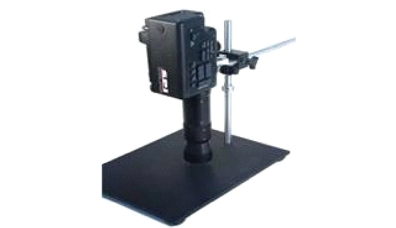
Fig.3 PD300

Fig.4 IRT 7000
However, these thermal microscope imaging systems using cooled infrared detectors are heavy and expensive, and hence find few applications in our country. In order to solve this problem, we developed a thermal microscope imaging system based on an uncooled infrared detector[12-14]in 2008 (Fig.5). In 2012, Japan developed the FSV-GX7700 thermal microscope imaging system, which used an uncooled focal plane detector[15]. Han Jie proposed a thermal microscope imaging system based on the uncooled focal plane detector in 2015[16].
However, the spatial resolution of the thermal microscope imaging system based on an uncooled infrared detector is low. With optical microscanning technology, the spatial resolution of the thermal microscope imaging system can be increased without increasing the detector dimension or reducing the detector unit size[17-20].
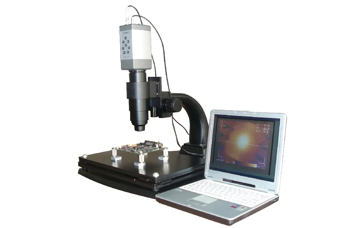
Fig.5 Thermal microscope imaging system
Optical microscanning imaging technologies have been widely used in many fields, such as military reconnaissance, remote image sensing, and scientific research. The low-resolution image sequences, which have microdisplacements between frames, can be obtained by optical microscanning. In addition, by the subsequent reconstruction processing, we can obtain a high-resolution oversample[21-24].
Therefore, we developed an optical microscanning thermal microscope system based on optical plate rotating microscanning technology. The optical microscanning thermal microscope imaging system is composed of an infrared microscope, a rotating optical plate microscanning instrument, an uncooled infrared detector, a computer and a mechanical structure component[25](Fig.6).
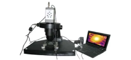
Fig.6 Optical microscanning thermal microscope imaging system
The components of the rotating optical plate microscanning instrument are an infrared optical plate, an electronically controlled rotating platform, a mount for the optical plate and the corresponding controller. Through the infrared objective lens and the microscanning device, the object is imaged by the infrared focal plane array. Then thermal microscope images are displayed on the computer. The microscanning instrument is placed in front of the focal plane array and controlled by the computer in the 2×2 model four-point mechanical microscanning scheme, as shown in Fig.7. The optical plate is at an angle relative to the optical axis. The mechanical device rotates it around the system’s optical axis. We collected four low-resolution images at intervals of 90° from the microscanning zero[26]. Each image had a displacement of half the size of the photosensitive pixel of the detector. The standard 2×2 microscanning location is shown as the upright square in Fig.8.
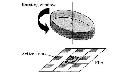
Fig.7 Diagram for microscanning

Fig.8 2×2 microscanning location
The labels 1, 2, 3, and 4 are located in the four quadrants of 45°, 135°, 225°, and 315°, and they represent four standard locations; thus they form a regular upright square. The four low-resolution images collected at the standard locations are sub-sampled, and we can use the sub-sampled images to reconstruct a high-resolution image. The spatial resolution of the imaging system is improved. However, due to unavoidable errors (such as alignment, mechanical vibration, imperfections in the fabrication of the devices and environmental factors), the actual optical microscanning microdisplacement deviates from the regular position, and the microdisplacement position is not a regular upright square (Fig.9). As a result, if we use four images with corresponding locations that are not standardized, the quality of the reconstructed image will be reduced. The resulting quality will be even poorer than that of the image amplified by the original image with a double linear interpolation method.

Fig.9 Actual micro displacement position of four images collected by the thermal microscope imaging system
Therefore, it is essential to calibrate the error to obtain regular 2×2 microscanning undersampling images for direct reconstruction[27]. In this paper, we have proposed an oversample image reconstruction algorithm to calibrate the error, based on a strong diagonal matrix. This technique can obtain regular 2×2 microscanning undersampling images from the real irregular undersampling images, which leads to a high spatial oversample resolution image. In other words, it can reduce the error. In this paper, the algorithm will be referred to as the inter-frame difference oversample reconstruction based on a strong inter-diagonal matrix (SIDM-IDOR).
1 Reconstruction of a High Spatial Oversample Image Based on Irregular Microscanning Images
Assume that the (2M)×(2N) pixel high-resolution oversampling image O is obtained by directly cross-embedding the 4 low-resolution undersampling images O(2i-1, 2j-1),O(2i-1, 2j),O(2i, 2j),O(2i, 2j-1),(wherei= 1,2, …,M;j= 1, 2,N) taken in 2×2 microscanning mode. Since the actual microscanning displacement is irregular (see Fig.9), there are microdisplacements (xt,yt) between thetth (2, 3, 4) low-resolution image gt, and the first low-resolution image g1that is collected at the zero point of the microscanning system. Fig.10 shows a schematic diagram of regular 2×2 microscanning oversample reconstruction. For different processing methods of microdisplacements, there will be different processing algorithms.

Fig.10 Schematic diagram of regular 2×2 microscanning oversample reconstruction.
1.1 Inter-frame difference oversample reconstruction (IDOR)
We present some series expansions for the low-resolution images. The first low-resolution image position is taken to be the origin of our coordinate system[28].
gt(i,j)=O(2i-1+ht,2j-1+kt)=
O(2i-1,2j-1)+
[ht∂/∂i+kt∂/∂j]O(2i-1,2j-1)+
1/2![ht∂/∂i+kt∂/∂j]2O(2i-1,2j-1)+…
(1)
where (t=1, 2, 3, 4), andhtandktare the normalized microdisplacements (the unit is pixel for these variables) between thetth low-resolution image and the first one
ht=xt/2Δ,kt=yt/2Δ
(2)
In Eq.(2),Δis the distance between the centers of the two adjacent pixels in the detector. Using the difference instead of a differential and retaining only the two highest-order terms in the Taylor expansion, we can deduce the following
AX=Y
(3)
where
X=[O(2i-1,2j-1) O(2i,2j-1) O(2i-1,2j) O(2i,2j)]
(4)
X is a regular 2×2 microscanning undersampling image, and
Y=[g1(i,j)g2(i,j)g3(i,j)g4(i,j)]
(5)
Y is a real irregular 2×2 microscanning undersampling image, and
(6)
with
at1=1-ht-kt+htkt,
at2=ht(1-kt),at3=kt(1-ht),at4=htkt
(7)
It is easy to prove that matrix A is invertible if the microdisplacement is determinate and non-overlapping.
X=A-1Y
(8)
Thus, we can obtain a regular 2×2 microscanning undersampling image X (see Fig.8) from the real irregular undersampling image Y (see Fig.9).
1.2 Inter-frame difference oversample reconstruction based on strong inter-diagonal matrix (SIDM-IDOR)
Fig.9 shows that the microdisplacement of an actual microscanning system is irregular, such as in the following example: (0.00, 0.00), (0.03, -0.56), (0.53, -0.55), (0.60, 0.06).
However, the normalized microdisplacement (counterclockwise) is still near the regular microscanning position {(xt0,yt0)}={(0.00, 0.00), (0.00, 0.50), (0.50, 0.50), (0.50, 0.00)}. Also, assuming (xt,yt) is the microdisplacement between the four actual collected images relative to the first regular scanned image, the microdisplacement (xt,yt) can be expressed as
(9)
Let every irregular low-resolution image be expanded as a Taylor series using the corresponding regular low-resolution image as a starting point
gt(i,j)=O(I+Δxt,J+Δyt)=
O(I,J)+[Δxt∂/∂i+Δyt∂/∂j]O(I,J)+
1/2![Δxt∂/∂i+Δyt∂/∂j]2O(I,J)+…
(10)
ParametersIandJare related toi,jandt. ① Ift=1,I=2i-1 andJ=2j-1; ② ift=2,I=2iandJ=2j-1; ③ ift=3,I=2iandJ=2j;and ④ ift=4,I=2i-1 andJ=2j. In these four cases, using the difference instead of a differential in which we keep only the two highest-order terms, we obtain as
(11)
It is not difficult to deduce that
BX=Y
(12)
where
(13)
and
(14)
As for the actual microscanning positions (recall the trapezium shown in Fig.9), it is easy to prove that matrix B is invertible. We obtain as
X=B-1Y
(15)
Thus, we can obtain a regular 2×2 microscanning undersampling image X (see Fig.8) from the real irregular undersampling image Y (see Fig.9).
Comparing coefficient matrix Eq.(14) with coefficient matrix Eq.(7), we can see that under the condition of irregular microscanning, Δxtand Δytare small quantities, buthtandktmay not be. Therefore, the precision of SIDM-IDOR is better than that of IDOR when we use only the two highest-order terms in Eqs.(1)(10). In addition, matrix B is a strong diagonally dominant matrix, but matrix A is not. By the nature of strong diagonally dominant matrices, the calculation of the inverse of matrix B has a higher degree of accuracy than the calculation of the inverse of matrix A when there is an error in matrix A and B. Combining the two factors, we can see that in theory, SIDM-IDOR has a higher precision than IDOR. The microdisplacement of the actual system is easy to calculate, and matrix B-1can be obtained by parsing Δxtand Δyt. Thus, the process of determining X from Y by an algebraic algorithm is fast.
2 Simulation and Actual Thermal Microscope Image Experiment
2.1 Infrared image simulation experiment
In order to quantitatively evaluate our algorithm, we first performed a simulation of the experiment. Based on the actual microdisplacement (trapezium as shown in Fig.9), four low-resolution images (Fig.11b) were created from the high-resolution infrared image (Fig.11a). The results are shown in Fig.12. Fig.12a is the oversampling reconstructed image with IDOR and Fig.12b is the oversampling reconstructed image with the SIDM-IDOR algorithm. To appraise the effects of reconstruction, the parameters of root mean square error (RMSE), peak signal-to-noise ratio (PSNR), general image quality factor (Q), and information entropy (SNT) are shown in Tab.1. By definition, high-quality reconstructed images are more similar to the original than low-quality images; their RMSE approximations are smaller and PSNRs are greater. The quality factor indicates that the more similar the correlation, contrast, and brightness between two images, the larger Q will be, which will be closer to 1.

Fig.11 High-resolution image and microscanning under-sample images

Fig.12 Reconstruction images of IDOR and SDDM-IDOR

ReconstructionmethodRMSEPSNRQSNTIDOR0.059272.72060.98006.7426SIDM-IDOR0.041375.84360.99016.7900
The more information the image contains, the larger the SNT is. We can see that the evaluation parameters with the oversampling reconstruction method SIDM-IDOR are better than the evaluation parameters with the method IDOR. We can conclude that the image reconstructed using the SIDM-IDOR method is more similar to the original image and contains more information.
2.2 Experiments of actual thermal microscope images
To verify the effectiveness of the proposed algorithm in the actual thermal microscope imaging system, we captured four low-resolution images of the target in 2×2 microscanning mode (Fig.13). Fig.14a is the image reconstructed using the IDOR method. Fig.14b is the oversampling image reconstructed using the SIDM-IDOR method proposed in this paper.
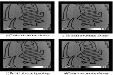
Fig.13 Four real microscanning downsample

Fig.14 Reconstruction of a real microscanning thermal image with different algorithms
It can be seen that the images reconstructed using SIDM-IDOR contain more information than those reconstructed using IDOR. Furthermore, the spatial resolution of the image reconstructed using SIDM-IDOR is better than the spatial resolution of the image reconstructed using IDOR.
3 Conclusion
As researchers continue to pursue high-resolution optical imaging systems, the development of photoelectric detectors always lags behind the requirements of the system. Therefore, it has become an important research direction to make use of optical microscanning techniques in low-grade detectors, in order to realize high-resolution imaging. There is intrinsic error in the optical microscanning machine, which is difficult to avoid completely. Reasonable and effective processing algorithms become the key of practical technology to reduce the impact of the error in the reconstructed images. The SIDM-IDOR algorithm uses the stability of a strictly diagonally dominant matrix to reduce the influence of microdisplacement errors. The technique can obtain regular 2×2 microscanning undersampling images from the real irregular undersampling images, and can then obtain a high spatially oversampled resolution image. Simulations and experiments show that the proposed technique can reduce the optical microscanning errors and improve the system’s spatial resolution. The results show that the proposed method can effectively improve the spatial resolution of thermal microscope imaging systems. The algorithm proposed is simple, fast, and has low computational complexity.
[1] Phillips T J. High performance thermal imaging technology [J]. III-Vs Review, 2002, 15(7):32-34.
[2] Rogalski A. Progress in focal plane array technologies[J]. Progress in Quantum Electronics, 2012, 36(2-3):342-473.
[3] Mai L B. Outline on development and application of FPA thermal imaging sets[J]. Infrared Technology, 2006, 28(9):497-502.
[4] Li Xiangdi, Huang Ying, Zhang Peiqing, et al. Infrared imaging system and applications[J]. Laser & Infrared, 2014, 44(3):229-234.(in Chinese)
[5] Peng Huanliang. The development of the IRFPA thermal imaging technology[J]. Laser & Infrared, 2006, 36(9):776-780.(in Chinese)
[6] Wang H, Dinwiddie R B, Maleki H, et al. IR imaging of integrated circuit power transistors during operation[C]∥Aerosense. Beijing, China: International Society for Optics and Photonics, 2002:80-87.
[7] Li L I. Application of optical methods in microeletronics packaging[J]. Journal of Experimental Mechanics, 2007, 22(3-4): 236-248.
[8] Gao Meijing, Jin Weiqi, Xin L U, et al. Improved row action iterative super-resolution restoration for thermal microscope imaging system[J]. Opto-Electronic Engineering, 2011, 38(9):35-39.(in Chinese)
[9] Mansfield J R. Infrared imaging of skin lesions[C]∥Proceedings of SPIE-The International Society for Optical Engineering, Beijing, China, 2002.
[10] Lee S Y, Tung H W, Chen W C, et al. Thermal actuated solid tunable lens[J]. IEEE Photonics Technology Letters, 2006, 18(21):2191-2193.
[11] Gao Meijing, Jin Weiqi, Wang Haiyan. The new thermal microscope imaging system for electronic device analysis [J]. Electronic Packaging, 2008, 8(4): 41-44.(in Chinese)
[12] Li Y, Yang Z W, Zhu J T, et al.Investigation on the damage evolution in the impacted composite material based on active infrared thermography[J]. Ndt & E International, 2016, 83:114-122.
[13] Abdollahi H, Hajghassem H, Mohajerzadeh S. Simple fabrication of an uncooled Al/SiO2, microcantilever IR detector based on bulk micromachining[J]. Microsystem Technologies, 2014, 20(3):387-396.
[14] Gao M J, Jin W Q, Wang X. Thermal microscope imaging system for semiconductor device and IC invalidation analysis[J].Proc SPIE,2008,6621: 1-8.
[15] Feng Y, Zhao Y, Dong L, et al.High-speed infrared imaging by an uncooled optomechanical focal plane array[J]. Applied Optics, 2015, 54(34):10189-10195.
[16] Han Jie. Research on the key techniques of thermal microscope imaging system[D]. Beijing: Beijing Institute of Technology, 2015: 1-83.(in Chinese)
[17] Zhang Dongxiao, Lu Lin, Li Cuihua, et al. Super-resolution image reconstruction algorithm based on sub-pixel shift [J]. Acta Automatica Sinica, 2104, 40(12):2851-2861.(in Chinese)
[18] Gao M J, Xu J, Tan A L, et al.Error correction based on micro-scanning preprocessing for an optical micro-scanning thermal microscope imaging system[J]. Infrared Physics and Technology, 2017,83: 252-258.
[19] Guan Congrong, Jin Weiqi, Wang Jihui. Application of histogram on micro-scanning position calibration of microscopic thermal imaging[J]. Infrared & Laser Engineering, 2013,42(2):519-523.(in Chinese)
[20] Gao Meijing, Xu Jie, Tan Ailing, et al. Optical micro-scanning zero calibration for a thermal microscope imaging system[C]∥International Symposium on Optoelectronic Technology and Application. International Society for Optics and Photonics, Beijing, China, 2016.
[21] Zhang Haitao, Zhao Dazun. Mathematics theory and realization of aliasing reduction in opto-electric imaging system using microscanning[J]. Acta Optica Sinica,1999,19: 1258-1263.(in Chinese)
[22] Zhang Haitao, Zhao Dazun. Mathematics theory and realization of aliasing reduction in opto electric imaging system using microscanning[J]. Acta Optica Sinica, 1999, 19(9):1649-1654.(in Chinese)
[23] Park S C, Min K P, Kang M G.Super-resolution image reconstruction: a technical overview[J].IEEE Signal Processing Magazine,2003, 20(3): 21-36.
[24] Gillette J C, Stadtmiller T M, Hardie R C. Aliasing reduction in staring infrared images utilizing subpixel techniques[J]. Optical Engineering, 1995, 34(11):3130-3137.
[25] Gao Meijing, Jin Weiqi, Wang Xia. Design and implementation of optical micro-scanning thermal microscope imaging system with high resolution[J]. Chinese Journal of Scientific Instrument, 2009,30(5):1037-1041.(in Chinese)
[26] Gao Meijing, Jin Weiqi, Wang Xia, et al. Zero calibration for the designed microscanning thermal microscopic imaging system[J]. Acta Optica Sinica, 2009, 29(29):2175-2179.(in Chinese)
[27] Gao M J, Wang J Y, Xu W, et al. High-resolution over-sampling reconstruction algorithm for a microscanning thermal microscope imaging system[J]. Infrared Physics & Technology, 2016, 76:661-666.
[28] Gao Meijing, Jin Weiqi, Wang Xia, et al. Inter-frame difference oversample reconstruction for optical microscanning thermal microscope imaging system[J]. Transactions of Beijing Institute of Technology, 2009, 29(8):704-707.(in Chinese)
 Journal of Beijing Institute of Technology2018年1期
- Journal of Beijing Institute of Technology的其它文章
- Quantitative Method of the Structural Damage Identification of Gas Explosion Based on Case Study: The Shanxi “11.23” Explosion Investigation
- Compressional Deformation in Indentation Process for Microlens Array Mold
- Development and Verification of the Equilibrium Strategy for Batteries in Electric Vehicles
- Modeling and Optimization of Heat Dissipation Structure of EV Battery Pack
- Scheduling Optimization of Space Object Observations for Radar
- Chaff Jamming Recognition of Radar
