Streamline similarity method for flow distributions and shock losses at the impeller inlet of the centrifugal pump *
Zh. Zhang
Streamline similarity method for flow distributions and shock losses at the impeller inlet of the centrifugal pump*
Zh. Zhang

Pumps, streamline similarity method, flow distribution, shock loss, structural constant
Introduction
In industrial applications, both the hydraulic efficiency and the operation safety of a pump highly depend on the flow dynamic behaviour of water flows from the pump inlet to the exit. The undesirable flow dynamic behaviour of a pump comprises instability in the pump characteristics, shock loss leading to the drop of the hydraulic efficiency, cavitation as well as rotating stall and many other phenomena. Although some undesirable flow phenomena are related to the exit flow out of the impeller owing to the interaction between the impeller and the guide wanes and have been mainly investigated by numerical methods[1-4], in many cases, however, the origin of a great number of undesirable flow phenomena has often been con- firmed at the inlet area of the pump. To the first, the unfavourable rotating stall has its origin in the inlet flow[5]. To the second, the cavitation around the leading edge of the impeller blades remains a serious problem in many cases. To its suppression one often applies a pre-device like the inducer upstream of the pump impeller, referring to [6], for instance. The main subject of designing a high performance pump is actually to specify the real flow conditions at the pump inlet and to layout the geometrical profile of impeller blades to match that flow. To be noted is that the objective of specifying the trailing edge of the impeller blades of a pump mainly aims to specify the designed specific work.
In general, the velocity distribution along the leading edge of impeller blades is in no case uniform because of the streamline curvatures. This is so even though the flow in the suction pipe is uniform and irrotational (potential flow). Meridian velocities on the hub and shroud sides of the pump impeller may differ by a factor two or even more[7-10]. Although such a non-uniform velocity distribution is much significant in both determining the geometrical design of the impeller blades and influencing all subsequent flows, with regard to computations there exists hardly any favourable and explicit method. Apparently, only the so-called streamline curvature method to solve the velocity gradient equation has been used for that purpose. The method was developed based on the general theory in Ref. [11] and has been primarily applied in the turbocompressors[8-10]. It is, however, a method with intensive iterative computations, which often suffer from the divergence problem and also take much more computation time. In addition, the velocity gradient equation (a partial differential equation) was uniquely solved by the finite difference method rather than by the integration. The other methods to acquire knowledge about the respective non-uniform velocity distribution have so far been, among very few investigations, limited to experimen- tal measurements[12,13].
The occurrence of flow separations and the resulting shock losses on the leading edge of the impeller blades are related to the pump operations out of the design point. Up to now, there practically exists no analysis for computing the mean of the related shock losses because of the non-uniformity of the flow distribution. This shortage in the analysis strongly confuses the explanation and interpretation of the form of the efficiency characteristic of a pump. With other words it is still not quite clear, how the shock loss physically and computationally depends on the flow rate.
The objective of the present paper is to work out a computational method that can be easily applied to accurately determine the flow distribution at the pump inlet, especially along the leading edge of the impeller blades. As mentioned above, the available flow information at the impeller inlet serves to layout as well as to check the geometrical profile of the impeller blades. The simplest way to work out such a method is obviously to assume the flow in the suction pipe to be uniform and irrotational. The flow of this form is the simplest potential flow. Because the flow of this property directly approaches the leading edge of the impeller blades, it can be considered to be frictionless. The irrotationality condition of the flow then remains. The flow dynamic laws used in this paper to derive the new computational method are momentum and mass conservation laws as well as the laws of potential flows. To solve the velocity gradient equa- tion, the streamline distribution at the impeller inlet is assumed to be similar, i.e., independent of the flow rate. The computational method, thus, is called the streamline similarity method (SSM) for pump flows.
Based on the use of this method the overall shock loss at the impeller inlet becomes predictable and should be computed. This also aims to reveal the physical background of shock losses in function of the flow rate.
It should be further mentioned that the SSM presented in this paper had also be successfully applied to the exit flow of a Francis turbine which operates both at the nominal flow rate and the flow rate out of the design point[14]. As long as the flow at the impeller inlet can be considered to be a potential flow (irrotational and thus constant total pressure) and the flow friction effect can be neglected, the irrota- tionality condition of the flow at the impeller exit should remain unchanged. At the nominal flow rate, the exit flow out of the turbine impeller possesses only axial and radial velocity components. It is then comparable with the two-dimensional flow at the inlet of a pump: with similar geometrical distributions of streamlines. In Ref. [14], the computational method was simply referred to private communication, without giving the detailed derivations.
1. Potential flow theory for pumps
1.1 Momentum equation and coordinate transforma- tion
Theflowinthesuctionpipeisassumedtobe one- dimensional, uniform and frictionless (Fig. 1). Such a flow is a potential flow of the simplest form. When reaching the leading edge of the impeller blades, the flow then becomes two-dimensional because of the existence of the radial velocity component. Such a fri- ctionlesstwo-dimensionalflow with vanishing circum- ferential velocity component can be described by the Eulerian momentum equations for frictionless flow in the cylindrical coordinate system as


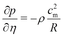
The first equation is written here only for completeness and will not be further considered throughout the present paper. Obviously, as stated in Eq. (4), there is a pressure gradient perpendicular to the streamlines.
Because the flow in the suction pipe is assumed to be potential flow, i.e., the flow with uniform distribution of the total pressure, such a flow must so maintain up to the leading edge of the impeller blades. The Bernoulli equation for constant total pressure and its transverse derivative are then given by

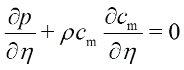
Together with Eq. (4) one obtains


With respect to Eq. (7) this last equation can then be written as

In the description of the streamline curvature method, for instance, in Refs. [8, 9], the above equation is called velocity gradient equation. Its solution was uniquely based on the finite difference method. As will be shown below in Section 2, Eq. (10) will be solved by integration.


1.2 Mass conservation equation

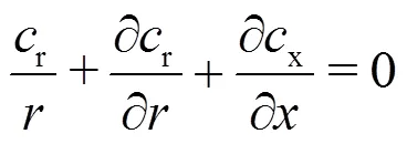


Thus, Eq. (12) is rewritten as

or owing to Eqs. (8) and (11)


2. Flow distributions along the leading edge of im- peller blades
2.1 General formulae of velocity distributions


Fig. 1 Flow in the meridian plane of the impeller

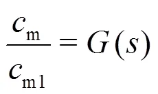

From Eq. (18) the distribution of the meridian velocity along the leading edge of an impeller blade is given by


Employing Eq. (20) one obtains


The distribution of the meridian velocity com- ponent along the leading edge of an impeller blade is then computed as


2.2 Special case analysis for velocity distributions


and
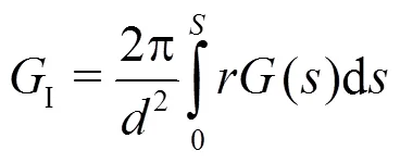


Obviously, the flat distribution of is obtained at small ratio . In Fig. 2, this means a large ratio .
2.2.2 Special Case 2: Concentric streamlines


Basically, the geometrical configuration of con- centric streamlines leads to the decrease of the radius of curvature of the shroud side profile and, thus, to an enlarged non-uniform velocity distribution. This can be demonstrated by considering again the curvature radius on the hub side. Because , one gets . This value is evidently smaller than the practical values from 0.6 to 0.8, which have been applied in Fig. 2. In Fig. 3, the distribution of according to Eq. (33) and for is compared with the real caseof from Fig. 2. Obviously, the con- centric circular profiles on the hub and shroud sides should never be suggested. Otherwise, it would likely result in local flow separation and cavitation.


This result should be used with caution because concentric circular profiles have just been considered as unfavorable.
2.2.3Special Case 3: Pseudo uniform velocity distri- bution


Because the assumption of uniform velocity distribution along the leading edge of impeller blades does not reflect the reality (designated as pseudo uniform), as confirmed in Fig. 2, the above equation only represents a rough approximation.


And, consequently


Fig.4Inlet flow of an axial pump

2.3 Pressure distributions
As long as the velocity distribution along the leading edge of impeller blades of a pump has been calculated, the related pressure distribution can imme- diately be calculated based on the Bernoulli equation given in Eq. (5)


3. Aplications and validations for flow distribution
3.1 Numerical method and computational steps


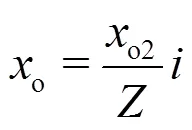

Fig. 5 Determination of the origins and curvatures of the curved streamlines by interpolation


Remarkably, the velocity distribution is again highly non-uniform, comparable to that in Ref. [7] where the velocity changes from 2.5 m/s on the hub side to 6 m/s on the shroud side.

Furthermore, the pressure distribution along the leading edge can be calculated according to Eq. (38). The computational result is shown in Fig. 6(c) (with the pressure on the shroud side as reference). The static pressure on the shroud side is a minimum and in many cases could even be negative, which means that flow separation and cavitation take place. If this occurs, none of the computational results in Fig. 6 will be true.

Fig.6 Computational results and comparison between accurate calculations and the approximations for a pump (KWO) with
3.2 Comparison of calculations with an earlier mea- surement


Fig. 7Comparison of calculations by using Eqs. (25) and (29) with measurements (Sulzer 1992)
At this point, the author would like to indicate that there have been hardly any numerical simulations of such a flow distribution that can be used as the reference. With other words, almost all published CFD simulations of the pump flows were performed with doubtful flow condition at the impeller inlet. Most likely and unfortunately, the condition of the pseudo uniform velocity distribution according to the special case 3 in Section 2.2 has been assumed. For this reason, the velocity distribution according to Eq. (25) of the geometrical character should always be applied to validate CFD simulations, at least and each time before the complex flows both within and out of the impeller will be further simulated by CFD.
4. Shock loss at the impeller inlet
4.1 Shock loss formula
It should be mentioned that the shock loss at the impeller inlet behaves as a much significant loss in the pump flow. Its computation, however, seemed since ever to be impossible because of the non-uniform velocity distribution. In this section and based on the obtained velocity distribution along the leading edge of impeller blades (Section2), a very practical formula for the shock loss will be presented.
Pumps are normally designed for operating at the nominal flow rate, at which the leading edges of impeller blades are configured to ensure the shockless entrance of the flow into the impeller. The related blade angle and its distribution along the blade leading edge should be designed with respect to the velocity distribution that has been calculated by Eq. (25) for the case of straight flow without pre-rotation, as given by


At other flow rate, as long as all streamlines remain constant, the relative flow angle is given by


Fig. 8Flow and velocity triangles at the impeller inlet, used for determining the shock loss at the partial load of the pump


4.2 Structural constants
In Eq. (50), the second structural constant has been introduced which is defined as


Fig.9Shock loss at the impeller inlet of a centrifugal pump


4.3 Limitation of using the structural constants


Fig. 10 Induced flow stagnation at the impeller inlet at low flow rate
5. Summary and outlook
For a long time, the hydraulic characteristics of both the pump and the turbine could only be obtained by measurements; this is still the case today. There has been no reliable analytical method for computing such hydraulic characteristics. One main reason for this shortage in the related technology is the lack of the fundamentals for analytically computing the non- uniform flow distributions, for instance, at the pump inlet. Such a non-uniformity of the velocity distribu- tion basically determines the geometrical design of the impeller of the pump. At the operations out of the design point, it also determines the shock loss in the flow at the impeller inlet. As a matter of fact, the shock loss behaves as a highly significant loss in such pump flows.

The method provides a completely new way to compute the pump inlet flow without having to regard the flow states (laminar or turbulent) and to use any turbulence models. Especially, the derived velocity distribution at the impeller inlet can be applied to validate CFD simulations, before the complex flows within and out of the impeller will be further simu- lated.
Because of the geometrical similarity of the streamline distribution at the impeller inlet of the pump, the SSM can also be directly applied to non- uniform flows at the impeller exit of a Francis turbine, aiming to accurately average all related flow para- meters. In reality, because such an application has already been confirmed to be highly successful[14], the method presented in this paper for pump flows has, thus, also been indirectly validated.
The method can be applied to the pump flow down to about 60% of the nominal flow rate.
For future investigations aiming to achieve the advanced hydraulic performances in pump and turbine flows, the SSM with the use of two structural cons- tants will certainly play a significant role and likely release the standard design for pumps and turbines as a function of the specific speed of the machines.
[1] Shi F., Tsukamoto H. Numerical study of pressure fluctua- tions caused by impeller-diffuser interaction in a diffuser pump stage [J]., 2001, 123(3): 466-474.
[2] Muggli F., Eisele K., Zhang Zh. et al. Numerical investi- gations of the flow in a pump turbine in pump mode [C]., London, UK, 1999.
[3] Feng J., Benra F., Dohmen H. Unsteady flow visualization at part-load conditions of a radial diffuser pump: By PIV and CFD [J]., 2009, 12(1): 65-72.
[4] Guleren K., Pinarbasi A. Numerical simulation of the stalled flow within a vaned centrifugal pump [J]., 2004, 218: 1-10.
[5] Zhang Zh. Rotating stall mechanism and stability control in the pump flows [J]., 2011, 225: 779-788.
[6] Hong S., Kim D., Kim J. et al. Study on inducer and impeller of a centrifugal pump for a rocket engine turbo- pump [J]., 2013, 227: 311-319.
[7] Pfleiderer K. Die kreiselpumpen für flüssigkeiten und gase [M]. Berlin, Germany: Springer-Verlag, 1955, 126.
[8] Casey M., Roth P. A streamline curvature throughflow method for radial turbocompressors [C]., Solihull, UK,1984.
[9] Casey M., Robinson C. A new streamline curvature throughflow method for radial turbomachinery [J].2008, 132(3): 2119-2130.
[10] Gong W. Q., Wu R. K., Zhang B. A new finite difference method to solve the velocity gradient equation in stream- line curvature method [J]., 2016, 8(9): 1-13.
[11] Wu C. H. A general theory of three-dimensional flow in subsonic and supersonic turbomachines of axial-, radial-, and mixed-flow types [R]. Washington DC, USA: NACA, 1952, NACA-TN-2604.
[12]Stoffel B., Weiss K. Different types and locations of part-load recirculations in centrifugal pumps found from LDA measurements [C]., Valencia, Spain, 1996, II: 1034-1044.
[13] Eisele K. Global und LDA messungen am radialpumpen- laufrad la 033.112 mit unbeschaufeltem und beschaufel- tem diffusor [R]. Sulzer Innotec Report, 1992, IT 1773.
[14]Zhang Zh., Titzschkau M. Self-validated calculation of characteristics of a Francis turbine and the mechanism of the S-shape operational instability [J].,2012, 15(3): 032036.
[15]Gülich J. Centrifugal pumps [M]. 2nd Edition, Berlin, Germany: Springer-Verlag, 2010, (Fig. 7.4).
Appendix: Computation of the parameter


This equation can also be written as

and
From Eq. (a4) one obtains

This can also be written as


From Eq. (a2) one obtains then

or

From Eq. (a5) one obtains

It can be further written as

For the same reason as in (1) it follows from Eq. (a2) that

and further that

(3) Combination
Equations (a7) and (a11) are inserted into Eq. (a1), leading to

For further simplification of this equation follo- wing relationships are applied:
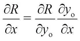
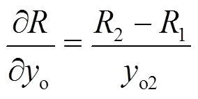
Equations (a9) and (a13) are then inserted into Eq. (a14). Finally one obtains

(September 12, 2016, Revised June 27, 2017)
©China Ship Scientific Research Center 2018
Zh. Zhang (1957-),Male, Ph. D.
Zh. Zhang,
E-mail: zhengji.zhang@hotmail.com
- 水动力学研究与进展 B辑的其它文章
- Overview of SPH-ALE applications for hydraulic turbines in ANDRITZ Hydro*
- Analysis of the hydrological safety of dams combining two numerical tools: Iber and DualSPHysics *
- Impacts of bridge piers on water level during ice jammed period in bend channel–An experimental study *
- DualSPHysics: A numerical tool to simulate real breakwaters *
- SPH numerical investigation of the characteristics of an oscillating hydraulic jump at an abrupt drop *
- Five-equation and robust three-equation methods for solution verification of large eddy simulation *

