Numerical interpretation of transient permeability test in tight rockChong Cao
E-mail address:chong.cao@mail.mcgill.ca.
Peer review under responsibility of Institute of Rock and Soil Mechanics,Chinese Academy of Sciences.
https://doi.org/10.1016/j.jrmge.2017.07.009
1674-7755Ⓒ2018 Institute of Rock and Soil Mechanics,Chinese Academy of Sciences.Production and hosting by Elsevier B.V.This is an open access article under the CC BY-NC-ND license(http://creativecommons.org/licenses/by-nc-nd/4.0/).
1.Introduction
Permeability has been identified as an important parameter influencing environmental geomechanics problems that deal with groundwater seepage flow(Zhou et al.,2011),deep geological disposal of radioactive nuclear wastes(Delage et al.,2010;Wang et al.,2014),energy extraction from geothermal reservoirs(Tomac and Gutierrez,2017),and geological sequestration of carbon dioxide(Siriwardane et al.,2016).Considerable laboratory efforts have been devoted to measuring the permeability characteristics of porous geomaterials under different mechanical and environmental conditions(Siriwardane et al.,2009;Chen et al.,2014;Pan et al.,2015;Zhang,2016).
The pulse-decay method is widely employed to estimate the transport properties of low-permeability rocks(permeabilityK<10-18m2),using either liquid(e.g.water and ethanol)or gas(e.g.nitrogen,argon,and helium)as the permeating fluid(see Table 1).This technique mainly involves the instantaneous pressurization of a fluid volume that is in direct contact with the deformable porous medium and allowing the pore pressure to diffuse through the permeable rock matrix.The decay pattern of the pressure within the fluid-filled pressurization system can be monitored and related to the permeability of the rock quantitatively.The transient test overcomes the difficulties of applying extremely low flow rates and continuing painfully long time required for performing steady-state test on tight rocks.
For hydraulic pulse test,the interpretation of experimental results relies on the numerical analysis of the fluid pressure decay process within pressurized cavity.The coupled hydro-mechanical modeling of hydraulic pulse diffusion through rock matrix should take into consideration the deformability of porous skeleton and the compressibility of permeating fluid.In the conventional mathematical formulation of hydraulic pulse test,it is assumed that both the pressurized cavity and the pore space of the rock matrix are completely saturated with water.However,laboratory experiences show that the air inclusions within the pressurization system cannot be entirely eliminated.The presence of entrapped air bubbles can significantly alter the compressibility of the air-water mixture (Schuurman,1966;Fredlund,1976;Nguyen and Selvadurai,1995;Scherer,2006),which may influence the transient diffusion of pore water pressure.
Little literature deals with the effects of entrapped air on permeability measurement.Keller and Kamp(1992)presented a method for considering storage due to entrapped air in slug test analysis.They suggested that the air present in the gravel pack or formation surrounding the piezometer intake can increase the storage capacity of the piezometer and thus retard the recovery of water levels due to the high compressibility of air.The delayed hydraulic response may lead to the underestimation of permeability.Scherer(2008)investigated the effects of air inclusions within pore liquid on steady-state permeability test,taking into account the pressure-dependent compressibility of air-watermixture.The analysis results show that the time required to reach steady flow can be significantly increased by the presence of entrapped air within pore liquid.The general implication of these studies is that the pressurization system should be de-aired and the rock samples should be completely saturated before the permeability tests.
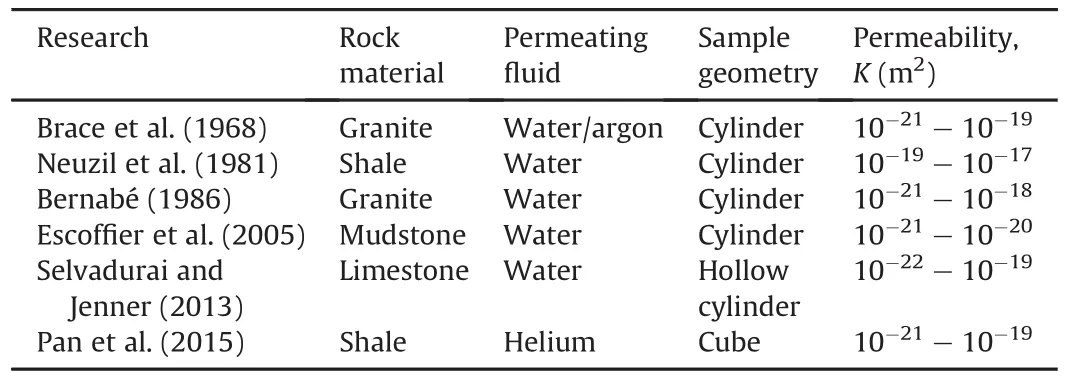
Table 1Selected transient pulse tests on tight rocks.
In this context,the permeability of Cobourg limestone is measured by radial flow hydraulic pulse test.The pressurization system is completely sealed with Marine epoxy to avoid any possible pressure leakage.Vacuum suction is applied to the central cylindrical cavity for removing entrapped air bubbles.Pressure pulses in the range of 200-700 kPa have been applied to the inner cylindrical cavity.The proposed finite difference algorithm is capable of simulating the transient diffusion of pore water pressure through the saturated rock matrix as well as considering the influences of entrapped air bubbles within the pressurized cavity.This method introduces the pressure-dependent compressibility of the air-water mixture into the numerical analysis.Special attention will be given to the interpretation of transient tests under different pressure levels and variable air fractions.
2.Radial flow hydraulic pulse test
The geometric configuration of a typical rock sample utilized for radial flow permeability test is shown in Fig.1.The rock cylinder contains an inner cavity with diameter of 2a,outer diameter of 2band height ofH.The hydraulic pulse is applied to the inner cylindrical cavity and allowed to diffuse through the tight rock matrix.The gradual dissipation of the cavity pressure can be recorded and then interpreted by either analytical or numerical modeling.
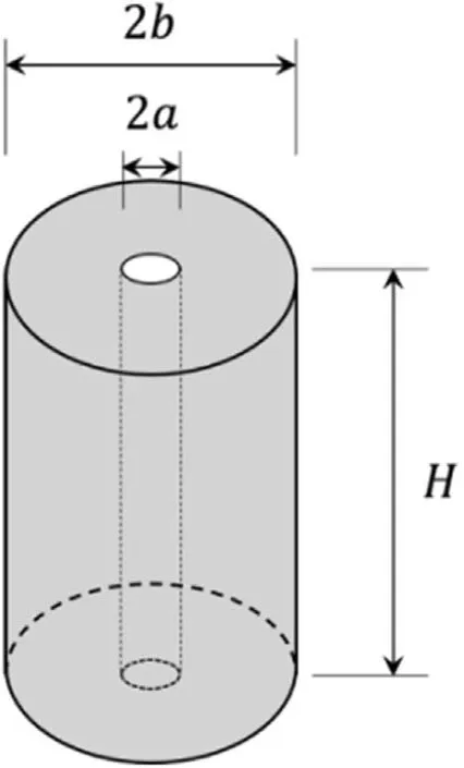
Fig.1.Geometry of rock sample.
2.1.Analytical modeling
According to Darcy’s law,the fluid velocity within a hydraulically isotropic rock can be expressed in the form of

wherep(x,t)represents the pore water pressure distribution at timet,x indicates the space coordinates within rock matrix,μis the dynamic viscosity of water,andKdenotes the intrinsic permeability of the rock.
The mass conservation law for a deformable porous medium saturated with a compressible fluid states that

whereS=nCw+Ceffgives the specific storage of the porous medium,nis the rock porosity,Cwrepresents the compressibility of the pore water,andCeffdenotes the effective compressibility of the porous skeleton.
Considering the experimental arrangement for radial flow permeability test,the governing equation for the transient diffusion of hydraulic pulse through the cylindrical water-saturated rock is expressed as(Selvadurai and Carnaffan,1997;Selvadurai and Jenner,2013):
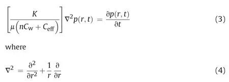
Eq.(4)is the radially symmetric form of Laplace’s operator in the cylindrical polar coordinate system.
In order to obtain an analytical solution for the hydraulic pulse decay,it is assumed that the pressurized central cavity(r=a)is located in an extremely large porous medium(r→+∞).Previous analysis shows that the difference between semi-infinite and finite cylinders for short-duration pulse tests of typical low-permeability materials is marginal(Selvadurai and Carnaffan,1997).Thus,for zero-maintained pressure at the remotely located outer boundary,we have

The kinematic constraint for the pressurized fluid within the cavity requires that the rate at which water moves from the pressurized cavity into the porous medium,as expressed by Darcy’s law applied to the fluid-rock interface,must be identical to the volume expansion rate of the cavity fluid resulting from hydraulic pulse decay,which is written as

whereVwis the volume of the pressurized fluid within the central cavity.
The initial conditions for the transient pulse test are specified as

Eq.(7)indicates that the cavity fluid is subjected to a hydraulic pulsep0,and the rock matrix contains no residual hydraulic gradients before testing.
A convenient analytical solution to the radially symmetric flow has been obtained by applying Laplace transform(Carslaw and Jaeger,1959;Cooper et al.,1967;Bredehoeft and Papadopulos,1980),and the fluid pressure decay around the central cavity can be expressed as

whereJz(u)andYz(u)denote Bessel functions of the first-and second kind of orderz(z=0,1),respectively;uindicates the integration variable;and the dimensionless parametersαandβare given by

2.2.Entrapped air bubbles
The experimental experience in this research shows that the air inclusions within the pressurized fluid cannot be entirely eliminated,although significant efforts have been taken to remove air from the pressurization system.The presence of entrapped air within the central cavity can significantly alter the compressibility of the pressurized fluid.As fluid pressure builds up in the cavity,the entrapped air bubbles are simultaneously compressed.Because of the much higher compressibility for air,the effective compression of the air water mixture can be appreciably increased and thus the pressurization process is slowed down.On the other hand,as the hydraulic pulse decays in the cavity,entrapped air bubbles can expand in volume and therefore the pressure dissipation is considerably delayed.Consequently,the theoretical interpretation of transient pulse tests may lead to an inaccurate estimation of the rock permeability.
Assuming that the air inclusions in the pressurized fluids are in the form of distributed bubbles and the air solubility in water can be ignored,the equivalent compressibility of air-water mixture can be expressed as(Schuurman,1966;Fredlund,1976;Nguyen and Selvadurai,1995;Scherer,2006):

whereP=p+P0denotes the absolute air pressure,P0=101 kPa represents the atmosphere pressure,andφ0gives the initial air fraction by volume.The compressibility of pure water is specified asCw=4.54×10⁻¹⁰Pa-1under standard temperature and pressure(White,1986).
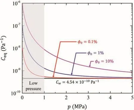
Fig.2.Compressibility of air-water mixture.
The influence of entrapped air bubbles on the compressibility of a pressurized air-water mixture is shown in Fig.2.It is clearly observed that air inclusions can increase the fluid compressibility by several orders of magnitude at low-level hydraulic pulses.As the fluid pressure increases,the compressibility of the air-water mixture decreases and tends to approach pure water compressibility.Therefore,the pressure-dependent compressibility of the air-water mixture will substantially alter the hydraulic pulse decay process.
2.3.Numerical solution
Due to the existence of entrapped air within pressurized cavity,the boundary condition around the inner fluid-rock interface becomes highly nonlinear,which may defy analytical modeling.In order to quantitatively account for the influences of entrapped air bubbles and pressure-dependent fluid compressibility on the results of hydraulic pulse tests,a finite difference algorithm is developed for modeling the transient diffusion of pore water pressure through the saturated rock matrix.The axisymmetric one-dimensional domain is divided intoNpoints in therdirection.
The Crank-Nicolson finite difference approximation for pressure diffusion equation can be written as(Wang and Anderson,1982):

where ω =0.5 is the weighting parameter,and ξ=K/[μ(nCw+Ceff)]represents the pore pressure diffusion coefficient.Solving foryields

The initial conditions for the hollow cylinder can be specified as

The zero-pressure boundary condition at the outer surface exposed to water reservoir is written as

The boundary conditions at inner rock-fluid interface can be approximated with finite difference algorithm as

The cavity pressure at time step(m+1)can be expressed as

To account for air effect,the water compressibilityCwis replaced by the pressure-dependentCeqas

Herein,in order to obtain cavity pressure at each time step(m+1),the equivalent compressibility of air-water mixture calculated from pore pressure value at previous time step(m)is being used.
On the other hand,the amount of entrapped air bubbles within the pressurized fluids can also influence the establishment of hydraulic pulse.Since the build-up period of cavity pressure is supposed to be very short and the rock permeability is relatively low,the instantaneous penetration of pressurized fluid into rock matrix during establishing hydraulic pulse can be neglected.Therefore,the nonlinear cavity pressure build-up can be described as

Eq.(19)can be easily solved using finite difference algorithm as

whereqis the constant volumetric flow rate into cavity.
3.Experimental investigation
The argillaceous Cobourg limestone is being considered as a suitable host rock for the long-term storage of low- and intermediate-level nuclear waste(NWMO,2011).The selected limestone formation is seismically quiet and geomechanically stable.The in situ permeability has been measured to be between 10-20m2and 10-18m2.The extremely low permeability characteristic favors Cobourg limestone as an effective barrier to radionuclide migration.
3.1.Sample preparation
Blocks of the Cobourg limestone were sampled from the Saint Mary’s quarry in Bowmanville,ON,Canada.Small cylindrical samples were cored from the large block and cut into proper length.The Cobourg limestone mainly contains two distinct compositions:the lighter carbonate nodular rock,and the darker argillaceous material.The argillaceous partings in a quartzitic rock give the Cobourg limestone a nominally stratified appearance.Major mineralogical components of the rock include 81%of calcite,8%of dolomite,3%of quartz,and 6%of sheet silicates.The mechanical properties for Cobourg limestone are summarized in Table 2.
The diameter of the tested cylindrical rock sample is 101.6 mm and its height is 190 mm.The central cavity is measured as 25.4 mm in diameter.The chosen sample is cored parallel to the nominal bedding plane and thus the stratification is considered as nominally vertical.Both upper and lower surfaces of the rock sample are attached to stainless steel plates using Marine epoxy supplied by LePage™.All connections to the pressurization system are also sealed with epoxy in order to eliminate pressure leakage.The sealing techniques are shown in Fig.3.The upper steel plate contains one threaded cavity,which can be connected to the pressurization system through a nipple.
3.2.Experimental facility
The pressurization system(see Fig.4)includes a cross that has been connected to the sample cavity,pressure transducer,de-airing pipe and water inlet.The water inletpipe measures 3 mm(1/8 inch)in diameter and goes all the way down to the bottom end of central cavity.This special set-up ensures that water flows into the cavity bottom and flushes out any residual air bubbles through the top deairing pipe.The total mass of pressurized fluid within the cylindrical cavity and connected fittings is measured to be(108.9±1)g(Vw=1.089×105mm3).
The vacuum chamber is utilized to saturate the rock sample with de-aired water(see Fig.5).Vacuum condition is produced by forcing compressed air through a cylindrical Venturi vacuum pump(Vaccon JS-200-AA6 generating vacuum level up to 28 inches of Hg(-94.8 kPa)).As the air exits through the pump nozzle,it expands in volume and increases in velocity to supersonic speed before entering the diffuser.This creates a constant vacuum flow at the suction port,which is connected to the chamber.Sealing has been provided by the rubber O-ring.The entrapped air bubbles can therefore be extracted from the pores of rock sample.For completely removing residual air fraction from the pressurization system through vacuum suction,another cylindrical Venturi vacuum pump is connected to the de-airing valve(see Fig.6).The entrapped air bubbles can be extracted through the de-airing pipe.
The experimental set-up for radial flow hydraulic pulse test is schematically shown in Fig.7.The saturated Cobourg limestonesample is submerged in water reservoir without any axial or confining stress.The water temperature is measured using an Omega thermocouple(Type K hermetically sealed tip insulated design with 24 AWG Stranded).De-aired water is pumped into the cylindrical cavity for building up the hydraulic pulses.Rigid metal pipes have been utilized for connecting the pump(Lab Alliance Series I providing flow rate of 0.01-10 mL/min)with the pressurization system.The pulse decay within cavity is monitored with a Honeywell pressure transducer(Model TJE with 300 psi(1 psi=6.895 kPa)range and 0.1%accuracy)and readings are taken every second through the DasyLab data acquisition system.

Table 2Mechanical properties for Cobourg limestone.
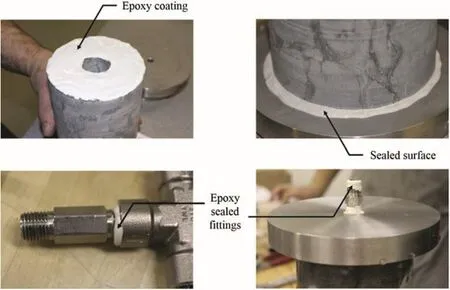
Fig.3.Marine epoxy sealing.
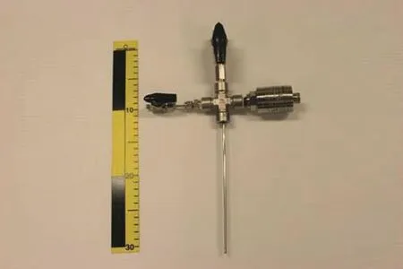
Fig.4.Pressurization system.
3.3.Test procedures
The experimental procedures for performing transient pulse tests on the hollow cylinder of Cobourg limestone are summarized as follows:
(1)The limestone sample is saturated under vacuum condition(-90 kPa)for 7 d.The saturated rock cylinder is then submerged in water in the testing chamber to allow for 24-h dissipation of residual negative pressure.
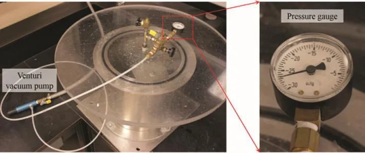
Fig.5.Vacuum chamber.
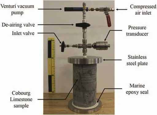
Fig.6.Sample assembly.
(2)In order to eliminate any entrapped air bubbles from the central cavity and fittings,vacuum suction is applied to the de-airing pipe before conducting transient pulse tests on Cobourg limestone sample.The cavity pressure is maintained at-86 kPa by a Venturi pump.During the vacuum suction process,the water inlet valve should be closed while the deairing valve connected to the Venturi pump should stay open.The vacuum suction is turned off after a 24-h de-airing period and a further 24-h is needed for complete dissipation of the residual negative pressure within the rock matrix.
(3)The hydraulic pulse is established by pumping de-aired water into the fluid-filled cavity at a constant flow rate of 0.5-2 mL/min.Upon attainment of the prescribed internal pressure,the water inlet valve is closed and the pump is stopped immediately.The cavity pressure decay is monitored with a pressure transducer and readings are taken every 1 s.
(4)The data acquisition is terminated after 30 min and the deairing valve is opened to allow for 12-h dissipation of any excess pore pressures that remain in the sample.
(5)The procedure is repeated for different hydraulic pulses to obtain repeatable results.
4.Transient test results
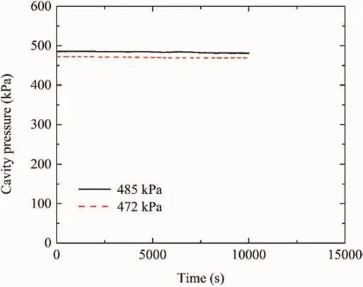
Fig.8.Sealing test results.
The room temperature within the time of pulse decay was(23 ± 0.5)°C.In order to check the effectiveness of epoxy sealing,several sealing experiments were conducted on a water-filled stainless steel tube.The entire pressurization system was immersed under water for eliminating any possible influences of ambient temperature changes.The pressure pulses applied within the sealed steel tube were kept in the range of 400-500 kPa.The drop in the tube pressure is relatively small(less than 1%)over time duration of 10,000 s,as illustrated in Fig.8.This confirms that the Marine epoxy is a successful sealing material for performing a hydraulic pulse test.
Two sets of consecutive pulse tests were conducted on the Cobourg limestone sample.The cavity pressure was first allowed to increase to around 700 kPa level(695 kPa and 725 kPa).De-aired water,at a constant flow rate of 2 mL/min,was pumped into thefluid-filled cavity.The time needed to attain the pressure pulse was recorded at about 5 s for these transient tests.Then,the cavity pressure was allowed to increase to around 200 kPa level(193 kPa and 200 kPa)and the pump flow rate was reduced to 0.5 mL/min.The time required to reach these pressure pulses was around 10 s.
The experimental results for pressure decay within the pressurized cavity are compared with numerical predictions in Fig.9.The computational estimations of cavity pressure decay were determined for several choices ofKvalues ranging from 10-21m2to 10-18m2without considering trapped air.This graphical representation allows the target permeability range to be narrowed down.The exact value of permeability can be conveniently obtained by closely matching the numerical calculations with each experimental pressure decay curve.It can be clearly observed that the higher the initial cavity pressure is,the faster the hydraulic pulse decays.Therefore,the rock permeability is estimated to be 8×10-20m2and 3×10-19m2for initial cavity pressures of 200 kPa and 700 kPa,respectively.
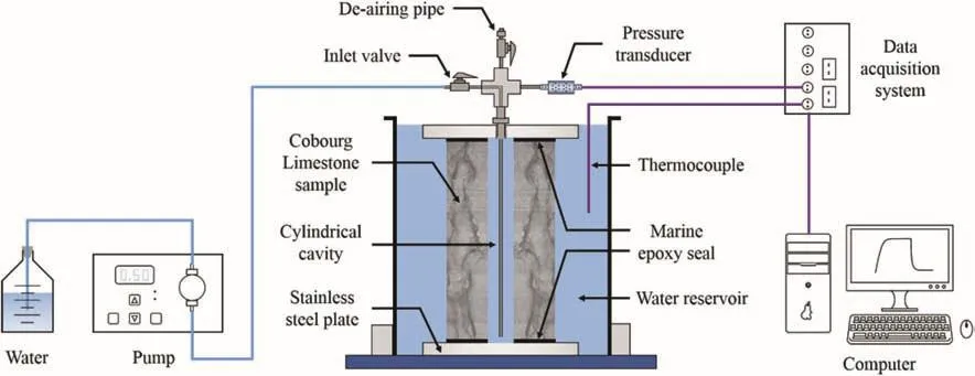
Fig.7.Experimental set-up for radial flow hydraulic pulse test.
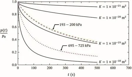
Fig.9.Pressure pulse decay curves.
The disagreement between the interpreted permeabilities for low and high pulse pressures could be explained by air bubble effects.The theoretical pressure build-up in the central cavity is very fast as a result of the small compressibility of pure water.Since the existence of air within water may increase the compressibility of the air-water mixture,the cavity pressure build-up can be delayed and become highly nonlinear.Therefore,the amount of entrapped air bubbles within pressurized fluids can be estimated based on the recorded cavity pressure build-up curves.The same air bubble fraction ofφ0=0.1%was obtained for the two different flow rates of 0.5 mL/min and 2 mL/min,as shown in Fig.10a.
In order to account for the pressure-dependent compressibility of an air-water mixture,the computational study for radial flow hydraulic pulse test was performed at two different initial pulse pressures of 200 kPa and 700 kPa.The rock permeability is estimated to be around 6×10-19m2,as shown in Fig.10b.A perfect match between the experimental results and numerical outputs for both low and high pressure levels was observed.This indicates that the discrepancy between pulse-dependent permeabilities can be corrected by considering the influence of entrapped air bubbles within the pressurized cavity.
For further verifying the results,some water was deliberately removed from the central cavity of the sample using a long-needle syringe and the outlet valve was immediately closed.This procedure introduced air into the pressurization system.The cavity pressure was allowed to increase to 200 kPa by pumping in deaired water at a constant flow rate of 2 mL/min.The time required to attain the pressure pulse was recorded to be around 18 s.The slow pressure build-up clearly shows that some air has been introduced into the system.Therefore,the amount of entrapped air fraction is estimated to beφ0=0.8%.The rock permeability is obtained as 6×10-19m2,which is exactly the same as the experimental results obtained after vacuum de-airing.The comparisons between the two series of tests with different air fractions are shown in Fig.11a and b.It should be mentioned that without considering air effect on hydraulic pulse decay,the rock permeability can be interpreted as 6×10-21m2after inserting air(see Fig.12),which is two orders of magnitude lower than the correct value.
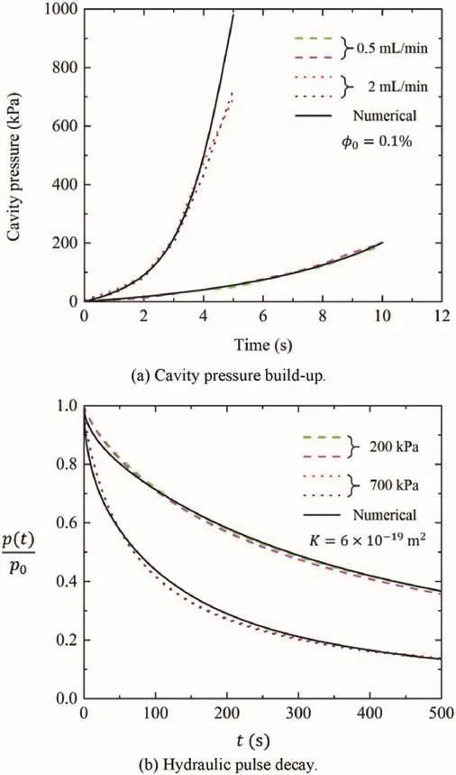
Fig.10.Numerical interpretation of transient test results.
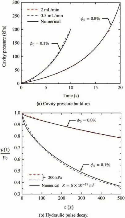
Fig.11.Experimental verification.
5.Discussion
In this study,the sealing experience suggests that the hydraulic pulses should be limited to a maximum value of 3 MPa to avoid epoxy delamination.For the proposed low-pressure transient pulse test,the interpretation of water permeabilitycan be complicated by the existence of trapped air within pressurized cavity.In the case of conventional transient permeability tests introduced by Brace et al.(1968),the hydraulic pulses may reach as high as 40 MPa.Since the compressibility of the air-water mixture under high pressure approaches that of pure water(see Fig.2),the influences of entrapped air bubbles on the decay pattern of cavity pressure can be neglected.This aspect can be demonstrated from the modeling results for cavity pressure decay(φ0=0.1%and 0.8%)with various initial hydraulic pulses,as shown in Fig.13a and b.It is obvious that the higher the initial pressure pulse is,the closer the decay curve approaches the theoretical decay pattern without entrapped air.And it requires a much greater level of pressure to overcome the air compressibility for a higher fraction of entrapped air.However,sealing may become a more critical problem for high-pressure hydraulic pulse test.Therefore,the compromise should be found between the sealing efficiency and air bubble compression.
Another important factor that may influence the selection of injection pressure is the risk of rock damage caused by the hydraulic pulses.In the experimental configuration of radial flow permeability test,the instantaneous pressurization induces tensile stress field around the cylindrical cavity.Microcracks can therefore be generated due to the low tensile strength of rock material.The opening of any discontinuities and defects may lead to the increase in rock permeability.Consequently,low-pressure hydraulic pulses(up to 1 MPa)have been chosen to eliminate any distinct stress effects on rock permeability.
For the numerical interpretation of transient pulse test,it is assumed that Cobourg limestone sample possesses isotropic permeability.However,the material stratification shows clear heterogeneous characteristic.Anisotropic permeability values of Cobourg limestone have been reported by NWMO(2007),who have measured one order of magnitude difference between the rock permeability values in directions normal and parallel to the nominal bedding plane.The proposed radial flow test is not designed to measure the anisotropic property of rock permeability.At the current laboratory scale of testing,the experimental results can only provide estimation of the average permeability of the Cobourg limestone.Future work should explore advanced methods for testing the permeability characteristic of heterogeneous rock.
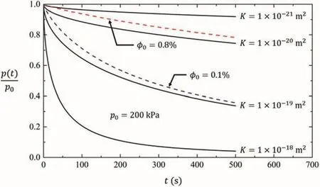
Fig.12.Hydraulic pulse decay matching without considering air bubble effects.
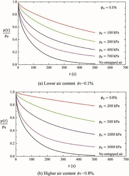
Fig.13.Influence of entrapped air bubbles on transient permeability test under different levels of hydraulic pulses.
6.Conclusions
This paper applies radial flow hydraulic pulse test to measure the permeability of saturated Cobourg limestone.The hydraulic pulse is generated within the central fluid-filled cavity of a hollow cylinder and then allowed to dissipate as pressurized fluid migrates into the rock matrix.The permeability of the rock can be interpreted according to the decay pattern of the cavity pressure.Finite difference method has been utilized to numerically simulate the transient diffusion of hydraulic pulse.
Despite great efforts to reduce air within the pressurization system,entrapped air bubbles cannot be completely removed from the central cavity.The proposed transient pulse tests have been conducted at pressure levels between 200 kPa and 700 kPa.Within this pressure range,the entrapped air bubbles can drastically increase the compressibility of the pressurized fluids.As a result,the hydraulic pulse will be relaxed by compression of the air bubbles,rather than diffusing through the saturated rock matrix.The decay of cavity pressure can be significantly delayed by the air bubble effects.
Due to the existence of entrapped air within pressurized cavity,the pressure build-up of air-water mixture during establishing hydraulic pulses will be considerably delayed and become highly nonlinear.The residual air fraction within cavity can be estimated based on the recorded cavity pressure build-up curves.Accounting for the influence of air inclusions on hydraulic pulse decay,the permeability of Cobourg limestone sample is estimated to be around 6×10-19m2.Without considering the pressure-dependent compressibility of air-water mixture,the rock permeability can be underestimated by one to two orders of magnitude depending on the air fraction.
Conflicts of interest
The author wishes to confirm that there are no known conflicts of interest associated with this publication and there has been no significant financial support for this work that could have influenced its outcome.
Acknowledgements
The testing facilities used in this research are provided by Environmental Geomechanics Laboratory at McGill University.The assistance of Mr.John Bartczak,technician of the Civil Engineering Laboratory,is gratefully acknowledged.The author also thanks summer student Stacy Larochelle for her help during the experiment.
Bernabé Y.The effective pressure law for permeability in Chelmsford granite and Barre granite.International Journal of Rock Mechanics and Mining Sciences&Geomechanics Abstracts 1986;23(3):267-75.
Brace WF,Walsh JB,Frangos WT.Permeability of granite under high pressure.Journal of Geophysical Research 1968;73(6):2225-36.
Bredehoeft JD,Papadopulos SS.A method for determining the hydraulic properties of tight formations.Water Resources Research 1980;16(1):233-8.
Carslaw HS,Jaeger JC.Conduction of heat in solids.2nd ed.Oxford:Oxford University Press;1959.
Chen YF,Hu SH,Wei K,Hu R,Zhou CB,Jing LR.Experimental characterization and micromechanical modeling of damage-induced permeability variation in Beishan granite.International Journal of Rock Mechanics and Mining Sciences 2014;71:64-76.
Cooper HH,Bredehoeft JD,Papadopulos IS.Response of a finite-diameter well to an instantaneous charge of water.Water Resources Research 1967;3(1):263-9.
Delage P,Cui YJ,Tang AM.Clays in radioactive waste disposal.Journal of Rock Mechanics and Geotechnical Engineering 2010;2(2):111-23.
Escoffier S,Homand F,Giraud A,Hoteit N,Su K.Under stress permeability determination ofthe Meuse/Haute-Marne mudstone.Engineering Geology 2005;81(3):329-40.
Fredlund DG.Density and compressibility characteristics of air-water mixtures.Canadian Geotechnical Journal 1976;13(4):386-96.
Keller CK,Kamp G.Slug tests with storage due to entrapped air.Groundwater 1992;30(1):2-7.
Neuzil CE,Cooley C,Silliman SE,Bredehoeft JD,Hsieh PA.A transient laboratory method for determining the hydraulic properties of ‘Tight’Rocks-II.Application.International Journal of Rock Mechanics and Mining Sciences&Geomechanics Abstracts 1981;18(3):253-8.
Nguyen TS,Selvadurai APS.Coupled thermal-mechanical-hydrological behaviour of sparsely fractured rock:implications for nuclear fuel waste disposal.International Journal of Rock Mechanics and Mining Sciences&Geomechanics Abstracts 1995;32(5):465-79.
NWMO(Nuclear Waste Management Organization).Evaluation of experimental protocols for characterizing diffusion in sedimentary rocks.NWMO TR-2007-11.Toronto ON:NWMO;2007.
NWMO(Nuclear Waste Management Organization).OPG’s deep geologic repository for low&intermediate level waste:Geosynthesis.NWMO DGR-TR-2011-11.Toronto ON:NWMO;2011.
Pan ZJ,Ma Y,Connell LD,Down DI,Camilleri M.Measuring anisotropic permeability using a cubic shale sample in a triaxial cell.Journal of Natural Gas Science and Engineering 2015;26:336-44.
Scherer GW.Dynamic pressurization method for measuring permeability and modulus:I.theory.Materials and Structures 2006;39(10):1041-57.
Scherer GW.Poromechanics analysis of aflow-through permeameter with entrapped air.Cement and Concrete Research 2008;38(3):368-78.
Schuurman IE.The compressibility of an air/water mixture and a theoretical relation between the air and water pressures.Géotechnique 1966;16(4):269-81.
Selvadurai APS,Carnaffan P.A transient pressure pulse method for the measurement of permeability of a cement grout.Canadian Journal of Civil Engineering 1997;24(3):489-502.
Selvadurai APS,Jenner L.Radial flow permeability testing of an argillaceous limestone.Groundwater 2013;51(1):100-7.
Siriwardane H,Haljasmaa I,McLendon R,Irdi G,Soong Y,Bromhal G.Influence of carbon dioxide on coal permeability determined by pressure transient methods.International Journal of Coal Geology 2009;77(1-2):109-18.
Siriwardane HJ,Gondle RK,Varre SB,Bromhal GS,Wilson TH.Geomechanical response of overburden caused by CO2injection into a depleted oil reservoir.Journal of Rock Mechanics and Geotechnical Engineering 2016;8(6):860-72.
Tomac I,Gutierrez M.Coupled hydro-thermo-mechanical modeling of hydraulic fracturing in quasi-brittle rocks using BPM-DEM.Journal of Rock Mechanics and Geotechnical Engineering 2017;9(1):92-104.
Wang HF,Anderson MP.Introduction to Groundwater Modeling:finite difference and finite element methods.San Diego,CA:Academic Press;1982.
Wang XR,Shao H,Hesser J,Zhang CL,Wang WQ,Kolditz O.Numerical analysis of thermal impact on hydro-mechanical properties of clay.Journal of Rock Mechanics and Geotechnical Engineering 2014;6(5):405-16.
White FM.Fluid mechanics.2nd ed.Boston,MA:McGraw-Hill;1986.
Zhang CL.The stress-strain-permeability behaviour of clay rock during damage and recompaction.Journal of Rock Mechanics and Geotechnical Engineering 2016;8(1):16-26.
Zhou CB,Chen YF,Jiang QH,Lu WB.A generalized multi-field coupling approach and its application to stability and deformation control of a high slope.Journal of Rock Mechanics and Geotechnical Engineering 2011;3(3):193-206.
 Journal of Rock Mechanics and Geotechnical Engineering2018年1期
- Journal of Rock Mechanics and Geotechnical Engineering的其它文章
- Anisotropy effect on strengths of metamorphic rocks
- Influence of loading and heating processes on elastic and geomechanical properties of eclogites and granulites
- Geomechanical characterization of volcanic rocks using empirical systems and data mining techniques
- Investigation of creep behaviours of gypsum specimens with flaws under different uniaxial loads
- Effects of lime addition on geotechnical properties of sedimentary soil in Curitiba,Brazil
- Corrigendum to“Back-analysing rock mass modulus from monitoring data of two tunnels in Sydney,Australia”[J Rock Mech Geotech Eng 5(2017)877-891]
