
Beam-pointing error compensation method of phased array radar seeker with phantom-bit technology
2017-11-20 01:56:27QiuqiuWENTinyuLUQunliXIAZedongSUN
CHINESE JOURNAL OF AERONAUTICS 2017年3期
Qiuqiu WEN,Tinyu LU,Qunli XIA,Zedong SUN
aSchool of Aerospace Engineering,Beijing Institute of Technology,Beijing 100081,China
bBeijing Aerospace Automatic Control Institute,Beijing 100854,China
cArmy Aviation Institute,Beijing 100041,China
Beam-pointing error compensation method of phased array radar seeker with phantom-bit technology
Qiuqiu WENa,*,Tianyu LUb,Qunli XIAa,Zedong SUNc
aSchool of Aerospace Engineering,Beijing Institute of Technology,Beijing 100081,China
bBeijing Aerospace Automatic Control Institute,Beijing 100854,China
cArmy Aviation Institute,Beijing 100041,China
Available online 8 May 2017
*Corresponding author.
E-mail address:wenqiuqiu82@bit.edu.cn(Q.WEN).
Peer review under responsibility of Editorial Committee of CJA.
Production and hosting by Elsevier
http://dx.doi.org/10.1016/j.cja.2017.03.020
1000-9361©2017 Chinese Society of Aeronautics and Astronautics.Production and hosting by Elsevier Ltd.
This is an open access article under the CC BY-NC-ND license(http://creativecommons.org/licenses/by-nc-nd/4.0/).
A phased array radar seeker(PARS)must be able to effectively decouple body motion and accurately extract the line-of-sight(LOS)rate for target missile tracking.In this study,the realtime two-channel beam pointing error(BPE)compensation method of PARS for LOS rate extraction is designed.The PARS discrete beam motion principium is analyzed,and the mathematical model of beam scanning control is finished.According to the principle of the antenna element shift phase,both the antenna element shift phase law and the causes of beam-pointing error under phantom-bit conditions are analyzed,and the effect of BPE caused by phantom-bit technology(PBT)on the extraction accuracy of the LOS rate is examined.A compensation method is given,which includes coordinate transforms,beam angle margin compensation,and detector dislocation angle calculation.When the method is used,the beam angle margin in the pitch and yaw directions is calculated to reduce the effect of the missile body disturbance and to improve LOS rate extraction precision by compensating for the detector dislocation angle.The simulation results validate the proposed method.
©2017 Chinese Society of Aeronautics and Astronautics.Production and hosting by Elsevier Ltd.This is an open access article under the CC BY-NC-ND license(http://creativecommons.org/licenses/by-nc-nd/4.0/).
Beam-pointing error;
Beam scanning control;
Line-of-sight rate extraction;
Phantom-bit technology;
Phased array radar seeker
1.Introduction
The phased array radar seeker(PARS)is a new type of guidance system with many advantages,such as rapidity,flexibility,high range,and strong anti-jamming capability,making it of interest for upgrading the homing guidance missile systems.1,2Different with traditional mechanical scanning radar seekers,PARS is strapped on the missile body and conducts beam scanning via the phase shift value of the elements radiating from the digital phase shifter.3But the beam granularity appears during the beam scanning process,causing the beam to scan discretely and reducing PARS beam scanning accuracy.4–6In order to control beam granularity,the phantombit technology(PBT)has been widely applied in PARS.Although the PBT can improve the PARS beam scanning accuracy,it also negatively affects the beam pointing error,which will lead to body movement incompletely decoupling when the beam pointing and inertial measurement unit information are used to extract the guidance information.7–9
Furthermore,as a target detection device,PARS should output the line-of-sight(LOS)rate for the guidance of a homing missile by using the proportional navigation law.10Obtaining of LOS of PARS is calculated from inertial measurements of missile attitude angle and beam angle.11The beam pointing error will lead to wrong LOS rate output,and then decrease guidance performance.Thereby,studying beam-pointing error caused by PBT is of important significance to calibration of PARS as well as stability and accuracy of guidance system.
In Refs.12,13,some scholars have studied problems caused by quantization error of PARS and corresponding solutions.But the above references only consider the lack of an initial antenna scanning angle,which prevents the array antenna elements within the sub-array from scanning.Moreover,in Ref.14,the problem caused by pointing error of strap-down phased array seeker applied in satellite communication was studied.However,there are few research studies on the guidance problem caused by PBT and related solution strategies.
Similar with PBT,the radome boresight error of PARS can also affect the output of LOS rate.It would induce a disturbance rejection rate that would result in a disturbance rejection rate parasitical loop in the guidance loop.In Refs.15,16,the effects of the radar seeker radome boresight error on the stability and guidance accuracy of homing missiles were investigated.In Refs.17,18,the effect of the disturbance rejection rate caused by spring torque and damping torque on the stability of the guidance system was analyzed.At the same time,Janice et al.2stated that radome boresight error is a key technique to be urgently solved for the terminal guidance of homing missiles.Peterson et al.19proposed a type of radome boresight error compensation method.The related results and methods are useful for this study.
The current study aims to present a real-time two-channel beam-pointing error compensation method for PARS LOS rate extraction.To this end,the PARS discrete beam motion principium is givenfirstly.According to the principle of the antenna element shift phase,the mathematical model of beam scanning control is built.Both the antenna element shift phase law and the causes of beam-pointing error under phantom-bit conditions are analyzed.Furthermore,the effect of BPE caused by PBT on the extraction accuracy of the LOS rate and stability margin of the guidance system is examined.Then,a two-channel LOS rate extraction model using a beampointing error compensation method,which includes coordinate transforms,beam angle margin compensation,and detector dislocation angle calculation,is proposed.Finally,results of numerical simulations for four conditions are presented,and the effectiveness of the compensation method is proved.
2.PARS beam control and beam-pointing error
2.1.Target tracking control and LOS rate output principle
The relative position relationship of the PARS beam,missile,and target in a portrait plane is shown in Fig.1.The missile center of mass is defined as pointO,the inertial space coordinate axis is defined asOxI,and the lengthwise axis of the missile is expressed asOxM.OxBis the PARS beam axis,andOxTis the direction to the target.In Fig.1,ϑ is the body attitude angle,qthe LOS angle,θ the angle between the LOS and the lengthwise axis of the missile,θBthe beam direction angle,and ε the detector dislocation angle.
The target tracking control loop diagram of PARS is shown in Fig.2.Here,˙qis the true LOS rate,˙ϑIMUthe angular velocity of the body measured by the inertial measurement unit(IMU)on the missile,kthe control gain,Gε(s)the dynamics of PARS’s monopulse angle measurement,GIMU(s) the dynamics of PARS’s angular rate of body measurement,andGθ(s)the beam control measurement.
According to Fig.3,the beam angle control command can be written as
where εsis the dislocation angle measured by PARS.
And the LOS rate output of PARS is
In this study,the dynamics of PARS’s monopulse angle measurement and IMU are assumed to be fast enough.Thereby,Eq.(2)is simplified viaGε(s)=GIMU(s)=1
Eq.(5)shows that the disturbance rejection rate caused by body movement will be zero when the beam controlGθ(s)equals one.If not,the body movement(˙ϑ)will be coupled into the LOS rate output of PARS.As a result,the performance of the PARS beam control becomes the key for decoupling body movement from the LOS rate.
2.2.PARS beam control
When the radiating element phase shift value of PARS is ΔφB,the element spacing isd,the radar wavelength is λ,and the angle(θB)of the beam-pointing deviation from the normal direction of the antenna is certain,which can be expressed as follows:
We can determine from Eq.(6)that the antenna direction changes with changing phase shift value,and ΔφBis obtained from the digital phase shifter.When the digit of the phase shifter isK(Kis a positive integer),the minimum phase shift value can be expressed as follows:
The radiating element phase shift value from the phase shifter is expressed as follows:
wherepis the beam control code,which is provided by the digital phase shifter,p=0,1,2,...,2K-1.Notice that ΔφBis discrete from Eq.(8),and then the beam movement is also discrete according to Eq.(6).As a result,PARS broadcasts electromagnetic waves based on the beam angle instruction(θBC),when a missile tracks a target.
Fig.3 shows the beam control principle diagram of PARS.We can obtain the ideal phase shift value
between the adjacent elements on the basis of the beam angle instruction(θBC).The beam control code(p)can be obtained by roundingThe phase shifter output practical phase shift value (ΔφB=pΔφBmin)between adjacent elements is obtained according top.The practical beam angle(θB)can be obtained by Eq.(3).
2.3.Phantom-bit technology
Beam granularity(θB(p+1)- θB(p))is determined by the bit of the phase shifter.A smaller bit leads to larger beam granularity.To reduce beam granularity and make the phased array antenna scanning approach the level of mechanical continuous scanning,the bit should be increased.With the cost and complexity considered,the PBT is widely applicable in practical engineering.With PBT,PARS could achieve performance approximate to that of a high-bit phase shifter by using a low-bit phase shifter.Fig.4 shows the principle architecture of the PBT phase shift.The control signal register and arithmetic unit correspond to a high-bit phase shift.The lowmbit binary codes of the arithmetic unit are eliminated during phase shifter setting,while high-bit binary codes are sent to the phase shifter to finish unit phase setting.3If the actual bit of the phase shifter isband the phantom bit ism,the phase control computer will calculate the minimum phase shift value(ΔφBmin=2π/2K)withK=b+mbits.The beam control codepis expressed by a binary figure in the control signal registerand arithmetic unit,and the theoretical phase shift code is expressed asZ=ipfor element No.i;with the lowm-bit eliminated,we setZ-mod (Z,2m)as the practical phase shift code,where mod (Z,2m)is the remainder whenZis divided by 2m.
This study used a missile diameter of 120 mm,and Ka waveband(8 mm wavelength)is used to meet the ratio of the element spacing to radar wavelengthd/λ=0.5.The number of antenna elementsNis usually 30,but we setNto 32 for convenience.The phase shifter adopts the PBT(b=5,m=4).Fig.5 shows the practical phase shift value with PBT when the beam control codepis from 1 to 2m(2mis one period).This shows that the number of the sub-array will increase as the beam control code increases,while the phase shift value is identical in every sub-array.
2.4.BPE and BPES
The variation law of the phase shift error when the beam control code changes fromp=1 top=2mwas analyzed by the end-off approach.3Fig.6 shows the results,and we can easily see that the phase shift errors are centered at the 8th phantombit jump in one period,presenting an anti-symmetric distribution pattern.
The phase shift error causes differences between virtual beam pointing and theoretical beam pointing.This indicates the positive correlation between the BPE distribution law and phase shift error distribution law.BPE distributions under different phantom bits(m=3,m=4 andm=5)but fixedN=32 andb=5 are shown in Fig.7.
From Fig.7,we can easily see that BPE changes periodically(2mis one period).It presents an anti-symmetric distribution centered on the central jump of the phantom-bit period.The BPE envelope line will increase with the increase of the beam control code and phantom bits,respectively.
If Δ denotes the angle between the theoretical beam angle(θBC)and practical beam angle(θB)in one phantom-bit period caused by the BPES,we have
Differentiation of Eq.(6)yields
whereRi= ∂Δ/∂θBCpresent the effects of BPES on the beam angle control andithe numbers of phantom bits,which correspond tom=3,4 and 5.In practical engineering applications,BPES can be eliminated via calibration technology;to lighten the calibration workload,usually every one phantom-bit period(ΔθBC=3.58°)is calibrated.As shown in Table 1,the maximum BPES can be expressed asR3≈ ±0.01,R4≈ ±0.03 andR5≈ ±0.05.
According to Eq.(10),Gθ(s)in Eqs.(3)–(5)can be expressed asGθ(s)=1+Ri.Then,the PARS’s LOS rate output is

Table 1 Variation of BPE with different phantom bits.
From Eq.(13),it can be found that the LOS rate outputcaused by the angular missile body is not equal to zero unlessRiis equal to zero.According to the Bode diagram of the LOS angle rate under different PBNs,presented in Fig.8,the disturbance of the missile body will lead to additional line-of-sight angle-rate output.The greater the virtual digit is,the larger the amplitude of the additional line-of-sight angle-rate output will be.However,the virtual digit hardly affects the phase characteristics.
2.5.Effect on guidance loop
To analyze the influence of BPES on the guidance loop,a closed guidance loop for a perfectly stabilized PARS,along with BPES interactions,is given in Fig.9.Here,a fourthorder binomial representation of the missile homing guidance,including afirst-order model for a noise filter and third-order model for the control system,is used.LetGε(s)=GIMU(s)=1,and the guidance transfer function is
whereeis the effective navigation ratio,Vcthe closing velocity,Vmthe flight speed of the missile,Tgthe guidance time constant,Tαthe time constant of the angle of attack,andamthe missile acceleration.
According to Table.1,|R|≪ 1,and then Eq.(12)can be simplified as
The guidance system characteristic equation is
The guidance system transfer function is stable only if the poles of Eq.(16)are in the left-half plane.If the normalization factors:
are used,Eq.(16)becomes
The coefficients of Eq.(17)are defined as
The Routh criterion guarantees stability of the guidance system transfer function if the coefficients of Eq.(18)are positive(B0,B1,...,B5> 0)and if the following additional quantities are positive:
where
The stability of the guidance system transfer function is determined numerically for all values of the ratioa nd the parameterand the results are plotted in Fig.10.Clearly,larger values of|lead to a smaller range of stability for,and small values ofgive the widest possible range of stability.Thereby,it is necessary to control BPES for a large stability margin.
3.Decoupling algorithm of two channels used in BPE compensation
3.1.BPE compensation principle
The above analysis shows that,whenRis equal to zero,the practical beam angle(θB)is equal to the beam angle instruction(θBC),and PARS tracking loop can decouple body movement completely.Due to the beam control link,which uses PBT,the practical beam angle(θB)is not equal to the beam angle instruction(θBC);then,body movement is coupled with the LOS rate output,and the disturbance rejection rate parasitic loop will be introduced into the guidance loop of the missile,which affects the target-tracking performance of the missile.Furthermore,Ris not constant,which will cause volatility of the detector dislocation angle.The key cause of the above phenomenon is thatRis not equal to zero.According to Fig.3,we design a compensation loop to eliminate the effect of the beam control link.Fig.11 shows the BPE compensation principle diagram.
In Fig.11,θBCis measurable,θBcan be obtained by beam control code,and thus BPE(Δ)can be calculated by θBCminus θBin real time.
The PARS tracking loop transfer function can be expressed based on the simplified model using BPE compensation.
A comparison of Eqs.(11)and(21)shows that the effect of the body movement can be eliminated completely after BPE compensation is used,and the beam volatility is also resolved.At the same time,the PARS tracking loop transfer function is described as a first-order process of the phase lag.
3.2.Beam angle margin calculation
For the relationship betweenSbandS^b,the beam angle margin of PARS is applied in the 3D space.Fig.12 shows the angle relationship betweenSbandS^b.The related coordinate system and the angle definition are given in Appendix A.
The beam angle instructions(θBCy,θBCz)can be obtained via the measurement value ofSbat timet,and the practical beam angle(θBy, θBz)can be obtained via the beam control model and the calibration technique.The unit vector inS^bis presumablya^b= [1,0,0]T,which can be projected toSbat timet,denoted asab.The transformational matrix about the coordinate system is denoted asC.The subscript indicates the transformational direction,for example,Cmbdenotes the transformational matrix fromSmtoSb.Thereafter,
C^bmandCmbare then substituted into Eq.(6).abis then obtained at timet.We suppose thatab=given that the maximum beam control error is 0.3°. Δθyand Δθzare small.Thus,Δθyand Δθzare expressed as follows:
3.3.Beam angle control commands
The PARS dislocation angle is the angular deviation between the beam-pointing coordinate systemxb-axis and LOS coordinate systemxl-axis in the pitch and yaw directions.Beampointing coordinate systems on theyb-axis andzb-axis are considered real-time rotation axes.The beam control model causes the beam-pointing center(oxb)to rotate at an angular rate(,)proportional to the actual detector dislocation angle(,).Given that LOS motion is a slow variable and beam scanning motion is a fast variable,the detector dislocation angle can be eventually eliminated by closed-loop tracking.Thus,fast tracking of the target is realized.
The rotation angular rate of the beam-pointing axis relative to the inertial space can be expressed as follows:
Beam motion in the inertial space is composed of two parts.One is the motion of the beam-pointing axis relative to the missile body,whereas the other is the motion of the missile body relative to the inertial space.Thus,the mathematical expression is as follows:
where ω is the rotation angular rate vector;the subscripts denote the coordinate system transformational relation,and the superscript denotes the vector projection coordinate system.For example,denotes the rotation angular rate projection of the beam-pointing axis relative to the inertial space in the beam-pointing coordinate system.
According to Eq.(24),the following is obtained by multiplying both sides by the coordinate transformational matrix(Cib):
whereCibdenotes the transformational matrix fromSitoSb.The equation can be rewritten as follows:
[ωx,ωy,ωz]Tdenotes the rotation angular rate projection of the missile body relative to the inertial space in the missile body coordinate system,which can be measured by the gyroscope rate on the body.In Eq.(17),
PARS only outputs the LOS rate in the pitch and yaw directions.Eq.(28)is equivalent to the following:
The beam rotation angular rate of the beam-pointing axis relative to the missile body can be calculated by Eq.(29):
On the basis of the integral operation,we can obtain the beam control instructions θBCyand θBCzin the pitch and yaw directions,respectively.
Fig.13 shows the LOS rate extraction model for the two channels by BPE compensation.The model includes the detector dislocation angle calculation model,beam angle margin calculation model,and discrete beam control model.Each parameter has been given in the previous model building.
4.Simulation analysis
In this section,the tracking performance of PARS is verified through various simulations.First,we considered the discrete beam control model(Fig.4)to test the results of BPT compensation at different disturbance frequencies of the missile.The actual bit of the digital phase shifter is set asb=5,the phantom bit is set asm=4,and the ratio of the element spacing to the radar wavelength isd/λ=0.5.The real detector dislocation angle can be calculated according to the model given in Appendix B.
The missile motion and LOS angle input are modeled with a sinusoidal signal:
Four processing conditions are used to simulate the LOS rate extraction performance of PARS when the disturbance frequency of the missile is set asfm=2 Hz,which are shown in Figs.14–17.The forward path detector gain is set ask=10.The actual LOS rate input is projected to the beampointing coordinate system,and the LOS rate outputs from the LOS rate extraction model for the two channels are compared.Thereafter,the decoupling effect is analyzed.In the simulation,the decoupling effect can be expressed with the decoupling coefficients(η)as follows:
Processing condition 1:Without considering noise input
Fig.14(a)and(b)show the LOS rate comparison diagram in the pitch and yaw directions by only considering the beampointing error.
Processing condition 2:Considering noise input
Based on Condition 1,the variance is 0.012 by adding the zero mean WGN noise at the beam-pointing angle output point.Fig.15(a)and(b)show the LOS rate comparison diagram in the pitch and yaw directions by considering the noise input.
Processing condition 3:Adopting a low-pass filter
A low-pass filter is added at the LOS rate extraction point.Fig.16(a)and(b)show that the LOS rate comparison diagram in the pitch and yaw directions adopts the low-pass filter.Processing condition 4:Use of beam-pointing angle error compensation

Table 2 Maximum error estimation value of LOS rate and decoupling factor for four conditions.
Fig.17(a)and(b)show the LOS rate comparison diagram in the pitch and yaw directions with beam-pointing angle error compensation.
Fig.14 illustrates that the LOS rate extraction value presents a fluctuation phenomenon because of the beampointing error in the beam control process.It can be found from Fig.15 that discrete beam scanning results in beampointing angle error and causes a PARS disturbance rejection rate parasitical effect,which leads to severe noise amplification and severe LOS rate output fluctuations.Although the LOS rate performance is improved when the low-pass filter process is adopted(Fig.16),fluctuations still exist.From Fig.17,the LOS rate performance is significantly improved with the beam-pointing angle error compensation method.The estimated LOS rate follows the actual LOS rate input value smoothly and accurately.Table 2 shows the maximum error estimation value of the LOS rate and the decoupling factor for the four conditions at different disturbance frequencies of the missile;they-axis andz-axis express the pitch and yaw directions,respectively,the maximum error estimation value of the LOS rate in Condition 4 is lower than that in Conditions 1,2,and 3,and the decoupling factor is small in Condition 4.The beam-pointing error compensation can effectively isolate the body motion and accurately extract the LOS rate.At the same time,the larger the disturbance frequency of the missile is,the larger the decoupling factor is.
The effects of PBT on the LOS rate and LOS angle outputs are shown in Table 3;the phantom bitmis set to 2,3,4 and 5,and the forward path gaink=10.From the simulation results,we can easily see that the largermis,the larger the LOS angle tracking error and LOS rate estimation error are.
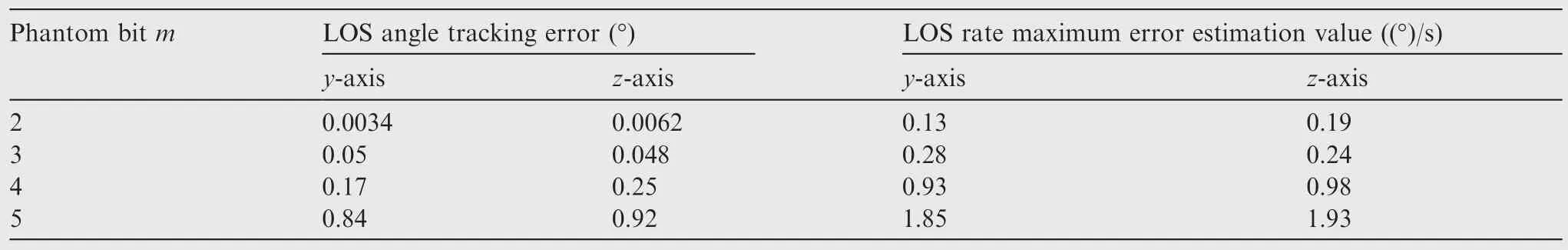
Table 3 Error change situation with different values of m.

Table 4 Error change situation with different values of k.
Second,we use the beam control model(Fig.14)to simulate the effects of the forward path detector gain(k)on the LOS rate and LOS angle outputs.The forward path gainkandRiare set to 20 and 0,respectively.The simulation results of Figs.18 and 19 show that the LOS angle tracking errors are close to 0.15°and 0.1°in the yaw and pitch directions,respectively.The LOS rate estimation error reaches 0.063(°)/s and 0.85(°)/s in the yaw and pitch directions,respectively.From Table 4,we can note that the largerkis,the smaller the error is.One reason is that the largerkcan reduce the delay time,increasing the tracking loop rapidly.
5.Conclusions
(1)The difference between the theoretical phase shift value and virtual phase shift value with PBT will lead to beampointing error,which is related to the number of phantom bits.The greatermis,the greater the beampointing error envelope is.The beam-pointing error increases with the beam scan angle and then causes BPES.As a result,body movements are coupled to the LOS rate output,which affects the accuracy of the LOS rate and stability margin of the guidance system.
(2)A two-channel decoupling algorithm and an LOS rate extraction model with the BPE compensation method for PARS are proposed.The beam angle margin in the pitch and yaw directions was calculated to reduce the effect of the missile body disturbance and to improve LOS rate extraction precision by compensating for the detector dislocation angle.The simulation results show that the LOS rate maximum error estimation value in Condition 4 is considerably lower than that in Conditions 1,2 and 3.The decoupling factor is considerably smaller in Condition 4.BPE compensation could effectively isolate the body motion,and the LOS rate could be extracted accurately.
(3)The larger the phantom bit(m)is,the larger the LOS angle tracking error and LOS rate estimation error are.At the same time,the forward path detector gain(k)also affects the tracking performance of PARS;the larger k is,the smaller the error is.In summary,use of the proposed BPE compensation method could improve the LOS rate extraction precision,thereby enhancing the missile guidance precision.
Appendix A
The coordinate systems used in this study are defined as follows:
(1)Inertial coordinate system(Si)Oxiyizi
Thexi-axis points to random direction,and theyi-axis points along the vertical direction.Thezi-axis direction can be obtained by the right-hand rule.
(2)Missile body coordinate system(Sm)Oxmymzm
Thexm-axis coincides with the lengthwise axis of the missile and points to the front of the missile.Theym-axis is located within the missile longitudinal symmetry plane and is perpendicular to thexm-axis.Thezm-axis direction can be obtained by the right-hand rule.
(3)LOS coordinate system(Sl)Oxlylzl
Thexl-axis points to the target.Theyl-axis is located within the vertical plane that contains thexl-axis and is perpendicular to thexl-axis.Thezl-axis direction can be obtained by the right-hand rule.
(4)Beam-pointing coordinate system(Sb)Oxbybzb
Thexb-axis points to the beam center axis.Theyb-axis is located within the plane that contains thexb-axis and is perpendicular toOxmzmplane.Theymaxis is perpendicular toxm.Thezb-axis direction can be obtained by the right-hand rule.
(5)Virtual beam-pointing coordinate system(S^b)Ox^by^bz^b
Thex^b-axis points to the direction defined by beam angle instruction.They^b-axis is located within the plane that contains thex^b-axis and is perpendicular to theOxmzmplane.They^b-axis is perpendicular tox^b.z^b-axis direction can be obtained with the right-hand rule.
(6)Measurement coordinate system(Sc)Oxcyczc
Thexc-axis points to the target.Theyc-axis is located within the plane that contains thexc-axis and is also perpendicular to theOxbzbplane.yc-axis is perpendicular toxc.Thezcaxis direction can be obtained by the right-hand rule.
According to the definition of coordinates,Fig.A1 shows the coordinate transform relationship.
In Fig.A1,ψ,ϑ and γ denote the missile body yaw angle,pitch angle and roll angle,respectively,withSias a benchmark;qsyandqszare the LOS angles in the yaw and pitch directions,respectively,withSias a benchmark;θBCyand θBCzare the beam-pointing angles in the yaw and pitch directions,respectively,withSbas a benchmark;εsyand εszare the seeker detector dislocation angles in the yaw and pitch directions,respectively,withSbas a benchmark;Δθyand Δθzare the angle deviations fromSbtoS^bin the yaw and pitch directions,respectively,withS^bas a benchmark;^εyand^εzare the angle deviations fromSltoS^bin the yaw and pitch directions,respectively,withS^bas a benchmark.
Appendix B
Fig.B1 shows the geometric relationship for practical detector dislocation angle calculation.The unit vector is supposedlya^b= [1,0,0]Tin the LOS coordinate system,which can be projected toS^band is denoted as [xsb,ysb,zsb]T.
The detector dislocation angle calculation formula is expressed as follows:
The PARS output is obtained by the beam-pointing angle error compensation,which can be expressed as follows:
1.Fan HT,Yang J,Zhu XP.Research on beam stabilization technology of phased array radar seeker.Acta Aeronaut Astronaut Sinica2013;34(2):387–92[Chinese].
2.Janice CR,James HM,Joel PB,Hudson T.The past,present,and future of electronically-steerable phased arrays in defense applications.Proceedings of aerospace conference;2008 Mar 1–8;2008.p.1–7.
3.Mailloux RJ.Phased array antenna handbook.2nd ed.Boston:Artech House;2005.
4.Garrod A.Digital modules for phased array radar.IEEE international symposium on phased array systems and technology;1996 Oct 15–18;1996.p.81–6.
5.Hord WE,Boyd CR,Diaz D.A new type of fast switching dualmode ferrite phase shifter.IEEE Trans Microwave Theory Tech1988;35(12):985–8.
6.Davis ME.Integrated diode phase-shifter elements for an X-band phased-array antenna.IEEE Trans Microwave Theory Tech1975;23(12):1080–4.
7.Jang SA,Ryoo CK,Choi K,Tahk MJ.Guidance algorithms for tactical missiles with strapdown seeker.SICE annual conference;2008 Aug 20–22;2008.p.2616–9.
8.Savage PG.Strapdown sculling algorithm design for sensor dynamic amplitude and phase-shift error.J Guid Control Dyn2012;35(6):1718–29.
9.Lu TY,Wen QQ,Yin J.The effect of phantom-bit technology on the performance of phased array seeker detection in the case of the initial beam angle.Optik-Int J Light Electron Opt2016;127(20):9996–10003.
10.Zarchan P.Tacticalandstrategicmissileguidance. 6th ed.Reston:American Institute of Aeronauticsamp;Astronautics;1990.p.555.
11.Du X,Xia QL.The research of guidance performance of the phased array seeker with platform for air-to-air missile.Optik-Int J Light Electron Opt2016;127(22):10322–34.
12.Song J,Wang J,Peng K,Pan C,Yang Z.Quantization error reduction for the phased array with 2-bit phase shifter.Wirel Personal Commun2010;52(1):29–41.
13.Smith MS,Guo YC.A comparison of methods for randomizing phase quantization errors in phased arrays.IEEE Trans Anten Propag1983;31(6):821–8.
14.Guan BR,Chen XH.A phased-array antenna for terrestrial satellite communication based on vitual phase shifting.J Microwaves2011;27(4):45–8[Chinese].
15.Nesline FW,Zarchan P.Radome induced miss distance in aerodynamically controlled homing missiles.17th fluid dynamics,plasma dynamics,and lasers conference;1984.p.99–115.
16.Du YL,Xia QL,Cai CT.Study on miss-distance of radar seeker guided missile due to radome slope error.J Project Rock Missiles Guidance2010;30(5):79–82[Chinese].
17.Song T,Lin DF,Wang J.Influence of seeker disturbance rejection rate on missile guidance system.J Harbin Eng Univ2013;34(10):1234–41[Chinese].
18.Li FG,Xia QL,Qi ZK,Sun J.Effect of parasitic loop on strapdown seeker and compensated with identification method.Syst Eng Electron2013;35(8):1717–22[Chinese].
19.Peterson D,Otto J,Douglas K.Radome boresight error and compensation techniques for electronically scanned arrays.Annual interceptor technology conference;1993.
29 June 2016;revised 8 October 2016;accepted 21 December 2016
 CHINESE JOURNAL OF AERONAUTICS2017年3期
- CHINESE JOURNAL OF AERONAUTICS的其它文章
- Improving the process forming limit considering forming defects in the transitional region in local loading forming of Ti-alloy rib-web components
- Residual stress determination in friction stir butt welded joints using a digital image correlation-aided slitting technique
- A cost driven predictive maintenance policy for structural airframe maintenance
- Analysis of the current density characteristics in through-mask electrochemical micromachining(TMEMM)for fabrication of micro-hole arrays on invar alloy film
- Estimation of ballistic coefficients of space debris using the ratios between different objects
- A rapid compensation method for launch data of long-range rockets under influence of the Earth’s disturbing gravity field