
Multiaxial fatigue life prediction of composite materials
2017-11-20 01:55JingmengWENGWeidongWENHongjianZHANG
CHINESE JOURNAL OF AERONAUTICS 2017年3期
Jingmeng WENG,Weidong WEN,Hongjian ZHANG
aJiangsu Province Key Laboratory of Aerospace Power System,Nanjing 210016,China
bState Key Laboratory of Mechanics and Control of Mechanical Structures,Nanjing 210016,China
cCollege of Energy and Power Engineering,Nanjing University of Aeronautics and Astronautics,Nanjing 210016,China
Multiaxial fatigue life prediction of composite materials
Jingmeng WENG,Weidong WEN*,Hongjian ZHANG
aJiangsu Province Key Laboratory of Aerospace Power System,Nanjing 210016,China
bState Key Laboratory of Mechanics and Control of Mechanical Structures,Nanjing 210016,China
cCollege of Energy and Power Engineering,Nanjing University of Aeronautics and Astronautics,Nanjing 210016,China
*Corresponding author.
E-mail address:gswwd@nuaa.edu.cn(W.WEN).
Peer review under responsibility of Editorial Committee of CJA.
Production and hosting by Elsevier
http://dx.doi.org/10.1016/j.cja.2017.03.019
1000-9361©2017 Production and hosting by Elsevier Ltd.on behalf of Chinese Society of Aeronautics and Astronautics.
This is an open access article under the CC BY-NC-ND license(http://creativecommons.org/licenses/by-nc-nd/4.0/).
In order to analyze the stress and strain fields in the fibers and the matrix in composite materials,a fiber-scale unit cell model is established and the corresponding periodical boundary conditions are introduced.Assuming matrix cracking as the failure mode of composite materials,an energy-based fatigue damage parameter and a multiaxial fatigue life prediction method are established.This method only needs the material properties of the fibers and the matrix to be known.After the relationship between the fatigue damage parameter and the fatigue life under any arbitrary test condition is established,the multiaxial fatigue life under any other load condition can be predicted.The proposed method has been verified using two different kinds of load forms.One is unidirectional laminates subjected to cyclic off-axis loading,and the other is f i lament wound composites subjected to cyclic tension-torsion loading.The fatigue lives predicted using the proposed model are in good agreements with the experimental results for both kinds of load forms.
©2017 Production and hosting by Elsevier Ltd.on behalf of Chinese Society of Aeronautics and Astronautics.This is an open access article under the CC BY-NC-ND license(http://creativecommons.org/licenses/by-nc-nd/4.0/).
Fatigue damage parameter;
Finite element analysis;
Life prediction;
Multiaxial fatigue;
Periodical boundary
condition
1.Introduction
Due to their high specific strength and high specific stiffness,composite materials have been widely used in many industrial fields,especially in aeronautical and astronautical structures.Taking aircraft engines as examples,some major components fail under multiaxial fatigue loading.Since composite structural components may be subjected to different forms of multiaxial cyclic loading,the task of predicting the multiaixal fatigue lives of structures becomes essential and indispensable.1
Multiaxial fatigue of composite materials can be divided into Multiaxial Stress fatigue under Uniaxial Loading(MSUL)and Multiaxial Stress fatigue under Multiaxial Loading(MSML).The multiaxial stress state of MSUL is caused by anisotropy of composite materials,so the ratio of biaxial stress is unchangeable.The multiaxial stress state of MSML is caused by both anisotropy of composite materials and multiaxial loading,so the ratio of biaxial stress can be changed according to external loading.
The fatigue behavior of composite materials under MSUL has been studied in depth.Theoretical research approaches involveS-Nequation,2models based on residual strength/stiffness,3,4and models based on progressive failure mechanisms.5–7Under MSML,these theoretical approaches are not suitable because there are numerous combinations of stress components.
For metallic materials,fatigue crack growth is a decohesion process along the shear bands of a crack tip.The normal strain on the crack plane accelerates this de-cohesion process.8Based on this fatigue damage mechanism,some researchers have proposed different critical plane approaches,such as Findley,9Fatemi,10Smith,11and Shang12,13et al.A good correlation with test data has been obtained for different materials and loading conditions.Since a critical plane approach reflects the mechanism of multiaxial fatigue damage,Petermann14and Plumtree15et al.introduced a critical plane concept into their studies of unidirectional laminates which were subjected to cyclic off-axis fatigue loading.This approach only needs the material properties of fibers and the matrix along with one curve between the fatigue damage parameter and the fatigue life to be known.Therefore,it’s very convenient for applications in engineering.
At the mesoscopic level,composite materials consist of fibers and matrix.For simplicity,fibers are always assumed to be distributed periodically in composite materials.Through applying corresponding periodical boundary conditions on an appropriate unit cell,the stress and strain fields in the fibers and the matrix can be analyzed.16–18
The objective of this paper is to propose a model for predicting the multiaxial fatigue lives of composite materials which have failed with matrix cracking.The fiber-scale unit cell model is used to calculate the stress and strain fields in the fibers and the matrix.With a newly proposed energy-based fatigue damage parameter,the model can be used to predict the fatigue lives of MSUL and MSML.
2.Method of fatigue life prediction
2.1.Energy-based fatigue damage parameter
The fracture plane of a unidirectional laminate is parallel to the fibers when being subjected to cyclic off-axis loading.With the fracture plane as the critical plane,the critical plane concept was used to deal with the problem of multiaxial fatigue life prediction by Petermann14and Plumtree15et al.Their fatigue damage parameters are defined as Eqs.(1)and(2),respectively.
whereRis the ratio of minimum-to-maximum load,σ22and τ12are the normal stress and shear stress on the critical plane,respectively,ε22and γ12are the normal strain and shear strain on the critical plane,respectively,and Δε22and Δγ12are the tensile strain range and shear strain range on the critical plane,respectively.
From the perspective of fracture mechanics,there are three basic forms of crack propagation as shown in Fig.1.For composite materials which have failed with matrix cracking,these three forms of crack propagation are taken into consideration in this paper,and the relevant stress and strain components in the matrix are used to establish a new energy-based fatigue damage parameter in the following part.
Under complex cyclic loading,the stress in the transverse direction of the matrix is not all positive everywhere.Since compressive stress will close the crack and block the propagation of the crack,the damage parameter in the transverse direction of the matrix is given by Eq.(3).
whereu(x)is the unit step function:u(x)=1 whenx>0;u(x)=0 whenx<0.
Since positive and negative shear stress has the same effect on crack propagation,the damage parameter corresponding to shear stress is given by Eqs.(4)and(5).
where sgn(x)is the sign function:sgn(x)=1 whenx>0;sgn(x)=-1 whenx<0.
The experimental results of unidirectional laminates show that theS–Ncurve in each material principal direction is not coincident with each other,i.e.,each stress component has a different contribution to fatigue damage.
Based on the above analysis,the energy-based fatigue damage parameter of the matrix is defined as
whereVmis the volume of the matrix,Yis the static tensile strength in the transverse direction,andSis the static shear strength in the material principal plane.
When a fiber-scale unit cell is used to analyze the stress and strain fields at the mesoscopic level,the energy-based fatigue damage parameterW*can be extended as Eq.(7)based on the volume average method.
whereNmis the number of matrix elements,Viis the volume of theith matrix element,andVis the volume of the whole unit cell.
When the critical plane approach is used to predict the fatigue lives of composite laminates,the laminates are usually simplified to a two-dimensional model.In addition,the stress/strain component used in the fatigue damage parameter is the average value in the matrix.However,the stress and strain fields in the matrix are not uniform,so the average value cannot reflects the influence of stress/strain on fatigue damage exactly.By using Eq.(7),the contributions of stress and strain components on fatigue damage can be reflected more accurately.
2.2.Numerical stress/strain analysis
2.2.1.Stress in each material principle direction
At present,experimental studies in the aspect of multiaxial fatigue can be classified into two types,i.e.,unidirectional laminates subjected to off-axis uniaxial tension-tension loading and composite materials subjected to tension-torsion loading.No matter which one is adopted,an external load should be transformed into the material coordinate system when predicting the fatigue lives of composite materials.For tensiontorsion loading in Fig.2,the relationship between the global coordinate system and the material coordinate system can be expressed as
whereTis the coordinate transformation matrix,and its specifi c expression is
2.2.2.Geometric model of unit cell
It is always assumed that fibers are distributed periodically in matrix.The most common distribution forms are square diagonal arrangement,square arrangement,and hexagon arrangement,as shown in Fig.3.For the convenience of finite element modeling,square arrangement is adopted in this paper.
2.2.3.Finite element model of unit cell
Prior to analysis,some basic assumptions are made as below:
(1)The bonding between a fiber and the matrix is so good that they won’t separate from each other until failure.
(2)The porosity of composite materials is small enough to be ignored.
(3)The fibers and the matrix are in an elastic state during the whole process.
Based on ANSYS system,the unit cell is meshed by 3D solid elements in this paper(see Fig.4,the cylinder in the center of the unit cell represents a fiber,and the rest represents the matrix).Moreover,periodic boundary conditions are accomplished through the nodal displacement constraint equations in ANSYS.Therefore,the same meshing of each opposite area of the unit cell is produced here.
2.2.4.Periodic boundary condition
Xia et al.16proposed an explicit unif i ed form of boundary conditions for a periodic Representative Volume Element(RVE).It can be expressed as
For a fi ber-scale unit cell model which is subjected to inplane multiaixal fatigue loading(see Fig.5),Eq.(10)can be speci fi ed as below.
whereu,v,andware displacement components alongx,y,andzaxes,respectively,xxis the distance from FaceABFEto FaceDCGH,zzis the distance from FaceBCGFto FaceADHE.
(2)Constraint equations of lines
Under in-plane multiaxial stress,the node on every edge of FaceEFGHhas the same displacement as the corresponding node on FaceABCDin theOxyplane.Therefore,the constraint equations of nodes on these edges are included in the constraint equations of the corresponding surfaces.Eqs.(14)–(16)give the constraint equations of the rest lines.
LineEAand LineHD
(3)Constraint equations of corner nodes
All Degrees of Freedom(DoFs)of NodeDare constrained,and the constraint equations of other corner nodes are included in the corresponding lines.

Table 1 Mechanical properties of glass fiber and matrix.
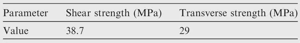
Table 2 Mechanical properties of E-glass/ERL 2256.
When analyzing the stress and strain fields in the unit cell model,the equivalent load in each material principle direction is calculated by the volume average method(Eq.(18)).In order to make a difference between the equivalent load and the external load within a certain error range,dichotomy is used to adjust the given deformation in each material principle direction.whereNis the number of whole elements,σijkis the stress of thekth element in directionij,Vkis the volume of thekth element,andVis the volume of the whole unit cell.
2.3.Method of multiaxial fatigue life prediction
Fig.6 shows the procedures of predicting multiaxial fatigue life in detail.According to these specific procedures,the fatigue life of MSUL or MSML can be predicted.
In addition,Refs.14,15,19have shown that all data fall on a straight line when the fatigue damage parameter is plotted against the experimental fatigue life in a lg-lg coordinate system.This relationship will be verified and used in this paper.
3.Experimental verification
Two sets of test data are used to verify the proposed multiaxial fatigue life prediction method.One is the data of unidirectional laminates subjected to cyclic off-axis loading,7and the other is the data of f i lament wound composites subjected to cyclic tension-torsion loading.20
3.1.Off-axis loading(MSUL)
The fatigue lives of unidirectional E-glass fiber reinforced epoxy laminates at six different fiber load angles have been tested by Hashin and Rotem.7The ratio of minimum-tomaximum load is 0.1,and the fiber volume fraction is 60%.The material properties of constituents and E-glass/ERL 2256 are listed in Tables 1 and 2,respectively.
The original six series of test data are plotted in Fig.7,in which σmaxis the maximum stress.It can be seen that fatigue lives are strongly influenced by the fiber load angle α.
For all fiber load angles,the failure mode is matrix cracking parallel to the fiber direction.Therefore,the proposed method in Section 2 is applicable.
After analyzing the stress and strain fields in the unit cell models under all loading conditions in Fig.7,the calculated fatigue damage parameters are plotted against the fatigue lives in a lg-lg coordinate system as shown in Fig.8.If ignoring the scatter,allW*–Ndata fall on a straight line,and this straight line is fitted by the least square method as follows:
To establish theW*–Ncurve,any arbitrary set of data can be used as the data of a reference loading condition.In order to verify the applicability of the proposed method,consistent with Ref.14,data obtained from α =20°are used to establish theW*–N curve(see Fig.9).With the least square method,the linear relationship between lgW*and lgNcan be fitted as

Table 3 Mechanical properties of glass fiber and matrix.

Table 4 Mechanical properties of glass/E-51.
Using theW*–N curve of α =20°as a reference,the comparisons between the predicted fatigue lives and the experimental results for the other loading conditions are presented in Fig.10.With the same test data,Figs.11and 12 present the comparisons between the experimental results and the fatigue lives predicted using the critical plane approaches by Petermann14and Plumtree15et al.,respectively.
Plumtree’s prediction is made using theW*–Ncurve of α=15°as a reference.In Fig.12,it is obvious that the pre-dicted fatigue lives of α =5°,10°,and 20°are much longer than the experimental results.
The fatigue lives predicted using the proposed method and Petermann’s critical plane method14are plotted against the experimental lives with a lg-lg coordinate system as shown in Fig.13.From Figs.13(b)–(e),the accuracies of these two predictions at α =10°,15°,30°,and 60°are almost the same.From Fig.13(a),only 20%data of Petermann’s prediction lie within the five-error band,and 80%data of the present prediction lie within the five-error band.Obviously,the fatigue lives predicted using the proposed method are much closer to the test data.
3.2.Tension-torsion loading(MSML)
The fatigue lives of f i lament wound composites at three different winding angles,namely φ =35°,55°,and 70°,have been tested by Qi and Cheng.20The fiber volume fraction is 55%,the ratio of minimum-to-maximum load is 0,and the ratio of tension-to-torsion load is 0.5.The material properties of constituents and E-glass/E-51 are listed in Tables 3 and 4,respectively.
Even though the direction of fibers will deflect a small angle in the cross region,at the mesoscopic level,the±φ f i lament wound composites can also be treated as±α laminates.19Therefore,the proposed method in Section 2 is also applicable.
The original three series of test data are plotted in Fig.14.It can be seen that fatigue lives are strongly influenced by the fiber winding angle.
For all winding angles,the failure mode is matrix cracking parallel to the fiber direction.Hence,the proposed method in Section 2 can be applied.
After analyzing the stress and strain fields in the unit cell models of all loading conditions in Fig.14,the calculated fatigue damage parameters are plotted against the fatigue lives in a lg-lg coordinate system as shown in Fig.15.If ignoring the scatter,allW*–Ndata fall on a straight line,and this straight line is fitted by the least square method as follows:
To establish theW*–N curve,any arbitrary set of data can be used as the data of a reference loading condition.Data obtained from φ =55°are used to establish theW*–Ncurve(see Fig.16).With the least square method,the linear relationship between lgW*and lgNcan be fitted as
With theW*–Ncurve of φ =55°as a reference,the comparisons between the predicted fatigue lives and experimental results are presented in Fig.17.The predicted fatigue lives are also plotted against the average experimental lives in a lg-lg coordinate system as shown in Fig.18.The predicted results and the test data show very good agreements,and 79%data of the total predictions lie within the three-error band.
4.Conclusions
(1)A method of predicting the multiaxial fatigue lives of composite materials is developed in this paper.The stress and strain fields in the matrix are analyzed through a fiber-scale unit cell model.Together with the proposed energy-based fatigue damage parameter,the method of predicting multiaxial fatigue life has been developed.Once the relationship between the fatigue damage parameter and the fatigue life is established with any arbitrary test condition,the fatigue life under any other load condition can be predicted.Therefore,this proposed method is a potentially valuable tool for multiaxial fatigue design.
(2)The proposed method has been applied to predict the fatigue lives of unidirectional laminates subjected to cyclic off-axis loading(MSUL)and those of f i lament wound composite materials subjected to cyclic tensiontorsion loading(MSML).The predicted results show good agreements with the test data.
Acknowledgements
The authors appreciate the supports from the Jiangsu Province Key Laboratory of Aerospace Power System of China(No.NJ20140019)and the National Natural Science Foundation of China(No.51205190).
1.Sun G,Shang D.Prediction of fatigue lifetime under multiaxial cyclic loading using finite element analysis.Mater Des2010;31(1):126–33.
2.Tate JS,Kelkar AD.Stiffness degradation model for biaxial braided composites under fatigue loading.Compos Part B Eng2008;39(3):548–55.
3.Lian W,Yao W.Fatigue life prediction of composite laminates by FEA simulation method.Int J Fatigue2010;32(1):123–33.
4.Wicaksono S,Chai GB.Life prediction of woven CFRP structure subject to static and fatigue loading.ComposStruct2015;119:185–94.
5.Shokrieh MM,Lessard LB.Multiaxial fatigue behaviour of unidirectional plies based on uniaxial fatigue experiments—I.Modelling.Int.J.Fatigue1997;19(3):201–7.
6.Shokrieh MM,Lessard LB.Multiaxial fatigue behaviour of unidirectional plies based on uniaxial fatigue experiments—II.Experimental evaluation.Int J Fatigue1997;19(3):209–17.
7.Hashin Z,Rotem A.A fatigue failure criterion for fiber reinforced materials.J Compos Mater1973;7:448–64.
8.Shang D,Sun G,Yan C,Chen J,Cai N.Creep-fatigue life prediction under fully-reversed multiaxial loading at high temperatures.Int J Fatigue2007;29(4):705–12.
9.Findley WN.Fatigue of metals under combinations of stresses.Trans ASME1957;79:1337–48.
10.Fatemi A,Socie DF.A critical plane approach to multiaxial fatigue damage including out-of-phase loading.Fatigue Fract Eng Mater Struct1988;11(3):149–65.
11.Smith K,Watson P,Topper T.A stress-strain function for the fatigue of metals.J Mater1970;5(4):767–78.
12.Shang DG,Wang DJ.A new multiaxial fatigue damage model based on the critical plane approach.Int J Fatigue1998;20(3):241–5.
13.Shang D,Sun G,Deng J,Yan C.Multiaxial fatigue damage parameter and life prediction for medium-carbon steel based on the critical plane approach.Int J Fatigue2007;29(12):2200–7.
14.Petermann J,Plumtree A.A unif i ed fatigue failure criterion for unidirectional laminates.Compos Part A Appl Sci Manuf2001;32(1):107–18.
15.Plumtree A,Cheng GX.A fatigue damage parameter for off-axis unidirectional f i bre-reinforced composites.Int J Fatigue1999;21(8):849–56.
16.Xia Z,Zhang Y,Ellyin F.A unif i ed periodical boundary conditions for representative volume elements of composites and applications.Int J Solids Struct2003;40(8):1907–21.
17.Xu K.A numerical study on the progressive failure of 3D fourdirectional braided composites.AdvMaterSciEng2013;2013:513724-1–513724-14.
18.Li N,Chen PH,Liu XY,Ma W,Wang XC.A micro-macro finite element model for failure prediction of ComeldTMjoints.Compos Sci Technol2015;117:334–41.
19.Qi D,Cheng G.Failure analysis of fiber-reinforced composites under multiaxial cyclic stress.Polym Compos2008;29(8):922–31.
20.Qi DT,Cheng GX.Fatigue behavior of f i lament-wound glass fiber reinforced epoxy composite tubes under tension/torsion biaxial loading.Polym Compos2007;28(1):116–23.
18 May 2016;revised 19 August 2016;accepted 21 September 2016 Available online 8 May 2017
 CHINESE JOURNAL OF AERONAUTICS2017年3期
- CHINESE JOURNAL OF AERONAUTICS的其它文章
- Review on signal-by-wire and power-by-wire actuation for more electric aircraft
- Real-time solution of nonlinear potential flow equations for lifting rotors
- Suggestion for aircraft flying qualities requirements of a short-range air combat mission
- A high-order model of rotating stall in axial compressors with inlet distortion
- Experimental and numerical study of tip injection in a subsonic axial flow compressor
- Dynamic behavior of aero-engine rotor with fusing design suffering blade of f