Research on adaptive anti-rollover control of kiloton bridge transporting and laying vehicles①
Guo Rui(郭 锐), Shi Yu, Wang Chao, Tian Yaya, Zhao Jingyi
(*Hebei Provincial Key Laboratory of Heavy Machinery Fluid Power Transmission and Control, Yanshan University, Key Laboratory of Advanced Forging & Stamping Technology and Science (Yanshan University), College of Mechanical Engineering, Yanshan University, Qinhuangdao 066004, P.R.China) (**Lianyungang Tianming Equipment Co., Ltd,Lianyungang 222000, P.R.China)
Research on adaptive anti-rollover control of kiloton bridge transporting and laying vehicles①
Guo Rui(郭 锐)②***, Shi Yu*, Wang Chao*, Tian Yaya*, Zhao Jingyi*
(*Hebei Provincial Key Laboratory of Heavy Machinery Fluid Power Transmission and Control, Yanshan University, Key Laboratory of Advanced Forging & Stamping Technology and Science (Yanshan University), College of Mechanical Engineering, Yanshan University, Qinhuangdao 066004, P.R.China) (**Lianyungang Tianming Equipment Co., Ltd,Lianyungang 222000, P.R.China)
The SPMT construction method is a new rapid construction technology of large urban overpass with unblocked traffic, and unstability of SPMT construction method equipment cannot be accurately described due to the concrete beam size, irregular shape and complex transport conditions, which is called kiloton bridge transporting and laying vehicle. The anti-rollover performance of SPMT suspension system is studied, and vehicle side slip angle and load transfer rate (LTR) are regarded as the evaluation indexes. An active suspension adaptive anti-rollover control model of SPMT, in which roll stability affected by the structural parameters and control parameters, is built based on fuzzy PID, and the effectiveness of the control method is verified through real vehicle test.
kiloton bridge transporting and laying vehicle, SPMT construction method, active suspension, adaptive anti-rollover control
0 Introduction
In the conventional bridge reconstruction, a traditional method that scaffold built, scrapped beam descent and demolition,and new bridge erection is adopted,as a result of which the traffic will be paralyzed. The SPMT construction method by which old concrete beams are demolished and transporting monolithically and then new beam is carried to exact location monolithically, is a new construction technology in beam monolithic replacement, therefore time occupation of urban road is reduced greatly. Kiloton bridge transporting and laying vehicles (1000t BTLV) by using the SPMT construction method for bridge construction is developed in cooperative by author’s team and Beijing Baishan Heavy Industry Co., Ltd. The vehicle was applied in a ring beam construction project of Changping Xiguan Traffic Island Bridge in November 2011, and 95%of the project duration for occupied road construction was saved in comparison with conventional construction. The beam monolithic replacement work of Sanyuan Bridge was also accomplished by the vehicle in November 2015. And the duration was reduced from one month to 43 hours. Operation object of 1000t BTLV have overweight, oversized and irregular shape characteristics. The vehicle during operation has the possibility of load barycenter shift[1], and the result would be very serious if accident occurs.
Vehicle anti-rollover control has been attracting more and more attention recently. For example, Kadir, et al. utilized overturning moment control suspension system to prevent vehicle rollover[2]. Sampson, et al. obtained active anti-rollover torque of vehicle suspension based LQR, and designed anti-rollover controller of heavy-duty vehicle[3]. Miege, et al. simplified the rollover model of heavy vehicle, and the load transfer rate (LTR) of vehicle was reduced by 20%[4]. Zhao conducted some theoretical researches and real vehicle tests for active suspension anti-rollover control of automobile[5]. Yu, et al. used the active suspension system to replace the passive suspension system for poor roll stability problem[6]. Zhao, et al. put forward swing axle for suspension electro hydraulic control system to solve rollover of self-propelled heavy transport vehicle made by transverse slope[7]. Liu, et al. used minimum variance self-tuning control algorithm to control a vehicle active suspension system[8]. Yu, et al. applied an adaptive control strategy to suspension system, so as to ensure the best performance of the vehicle under different conditions[9]. Sun, et al. selected LMS adaptive filtering algorithm that was suitable for the control of active suspension to improve the vehicle handling stability and ride comfort[10-11]. Liu, et al. put optimal control design based on back stepping method forward to hydraulic active suspension[12-13]. Jin Zhilin studied the roll dynamic stability of vehicle in the case of high speed turning, and the anti-rollover control strategy based on fuzzy differential braking with early warning[14-15]. Zhang, et al. designed semi-active suspension system of oil and gas with the function of anti-rollover fuzzy control[16].
The adaptive anti-rollover control method of collaborative1000t BTLV based on fuzzy PID is put forward, and then suspension system anti-rollover performance mathematical model of 1000t BTLV is built and analyzed, according to the selected indicators of performance evaluation. Finally, through real vehicle tests, the correctness of the control method and the feasibility of engineering application are verified.
1 Dynamic analysis
1.1 The establishment of the dynamic differential equations
Affected by complex road environment factors such as slope and crooked road, as shown in Fig.1 and Fig.2, vehicles will be in dangerous condition of overturn. A 4DOF single-axis dynamic model is established for 1000t BTLV’s suspension system, as shown in Fig.3.

Fig.1 The vehicle on the slope

Fig.2 The vehicle on crooked road

Fig.3 A 4DOF single-axis dynamic model is established for 1000t BTLV’s suspension system
For the modeling below, notations and basic parameters involved are listed firstly, as shown in Table 1.
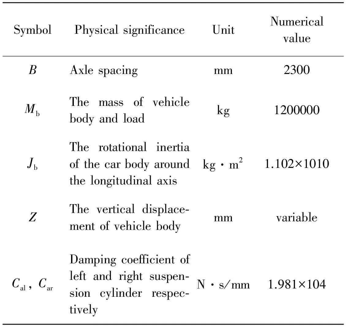
Table 1 The explanation of symbols and parameters

Continued Table 1
An active suspension dynamical model of 1000t BTLV is derived by using d’Alambert which is used for analyzing the kinematic relationship.
Dynamic differential equations of the mass of body and loadMbare

(1)
(2)
Dynamic differential equation of non-suspension mass of left side is

(3)
Dynamic differential equation of non-suspension mass of right-side is

(4)
1.2 The establishment of the state equations

wherex1andx2are the vertical displacement and velocity of vehicle’s body respectively,x3andx4are the displacement and velocity of left side non-suspension mass respectively,x5andx6are the displacement and velocity of right-side non-suspension mass respectively,x7andx8are vehicle side slip angle and angular velocity respectively.
State equation of system can be written as follows:
(5)


Eightstatevariablesselectedfromtheabovestateequations,areusedtodescribetime-domainresponseofactivesuspensionsystem,whichprovidesfundamentalbaseforthefollowingresearches.
2 Mechanicalsimulationofactivesuspension
2.1 The simulation of independent suspension
The single-axis simulation model of 1000t BTLV is built using ADAMS/VIEW. The overturning moment parameters are: STEP(time,0.2,0.0,0.201,-1.0E+007), which means the simulation model is acted by a overturning moment at 0.2s, and velocity of 5km/h for simulating 1000t BTLV that encountered detours or transverse slope. The characteristic curve of vehicle side slip angle and LTR are observed with setting simulation time 5s. The time domain response curve of vehicle side slip angleβis shown in Fig.4, and the time domain response curve of LTR is shown in Fig.5.

Fig.4 Time domain response curve of vehicle side slip angleβ
Closer examination of the time domain response curves of above two evaluation indexes shows it takes only 2.4s to stabilize the system. After that, vehicle side slip angleβis 2.5 radians, LTR is 0.61. It is suggested that the anti-rollover effect of independent suspension system without any external active-controlled can’t meet the actual requirements. Therefore, it is necessary to improve the design of an active suspension anti-rollover system of 1000t BTLV.

Fig.5 The time domain response curve of LTR
2.2 Simulation of an active suspension system
2.2.1 PID control of active suspension
The active suspension model of 1000t BTLV based on PID control is built using Matlab/Simulink, which takes LTR as the control object, reducing LTR as the goal, the deviation of the actual and reference LTR as input and the active control force of suspension as output.
The PID control method can yield the system static characteristic and dynamic characteristic results, when some appropriate argument values like proportion adjustment coefficientKp, integral adjustment coefficientKiand differential adjustment coefficientKdare adjusted. The expected control performance of the system, including the system steady state characteristics and dynamic characteristics is achieved by the PID control. According to the relationship between PID control parameters and the time domain response evaluation index, as shown in Table 2, the three parameters are determined by trial and error.

Table 2 The relationship between PID control parameters and the time domain response evaluation index
2.2.2 Fuzzy PID control of active suspension
The structure of the fuzzy controller includes one dimensional, two dimensional and three dimensional fuzzy controllers. The one dimensional fuzzy controller has unstable performance, and the control rules of three-dimensional fuzzy controller are complex. So, the two-dimension fuzzy controller is adopted to reflect more realistic dynamic characteristics of the output under controlled conditions, which is proved in numerous actual projects.
(1) The constructions of fuzzy-PID controller
Differenceebetween the actual value and predetermined value of load transfer rate, and changeecof load transfer rate are used as input variable of fuzzy-PID controller. The modified value of PID control parameters,ΔKp,ΔKi,ΔKd, is taken as output variable of fuzzy controller.
(2) The fuzzy field
The seven language subsets {NB, NM, NS, ZE, PS, PM, PB} are used to describe input variables and output variables of two controllers, which are defined as
e,ec={NB,NM,NS,ZE,PS,PM,PB}
ΔKp, ΔKi, ΔKd={NB,NM,NS,ZE,PS,PM,PB}
The actual value range of 1000t BTLV’s tire load transfer rate is [-0.65,0.65]. The basic field of load transfer change rate is [-3,3], and the fuzzy field of erroreand error changeecis [-3,3] .The fuzzy field of the final PID control parameters is [-1,1]. Accordingly, all the quantitative factors are obtained. Trigonometric function is selected as subordinating degree function of input variables and output variables of the active suspension system.
(3) The rule of fuzzy control
According to the rule of fuzzy control standards, as shown in Table 3, the proposed fuzzy control rule of 1000t BTLV’s active suspension system is made, as shown in Table 4, based on the performance evaluation index and the experimental results.
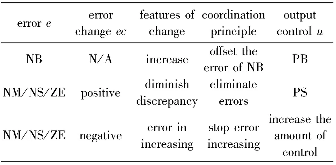
Table 3 Standards of the fuzzy control rule
The fuzzy control rules of 1000t BTLV’s active suspension system can be made, as demonstrated in Table 4
The general expression is:
Ife=ei(NB) andec=eci(NB) thenu=ui(NB)

i=1, 2, 3 … 49 (6)
(4) The fuzzy inference
According to the maximum and minimum methods of Mamdani reasoning, the fuzzy reasoning is applied to study the control set under the rule of fuzzy control. The relationship between the input and output variables of the fuzzy controller can be got by MATLAB/Simulink.
(5) The fuzzy judgment
Fuzzy judgment adopts a gravity method to judge deterministic PID parameters for output control variable.
The single-axis simulation model of 1000t BTLV’s active suspension based on fuzzy control is established, as shown in Fig.6.

Fig.6 The single-axis simulation model of 1000t BTLV’s active suspension based on fuzzy control
2.2.3 Anti-rollover simulation analysis of active suspension under different control strategy
After the combination of the double vehicles, there is no inter-vehicle hydraulic line connection, so the hydraulic system is regulated by each vehicle respectively. The suspension system of each vehicle is adjusted firstly in the process of anti-rollover, and then roll prevention control of double vehicles can be done after ensuring the safety of each vehicle. The anti-rollover control flow chart of parallel double vehicles transporting work is shown in Fig.7.
To prevent anti-rollover accidents, the specific work of double vehicles parallel transporting bridge girder are: when No.1 and No.2 vehicles encounter in rough road conditions (detours, slope), the inclination angle of bridge is detected by angle sensors which are installed on the bridge girder, then a height difference between double vehicles load platform is calculated and fed to the main controller. After that, the main controller sends the rise command to lower vehicle suspension system of load platform, under the principle of keeping the peaks immovability.

Fig.7 The anti-rollover control flow chart of parallel double vehicles transporting bridges
Then all suspension cylinders of the vehicles execute displacement command to raise lower vehicle transporting platform in order to reduce and even disappear side slip angle of bridge girder, so that keeps girder at the horizontal position all the time, which would prevent bridge from rolling over.
The co-simulation of parallel transporting bridge girder of double vehicles based on above method is built in AMESim. The overturning moment is applied to multi-body model in ADAMS, overturning moment is set as: STEP(time, 0.2, 0.0, 0.201, -1.0E+007), in other words, the simulation model is acted by overturning moment at 0.2s, and the velocity of model is set 5km/h for simulating that 1000t BTLV carrying bridge on the road when encountered detours or transverse slope.
The time domain response curves of vehicle side slip angleβand LTR based on different control strategies are analyzed, by comparing with the results without any control strategy.
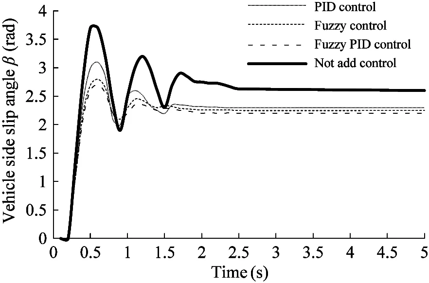
Fig.8 The time domain response curve of vehicle side slip angleβ

RisetimePeaktimeMaximumovershootSteadyvalueNotaddcontrol2.60.730.67%2.6PIDcontrol20.725.81%2.3Fuzzycontrol20.719.64%2.25FuzzyPIDcontrol20.718.52%2.2

Fig.9 The time domain response curve of LTR

RisetimePeaktimeMaximumovershootSteadyvalueNotaddcontrol2.40.535.1%0.61PIDcontrol2.40.539.29%0.51Fuzzycontrol2.40.531.51%0.5FuzzyPIDcontrol2.40.530.77%0.45
Form Fig.8 and Fig.9, it can be seen that evaluation indexes of the vehicle rollover performance and the response rate of active suspension, after adding controller, are improved, and the system tends to be stable finally. In other words, anti-rollover ability of 1000t BTLV is improved effectively. Specific values for response speed via fuzzy PID processing and without fuzzy PID processing are shown in Table 5 and Table 6. It is obvious that anti-rollover effect based on fuzzy PID control strategy is the best, by comparing the evaluation indexes curve of anti-rollover strategy with the PID controller, fuzzy controller and fuzzy PID controller.
2.2.4 Anti-rollover simulation analysis of active suspension on fuzzy PID control
Processing continues in the same way, the overturning moment is applied to multi-body model in ADAMS, overturning moment is set as: STEP(time,0.2,0.0,0.201,-1.0E+007),in other words, the simulation model is acted by overturning moment at 0.2s, and the velocity of model is set 5km/h for simulating that1000t BTLV carrying bridge on the road when encountered detours or transverse slope.
The time response characteristic curves of No.1 and No.2 transporting bridge vehicles are illustrated in Fig.10 and Fig.11, vehicle side slip angle β and bridge roll angle based on fuzzy PID are shown in Fig.10. And the time domain response characteristic curves of LTR based on fuzzy PID are shown in Fig.11.
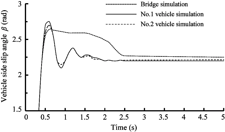
Fig.10 The time domain response curves of vehicle side slip angleβand roll angle of bridge of double vehicles

Fig.11 The time domain response curves of double vehicles of LTR
In the process of double vehicles under anti-rollover control respectively, the vehicle side slip angle and LTR of No.1 and No.2 vehicles decrease gradually, and tend to be stable state, but bridge roll angle does not change greatly. With vehicle side slip angle and LTR of the No.1 and No.2 vehicles tend to be stable, the bridge roll angle begins to decrease, reaches steady state at about 3s, and finally approached the stable value of 2.25 radians.
3 Field tests
To verify active suspension anti-rollover performance of 1000t BTLV, real vehicle tests are conducted. The tests include one vehicle with bridge and double vehicles with bridge in parallel driving on the cross-slope, as shown in Fig.12.

(a)Single vehicle with bridge driving on the cross-slope

(b) Double vehicles with bridge driving in parallel on the cross-slope
The experimental curves of evaluation indexes on the anti-rollover are obtained from the test by setting load of one vehicle is 1000t, load of double vehicles in parallel is 2000t, velocity is 5km/h, road cross slope is 5%. By comparing with the corresponding co-simulation curves, good active suspension anti-rollover performance of 1000t BTLV is verified.
The time domain response curve of evaluation indexes of one vehicle anti-rollover with bridge driving is shown in Fig.13, and the time domain response curve of evaluation indexes of double vehicles anti-rollover with bridge in parallel driving is shown in Fig.14.As can be seen from Fig.10 and Fig.11, there is that the co-simulation and real vehicle tests results are basically identical.

Fig.13 Time domain response curves comparison of one vehicle anti-rollover with bridge driving

Fig.14 The time domain response curves comparison of double vehicles anti-rollover with bridge in parallel driving
In order to ensure that the safety bearing area are large enough, the distance of double vehicles needs to take a larger value, which makes 1000t BTLV to accommodate the road cross slope in poor performance. Based on above issues, slope should be reduced to prevent 1000t BTLV from rollover accident by reconstructing pavement. Besides, rollover accident probability of 1000t BTLV could be reduced by reconstructing pavement, when the distance of double vehicles is limited for the working environment, namely the safe bearing area of the bearing platform is smaller.
4 Conclusion
An independent suspension system without any external active control can’t meet the anti-rollover effect actual requirements from the simulation analysis, by vehicle side slip angle and load transfer rate (LTR) regarded as the evaluation indexes.
The actions of all suspensions and the control force of suspension cylinder are adjusted for reducing vehicle side slip angle and LTR, by taking anti-rollover control strategy of active suspension system cooperated with fuzzy PID control and blending both vehicle side slip angle and LTR. From the co-simulation of the mechanism, electron, hydraulic and real vehicle tests, it is verified that the load barycenter shift of 1000t BTLV by using the control strategy can be effectively controlled when 1000t BTLV encountered the circumstances of cross slope or curve.
1000t BTLV rollover accident would be prevented effectively by maintaining the passive measures and adding the anti-rollover control strategy of active suspension cooperated with the fuzzy PID control strategy as assistant tools. It is significant for expending the application range in the field of engineering.
[ 1] Wang X Y, Zhao J Y, Xu L J.Fuzzy decoupling control strategy for synchronous bridge lifting.ChineseJournalofConstructionMachinery, 2015,13(4): 347-352+371
[ 2] Kadir Z A, Hudha K, Jamaluddin H, et al. Active roll control suspension system for improving dynamics performance of passenger vehicle. In: Proceedings of the International Conference on Modelling, Identification & Control, Shanghai, China, 2011. 492-497
[ 3] Sampson D J M, Mckevitt G, Cebon D. The development of an active roll control system for heavy vehicles.AcsMedicinalChemistryLetters, 2000, 3(11): 897-902
[ 4] Miege A J P, Cebon D. Optimal roll control of an articulated vehicle:Theory and model validation.VehicleSystemDynamics, 2005, 43(12): 867-884
[ 5] Zhao D X. Articulated Vehicle Stability and Simulation and Control. Beijing: China Railway Publishing House, 1997. 1-8
[ 6] Yu Q, Ma J. Analysis of improvement on automobile roll stability with active suspension system.ChinaJournalofHighwayandTransport, 2005,18(3):114-117
[ 7] Zhao J Y, Guo R, Wang Z Y. The developing of independent suspension and its electro-hydraulic control system of heavy platform vehicle.JournalofNortheasternUniversity(NaturalScience), 2008,29(S2): 237-240
[ 8] Liu X L, Zhang J W, Chen Z N. An approach of self-tuning control for automotive active suspensions.AutomotiveEngineering,1998,20(3):165-170
[ 9] Yu F, Guo K H. The potential vehicle’s performance improvements on adaptive suspension.ChinaMechanicalEngineering,1998,9(6):67-69+94
[10] Sun J M, Yang Q M, Chen Y Q. Study on LMS adaptive control of vehicle active suspension system.ChinaMechanicalEngineering, 2003,14(24):90-93+7
[11] Sun J M, Wang Z Q, Zhang X Y. LMS adaptive control of vehicle active suspension system.AutomotiveEngineering, 2003,25(4):360-363
[12] Liu Z, Zhu X C, Luo C, et al. Backstepping based optimal control design and simulation of hydraulic active suspensions applied to a half-car model.JournalofNationalUniversityofDefenseTechnology,2006,28(4):115-120
[13] Liu Z, Zhu X C, Luo C, et al. Backstepping-based optimal control design of hydraulic active suspension applied to a full-car model.ControlTheory&Applications, 2008,25(1):1-8
[14] Jin Z L, Zhang H S, Ma C Z, et al. Vehicle rollover warning based on dynamic stability.JournalofMechanicalEngineering, 2012,48(14):128-133
[15] Jin Z L, Zhang J L, Ma C Z, et al. Robust control strategy of passenger car rollover prevention with multi-population genetic optimization.JournalofMechanicalEngineering, 2014,50(24):130-136
[16] Zhang C H, Zhao J Y, Tian X, et al. Applications of semi-active hydro-pneumatic suspension system based on fuzzy control in articulated dump truck.ChinaMechanicalEngineering, 2014,25(18):2550-2555
Guo Rui, born in 1980. He is currently an associate professor in mechatronics engineering at Yanshan University, China. He received his Ph.D degree from the Department of Mechanical Engineering of Yanshan University, Qinhuangdao, China, in 2010.His research interests include innovative design and reliability of complex electromechanical products.
10.3772/j.issn.1006-6748.2017.02.013
①Supported by the National Natural Science Foundation of China (No. 51405424, 51675461, 11673040) and Hebei Province Natural Science Foundation of China (No. E2012203071).
②To whom correspondence should be addressed. E-mail: guorui@ysu.edu.cn
on July 27, 2016
 High Technology Letters2017年2期
- High Technology Letters的其它文章
- Negation scope detection with a conditional random field model①
- A transition method based on Bezier curve for trajectory planning in cartesian space①
- Closed-form interference alignment with heterogeneous degrees of freedom①
- A case study of 3D RTM-TTI algorithm on multicore and many-core platforms①
- Semantic image annotation based on GMM and random walk model①
- Mining potential social relationship with active learning in LBSN①
