User-guided line abstraction using coherence and structure analysis
Hui-Chi TsaiYa-Hsuan LeeRuen-Rone Leeand Hung-Kuo Chu
User-guided line abstraction using coherence and structure analysis
Hui-Chi Tsai1,2,Ya-Hsuan Lee1,Ruen-Rone Lee2and Hung-Kuo Chu1
Line drawing is a style ofimage abstraction where the perceptual content of the image is conveyed using distinct straight or curved lines.However, extracting semantically salient lines is not trivial and mastered only by skilled artists.While many parametric filters have successfully extracted accurate and coherent lines,their results are sensitive to parameter choice and easily lead to either an excessive or insufficient number of lines.In this work,we present an interactive system to generate concise line abstractions ofarbitrary images via a few user specified strokes.Specifically,the user simply has to provide a few intuitive strokes on the input images,including tracing roughly along edges and scribbling on the region of interest,through a sketching interface.The system then automatically extracts lines that are long, coherent and share similar textural structures to form a corresponding highly detailed line drawing.We have tested our system with a wide variety of images.Our experimentalresults show that our system outperforms state-of-the-art techniques in terms of quality and efficiency.
line abstraction;interactive drawing; coherence strokes;structure strokes; stroke matching
1 Introduction
Line drawing is a style ofimage abstraction in which a distinct and concise set of line strokes is used to depict the shapes of objects in a scene.Such concise image abstraction plays a fundamental element in many artistic stylizations where the artists delicately draw long coherent lines along semantically salient features in an image to give a first impression of their artworks.Beyond artistic drawings,good line abstraction also provides valuable priors for advanced image processing and scene understanding tasks that demand precise edge detection.
However,generating semantically meaningful line abstractions is not a trivial task;it is currently approached in two very different ways.One way, mostly appreciated by artists,is to utilize various commercial painting tools(e.g.,Paint,Photoshop) to precisely trace the salient features by hand. Although this offers the artists full control over the finalresults,the process is tedious,time-consuming, and probably error-prone due to fatigue.In the other approach,a huge body of work is dedicated to automatic line abstraction in various contexts, ranging from gradient-based edge detection[1]to artistic abstraction[2].While such automation largely eliminates the manual eff ort required and achieves pixel level accuracy,the results are highly sensitive to parameter settings,leading to either excessive or insufficient detail.Overall,we still lack an efficient and effective technique to extract concise yet semantically meaningful line abstractions from images.
In this work,we present a novel line abstraction algorithm to extract prominent line strokes from a highly detailed line drawing under the supervision of a few user specified strokes.The key insight isto leverage both the cognitive ability of humans and the computational power of machines to accomplish the line abstraction task.To minimize the fatigue,the user simply has to scribble roughly along the long image features(e.g.,contours of objects)or on a region with similar texture patterns via a sketching interface.The system then automatically performs the accuracy-demanding and computationally expensive tasks of extracting a concise yet semantically meaningful line abstraction from a highly detailed one.Specifically,the system first classifies the user strokes intocoherenceandstructurestrokes,based on which the long coherent lines and line segments that share similar texture patterns in the input image are extracted, respectively.Figure 1 shows a typical example generated by our system using only a few handdrawn strokes.We have tested our system on a variety ofimages across different users.Experimental results show that our system can generate superior or comparable line abstractions given the same input user strokes in comparison to previous state-of-theart methods,and provides a significant performance boost over hand drawing when a target complexity of abstraction is requested.
In summary,our main contributions include:
•An easy-to-use sketching system that facilitates the creation of concise,semantic line abstractions using very simple and intuitive user strokes.
•A novel line matching algorithm for extracting long coherent lines and line segments with similar image domain structure usingcoherenceandstructurestrokes respectively,that are automatically derived from the user strokes.
2 Related work
Parametric image filtering.Parametric image filters such as the Canny edge detector[1]and the difference-of-Gaussians filter[2–4]are widely used in image abstraction for generating line drawing images.However,the quality of output may vary significantly when adjusting the associated control parameters,leading to either excessive or insufficient details.Another well-known contour detector,global probability of boundary(gPb)[5,6]combines both local and global image features,and requires a single threshold parameter to control the number of detected edges.Nevertheless,it remains difficult to find a universally applicable setting that produces satisfactory results for different input images. Rather than struggling to optimize parameters,our work aims to utilize these well-defined filters to generate over-detailed line drawing images,from which a concise set ofsemantic lines is then extracted via the user specified strokes.
Sketch-based refinement.Limpaecher et al.[7]introduced a method to correct user input strokes by a consensus model collected from a crowdsourced drawing database.Su et al.[8] presented theEZ-Sketchingsystem that snaps user strokes to nearby edges using a novel three-level optimization.These systems also resemble those that snap the cursor or strokes to some specific image features such as image snapping[9]and lazy snapping[10].Other interactive sketching systems such asShadowDraw[11],drawing assistant[12], and iCanDraw[13]targeted providing a tutor-like drawing system for novice users.In contrast to previous works that intend to correct or guide user strokes,our system aim to use user stokes as guidance to effectively extract prominent lines that match the user’s intentions from a detailed line drawing image.

Fig.1 Given an input image(a)along with a few scribbles by the user(b),our system automatically extracts a concise line abstraction withcoherenceandstructurelines depicting the edges of the petals and the shapes of the pistils(c,d).Note that our system can adaptively produce highly detailed line drawings using diff erent image filters(see insets).
Stylized line drawing.RealBrush[14]used scanned images of real natural media to synthesize the texture appearance of user strokes.A portrait sketching system by Berger et al.[15]is capableof synthesizing a sketch portrait from a photograph that mimics a particular artistic style.Both systems are data-driven and achieve impressive results by analyzing the relationship between input strokes and the collected line abstraction database.Our system can contribute to this line of work by serving as an efficient tool for generating line abstractions with various styles.
Our work is closely related to the work by Yang et al.[16]who also tried to extract semantic gradient edges based on input user strokes.Their system first clusters edge points into edgelets and constructs a graph that encodes the spatialrelations between the edges near the user strokes.An energy minimization framework is then used to select the semantic edges that conform to the shapes ofthe user strokes. However,their line matching algorithm may produce artifacts such as disconnected edges even ifthe input strokes are coherent.Moreover,lacking support for structure analysis in the texture domain,their system requires users to provide strokes at diff erent scales in order to extract the corresponding gradient edges.
3 Overview
An overview of our system is provided in Fig.2.Given an input image,our system starts by the user providing rough scribbles on the regions of interest(see Fig.2(b))to guide line abstraction. In addition to the user strokes,our system also takes as input a detailed line drawing of the input image(see Fig.2(c)),which provides a reference dataset of line segments used in the subsequent matching algorithm.Such a detailed line drawing can be obtained by using any suitable well-known image filter,such as the Canny edge detector[1],fDoG[2], gPb[5,6],etc.Then our system runs in two stages.
Stroke classification.The user has to provide only two kinds of simple and intuitive strokes:(i) roughly tracing long image features(e.g.,outlines, edges),and(ii)scribbling on the regions using zigzag or circular strokes.We refer to the former type of strokes ascoherencestrokes.These are simple lines that are nearly straight,and are usually used to depict the main shape of objects(see Fig.2(d)).The other stroke type,structurestrokes,are mainly used to indicate regions of interest that contain repeated texture patterns,which are otherwise tedious to trace by hand(see Fig.2(e)).Since these two types of strokes represent different intentions of the user,our system employs a gesture recognition technique[17] to classify the user strokes.
Line matching.We formulate line abstraction as a line matching problem,the aim being to extract lines from the reference dataset that match the user specified coherence and structure strokes(if any).Specifically,for each coherence stroke,the system computes the best matching coherence lines (see Fig.2(f))using metrics favoring candidate lines that are smooth and in agreement with the user stroke in terms oforientation and overalllength(seeSection 4.1).For each structure stroke,the system first analyzes a representative feature descriptor based on texture patches of the input image by sampling along the stroke using a localwindow.Then the corresponding structure lines are those lines of the reference dataset that are close to the user stroke in feature space(see Fig.2(g)and Section 4.3).The finalresult is obtained by combining these two types of extracted lines.
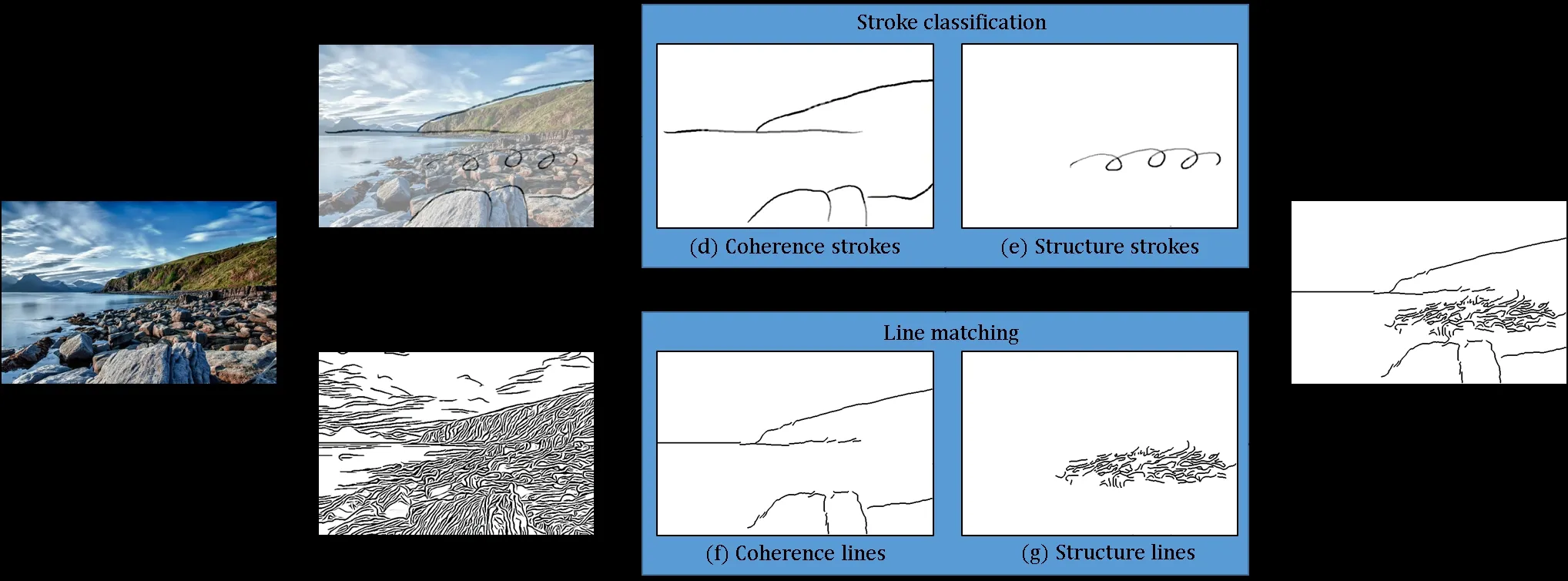
Fig.2 Overview.Given an input image(a),the system lets the user provide a few simple,intuitive strokes(b)and generates a reference dataset of line segments from a detailed line drawing image(c).Next,the system classifies the user strokes intocoherencestrokes(d)andstructurestrokes(e).A novel line matching algorithm is then employed to match the line segments of(c)to the input coherence and structure strokes.The best matching coherence lines(f)and structure lines(g)are combined to form the final line abstraction(h).
4 Algorithm
Preprocessing.The system starts by preprocessing the input detailed line drawing image to obtain a dataset of atomic line segments for the subsequent matching algorithm.This is done by splitting long continuous lines into small line segments according to both length and curvature constraints.Assuming a line comprises a set oftconsecutive pixels{p1,···,pt},we measure the curvature ofpiusing the angleθbetween two vectors,andIfθis less than 135°or the length ofthe line exceeds a threshold of 20 pixels,we subdivide the line into two line segments.The splitting process is iterated until no more line segments violate the length and curvature requirements.
We define a region of interest(ROI)for each user stroke to speed up the process,by constraining candidate matching line segments to those intersecting the ROI.The ROI is defined as the region swept by a disk aligned with and moving along the user stroke.We use an empirical setting of 15 pixels as the default disk radius to generate all results presented in the paper.
4.1 Coherence line matching
Coherence strokescorrespond to the user’s intention to trace along the contours of an object to depict its overall shape.Therefore,the goal in this step is to extract line segments to form a long coherent line that matches each user stroke in terms oflength and orientation.The details of algorithm are as below.
Graph construction.For each input coherence stroke,the system first constructs a directed graphG=(V,E),with vertex setV={v1,···,vm}containing allcandidate line segments covered by the stroke’s ROI;we add a directed edge for every pair of distinct vertices.The edges can be further divided into two types according to context.The edge is labeled as arealedge if its two vertices(i.e.,line segments)are originally connected in the source line drawing image,otherwise it is labeled as avirtualedge.We defer the discussion of how to determine the direction of each edge untillater.An example of such a digraph can be seen in Fig.3.
Vertex-wise energy term.Assume the coherence stroke is also split into a set of stroke segments,denotedS={s1,···,sn}.For each vertexvi,we search among the setSand assignvito the best matching stroke segment according to analignmentfunction,formulated as

The distance cost,Cdistance,calculates the average distance betweenviandsj,and is defined as

The orientation cost,Cangle,measures how wellviis aligned withsj,and is defined as

whereθrepresents the acute angle betweenviandsj,andαis a weight which is empirically set to 2 in our experiments.
Edge-wise energy term.Since our purpose is to extract a path in the graph that is coherent with the input stroke,the edge direction should naturally follow the drawing direction ofthe input stroke.The edge direction is determined by computing the angle between a pair of line segments(vi,vj)and their best matching stroke segments(si,sj).As shown in Fig.4(b),we calculate the angle,θ,between the two vectorsandwheremsandmvare the midpoints ofsiandvi,respectively.
The edge direction is set fromvitovjifθis less than 90°,otherwise it is set to the opposite direction.
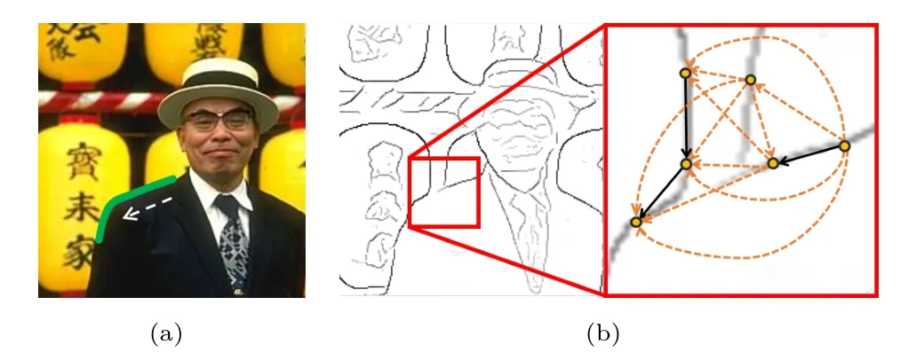
Fig.3 Graph construction.(a)A coherence stroke(green)drawn by the user;direction shown by white arrow.(b)(Right)corresponding digraph based on the detailed line drawing(left).Each vertex represents a line segment.Realedges:black arrows.Virtualedges: orange arrows.Directions of edges are consistent with the direction of the input stroke.
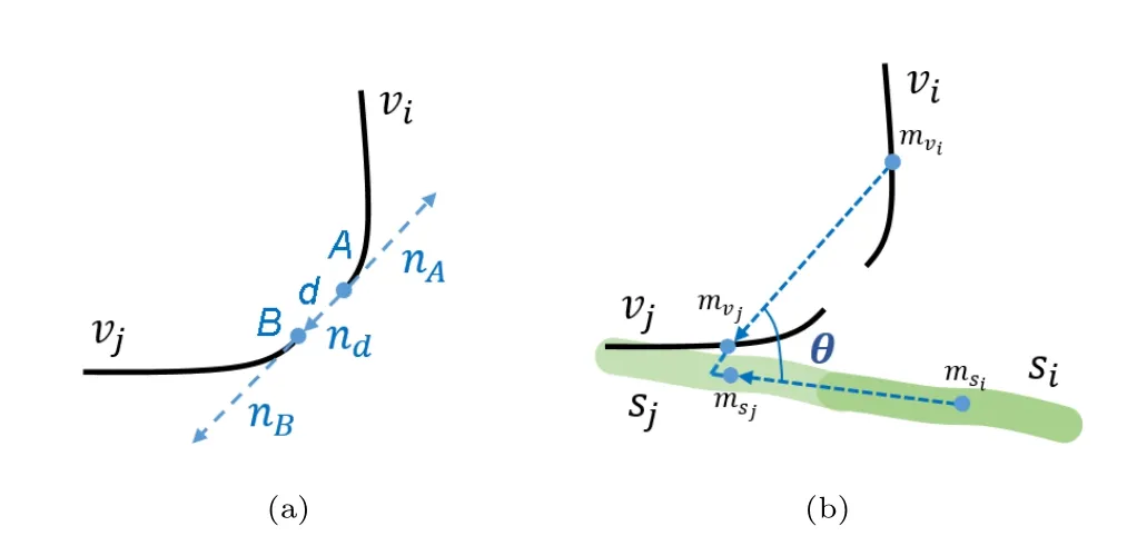
Fig.4 Continuity measure for a pair of line segmentsviandvj.(a) Two line segments with strong continuity in terms ofCline.(b)Two line segments with weak continuity in terms ofCuser.Edge direction is decided by the angle between line segments and the matching stroke segments.
The associated edge weightW(vi,vj)is determined based on the continuity between each pair of line segments(vi,vj),defined by

The continuity cost,Cline,takes into account the geometric feature of the two line segments,and is defined as

wherenAandnBare the unit tangent vectors at pointsAandB,which correspond to two points respectively on line segmentsviandvj.dis the distance vector from pointAto pointB,andndis a normalized unit vector alongd.Figure 4(a) illustrates a case with smallCline.For real edges,Clineis set to 1.Note that Eq.(5)is a slight modification of the discontinuity term introduced in the stage of stroke clustering in Ref.[18].
However,in some cases,two geometrically connected line segments may actually come from two semantically different objects.Take Fig.3 for instance:although the line on the left hand side of the window is long continuous,it is actually made up of edges from different objects(i.e.,the shoulder and the lantern).To handle such cases,we introduce another continuity cost,Cuser,using the indication from the coherence stroke to determine whether two line segments have strong or weak continuity.This cost function is defined as

whereθis the angle between two line segments and their matching stroke segments.Whenθis large,it means that the user intends weak continuity between two line segments even though they show strong continuity in terms ofCline.Figure 4 illustrates a case with smallClineand largeCuser.
Optimization.Given the directed graph,we apply the Floyd–Warshallalgorithm[19]to compute all pairs of shortest paths to find the most coherent path for each pair ofvertices.In order to extract the most prominent paths,we define an energy function,E(p),to measure the quality of each pathpas follows:

The alignment energy term,Ealign,simply averages the alignment cost along the pathpand is defined as

whereNpis the number of vertices on pathp.The length energy term,Elength,computes the proportion of matched user stroke segments of each path and favors the length of extracted lines to be as close as possible to the coherence stroke.Elengthis defined as

whereNmatchedis the number of matched stroke segments andNuseris the number ofstroke segments. For the coherence energy term,Ecoherence,we simply average the edge weight along the pathp:

whereNp−1 is the number of edges on pathp.The three energy terms are combined using weighting parameters,a,b,andc.The path with minimal total energy is selected as the most prominent line that matches the input coherence stroke.Note that we use the empirical values ofa=b=c=1 as default values to generate all results shown in the paper.Figure 5 shows some results of coherence stroke matching.
4.2 Temporospatially neighboring strokes
To distinguish coherence strokes that are close to each other,a co-analysis of multiple strokes is performed to match them to different nearby image lines with respect to the underlying image edges,as proposed in Ref.[8].In this paper,we implement a similar function to distinguish temporospatially neighboring coherence strokes.

Fig.5 Coherence line matching results.(a)Input images and user specified coherence strokes.(b)Detailed line drawings using fDoG[2]. (c)Lines extracted by coherence line matching.
The temporal neighboring relationship is determined by the drawing order.We first take the most recent coherence stroke as the temporal neighbor of the new coherence stroke.For its spatial neighbor,we consider itsparallel neighborand itscontiguous neighbor.The parallel neighbor is defined to be the neighboring stroke that is closest in distance and nearly parallelto the current stroke. They arise when the user wants to extract lines that are close to each other but find it difficult to precisely align them when using hand sketching. In order to avoid extracting the same lines when parallelneighbor strokes are given,we use an energy function to balance the results for such neighbor strokes:

whereandare the candidate paths derived from the current strokepcand the neighbor strokepn,respectively.E(p)is the energy function defined in Eq.(7).Econflictis an energy term designed to prevent the same lines from being extracted for parallel neighbor strokes.It is given by

whereNconflictis the number of duplicated line segments.
The contiguous neighbor is defined to be a neighbor stroke that should be connected with the current stroke.They arise when the user wants to draw a long stroke,but,for some reason,uses two separated strokes to express this intent.In order to extract aligned,long,and coherent image lines,we use a similar energy function to that in Eq.(7)to balance the results of contiguous neighbor strokes.


Fig.6 Temporospatially neighboring strokes.(a)User input with parallel neighboring strokes on the left and contiguous neighboring strokes on the right.(b)Extracted lines without applyingEparallelandEcontiguous.(c)Extracted lines usingEparallelandEcontiguous.
4.3 Structure line matching
Matching of structure strokes requires us to collect evidence covered by the structure stroke.A structure cost is then used to evaluate structure similarity to the collected evidence.
Evidence collection.For a structure stroke, we need to extract line segments that have similar properties in the drawing region.The structure strokes do not need to align with the image lines,but are used for region identification.Sufficient evidence is collected as a basis to infer all other image line segments that match similar structures within the search range indicated by the user input stroke. Firstly,intersections of the user input stroke with the line segments from the line image are gathered. Secondly,for each intersection,we obtain two 3×3 patches along the tangent line on both sides of the intersected image line segment at the intersection point.Lastly,the means of these two patches are calculated.All such pairs of means are used as the evidence for testing structure similarity of line segments in the search range.Note that the search range is the same as for coherence strokes,with radius of 15 pixels.Figure 7 shows an example of evidence collection.
Structure cost.After collecting all possible evidence,the image lines that meet the search range are considered to be candidate line segments for extraction,depending on their structure similarity. For a candidate line segmentvihavingNpoints,its color differenceDcolor(vi,R)to the set ofevidenceRis defined as

whereeviis a collection ofpairs ofmeans,calculated by the way as for the evidence,for every point ofvi.The operatorrepresents the CIE94 color distance[20]measured inL∗a∗b∗color space.
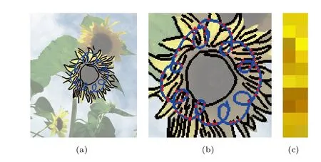
Fig.7 Evidence collection.(a)Blue scribble:input structure stroke,black lines:candidate line segments.(b)Close-up;red dots: intersections of user strokes and candidate line segments.(c)10 pairs of means,out of 67 in total,illustrate examples of evidence.
For each mean pairm,we find the most similar evidence pairrwith the smallest color difference from the evidence setR.The average of the smallest differences for allpoints ofviis regarded as the color difference of the entire candidate line segment.The structure cost functionCstructure(i)is then calculated for each candidate line segmentvi:

whereDcoloris the color difference of a candidate line segment to the collected evidence set,andlkis the image line which line segmentvibelongs to before line splitting.W(lk)is a weighting function depending on the length ofthe specific candidate line segmentvi,and is defined by

wherelminandlmaxare respectively the shortest and longest lengths of candidate lines before being split. This formulation causes matching to favor image lines that are longer in order to provide better line coherence.
To extract appropriate line segments,the candidate line segments are sorted by cost,ones with lower cost being the preferred ones to be extracted.The default proportion of extracted candidate line segments is 70%.The user can also define the proportion of candidate line segments to be extracted.Figure 8 shows some structure line matching results with different proportions of line segments.Here,we enrich the rendering of these line drawings with colors sampled from original images to help clarify the changes between the different cases.
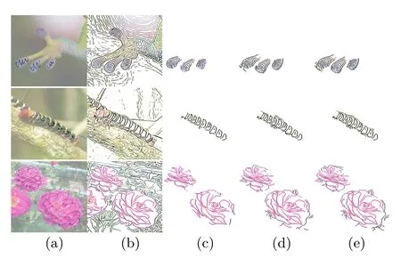
Fig.8 Structure line matching with diff erent proportions of line segments.(a)Input image and structure strokes.(b)Detailed line drawings using fDoG[2].(c)–(e)Line segments with costs less than one,two,or three standard deviations respectively.
5 Results and evaluation
We have tested our system on a wide variety of images across different users and generated 14 line abstractions with only a small number of user strokes.A few examples can be found in Fig.9 and we refer the reader to the Electronic Supplementary Material for a full gallery.
5.1 Evaluation
In this section,we give the results of several experiments to evaluate the performance of our system against naive and state-of-the-art methods. In particular,our system is compared with two stateof-the-art methods by Yang et al.[16]and Su et al.[8] (EZ-Sketching),which share the same goal as our system of generating long coherent lines from user strokes.We also implemented two naive approaches for a baseline comparison,including:(i)extracting lines that are near to the user strokes,within a distance threshold of 15 pixels(NN);and(ii)using all the lines that intersect user strokes(NI).
Performance of coherence line matching. We evaluate the performance of our coherence line matching algorithm against above four alternatives in terms of visual quality and edge detection accuracy with respect to the ground truth.To do so, we used the same benchmark as Yang et al.[16]and took gPb[6]edge maps as input reference line images to our system.For a fair comparison,we imitated 10 results shown in Ref.[16]by carefully tracing their user strokes using our coherence strokes.These coherence strokes were also used as input to EZ-Sketching[8]to generate the outputs for comparison. Figure 10 shows a side-by-side comparison of the results.Our results are visually comparable to those of EZ-Sketching[8],and superior to those of Ref.[16] and both naive approaches in terms of smoothness and conciseness.We further used the precisionP,recallR,andF-measure(the weighted harmonic mean ofPandR)to evaluate edge detection accuracy.Table 1 shows that our algorithm achieves comparable performance to Ref.[16]and clearly outperforms EZ-Sketching[8]in terms ofF-measure. Note that Yang et al.’s method achieves better recall than ours as the ground truths often contain lines that are not expected by the user.For example, in the second row of Fig.10(d),the noisy branches around the man’s contour come from the shape ofthe lanterns in the background,which are also included in the ground truth(see Fig.10(b)).On the other hand,although EZ-Sketching snapped user strokes to nearby edges,it tended to retain the style ofthe user strokes instead of emphasizing the precision of the refined strokes.Therefore,the precision and recall are relatively low.
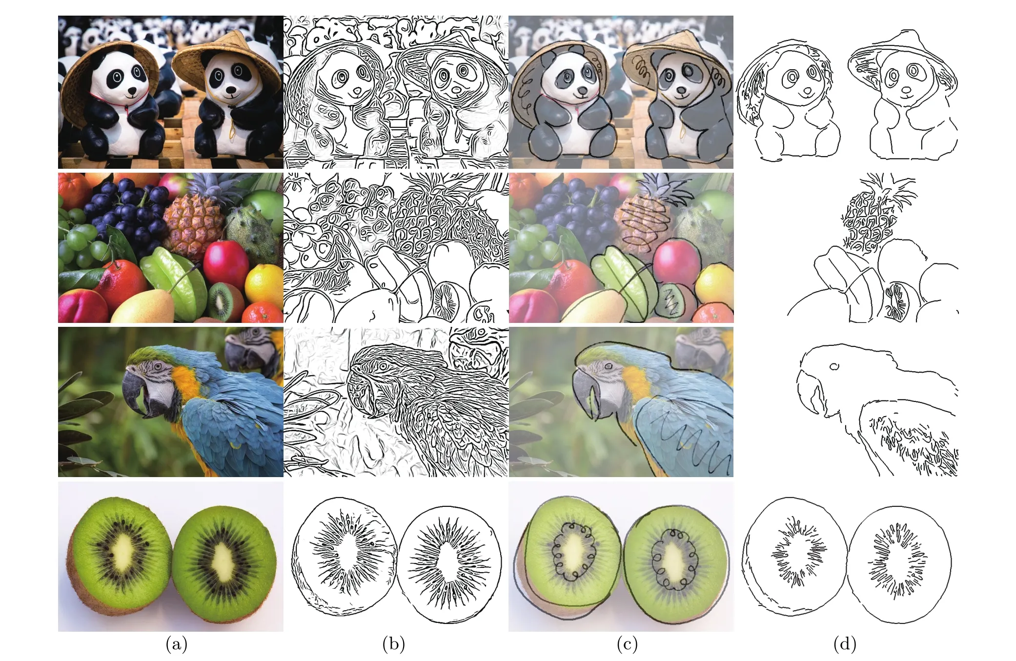
Fig.9 Four results generated using our system.(a)Input image.(b)Detailed line drawings by fDoG[2].(c)User strokes.(d)Final line abstractions.

Fig.10 Comparison with four other methods.(a)Input image and user strokes.(b)Ground truths corresponding to detailed line drawings by gPb[6].(c)–(g)Lines extracted by(c)our system,(d)Yang et al.[16],(e)EZ-Sketching[8],(f)naive near neighbor search(NN),and(g) naive line-stroke intersection test(NI).
Performance of structure line matching. Since neither Yang et al.’s system nor EZ-Sketching are designed to handle scribbles,we evaluated the performance ofthe structure line matching algorithmonly in comparison with naive methods(NN and NI).A side-by-side comparison can be found in Fig.11.Note that we enrich the rendering of line drawings with colors sampled from the original images to better show how our algorithm can effectively capture lines with similar features,while the naive approaches tend to generate results with excessive(NN)or insufficient(NI)details.
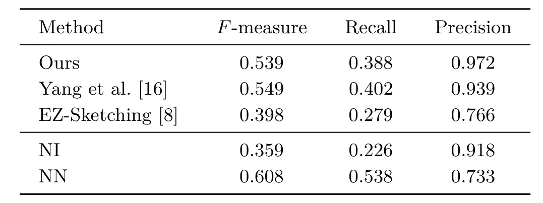
Table 1 Edge detection accuracy
User study.We evaluated the overall quality of line abstractions by conducting a user study. Specifically,we prepared two sets of images,each of which contains 10 example images with predrawn user strokes.One set was used to evaluate coherence line matching while the other was used for structure line matching.For both sets,we generated 3 results for each example using our system and two naive methods(NN and NI).The result generated by EZ-Sketching[8]was also included for the set used to evaluate coherence line matching.During each trial,the subject was shown the originalimage with user strokes and line abstractions by different methods.The subject was then asked to grade each result using a score of 1–5(the higher,the better) according to the degree of completeness,cleanness, and expectation as comparing to the input strokes. The average score over 11 subjects is given in Fig.12.

Fig.11 Comparison with naive methods.(a)Input image and user strokes.(b)Detailed color line drawings by fDoG[2].(c)–(e)Lines extracted by(c)our system with costs less than one standard deviation,(d)naive near neighbor search(NN),and(e)naive line-stroke intersection test(NI).
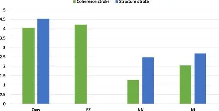
Fig.12 Average scores of diff erent methods in the user study(the higher,the better).
For coherence line matching,there was a statistically significant diff erence between groups as determined by one-way ANOVA(F(3,36)=21.646,p<0.001).An LSD post-hoc test revealed that the score for NN(1.26±0.2,p<0.001)and NI (2.04±0.26,p<0.001)was statistically significantly lower than that for our method(4.05±0.28).There was no statistically significant difference between our method and EZ-Sketching[8](p=0.152).According to the participant feedback,some of them cared more about smoothness and completeness of the coherence lines rather than their precision.Since EZSketching[8]refined the user strokes to snap them to nearby edges,while our method extracted lines from images which were originally composed ofmany incoherent line segments,EZ-Sketching[8]tended to get higher scores for some participants.
For structure line matching,there was a statistically significant difference between groups as determined by one-way ANOVA(F(2,27)= 56.429,p<0.001).An LSD post-hoc test revealed that the score of NN(2.48±0.62,p<0.001)and NI (2.68±0.53,p<0.001)was statistically significantly lower than that for our method(4.53±0.14).There was no statistically significant difference between NN and NI(p=0.355).
System usability.We conducted a small user study with 3 subjects to test the usability of our system against EZ-Sketching[8].During each trial, the subject was asked to generate a line drawing with a comparable level of details to a given reference image using our system and EZ-Sketching[8],and we recorded how long the subjects took to finish the line drawings.The timing statistics can be found in Table 2,and examples are shown in Fig.13.The results indicate that users take more time when using EZ-Sketching[8]to generate a line drawing with a target level of detail.
Speed.Once the user draws a stroke,our systemcan extract the corresponding line segments at an interactive rate.For all the images we tested,our system took on average less than one second to perform coherence line matching or structure line matching.The timing complexity of both line matching algorithms is proportionalto the number of candidate line segments involved in the computation.

Table 2 Time taken to generate line drawings
5.2 Limitations
The quality ofthe extracted lines is currently limited by the input detailed line drawings.First,our system can not extract lines that are not present in the dataset.For instance,the duckling shown in Fig.14(a)presents a jagged outline,as a result of which most image filtering algorithms failto generate long coherent lines(see Fig.14(b)).In such cases, our system can not extract long coherent lines using coherence strokes(see Fig.14(c)).On the other hand,the quality of the extracted structure lines depends on the degree of color diversity in the input image.Since structure line matching depends on color differences ofline segments,the system may fail to extract meaningful structure lines if the reference image lacks color diversity with the stroke’s ROI(see Figs.14(d)–14(f)).
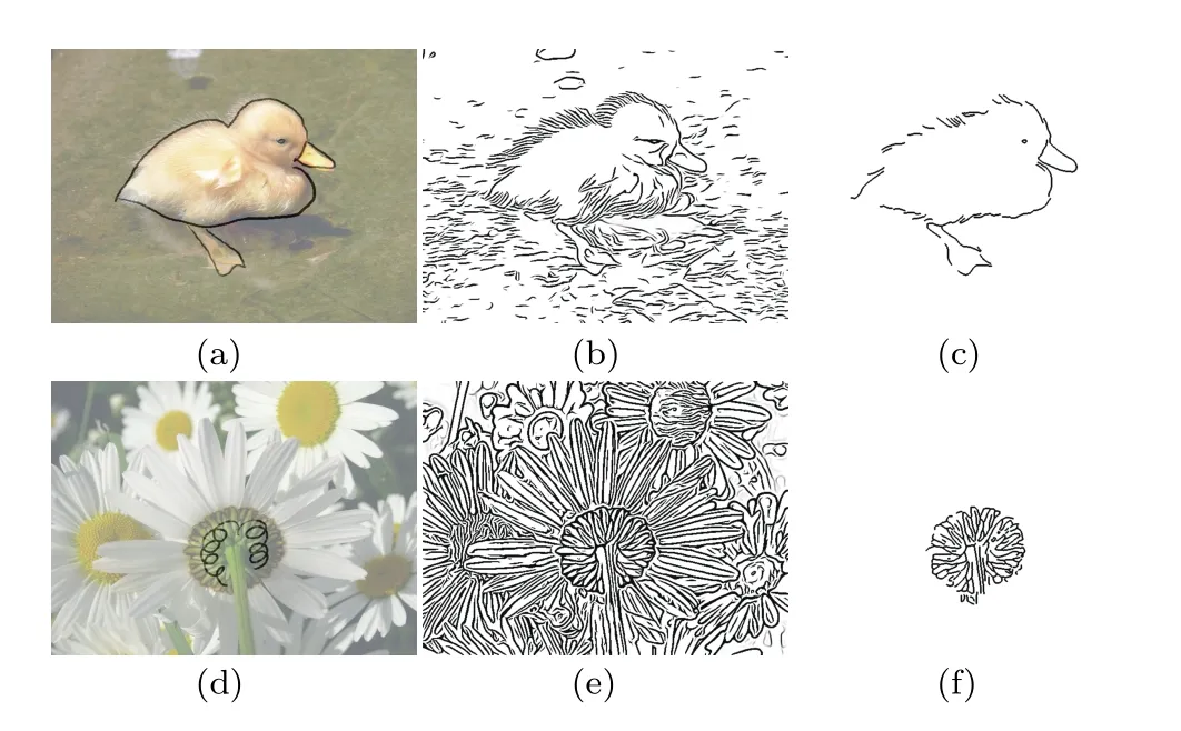
Fig.14 Limitations.(a,d)Input images with coherence strokes and structure strokes respectively.(b,e)Detailed line drawings of(a,d) respectively.(c,f)Line abstractions produced by our system.Note that(c)fails to extract coherence lines due to the noisy line segments along the duck’s boundary in(b).Due to the small color difference between sepals and fl ower stem in(d),our system extracts lines from both sepals and stem even though the user is only interested in the sepal region.
6 Conclusions
In this work,we have presented a novel interactive system for generating a concise,semantic line abstraction guided by a few user strokes.The user strokes are classified into coherence strokes and structure strokes to facilitate extracting effective line drawings from arbitrary images.For a coherence stroke,we build a graph and apply an energy function to extract lines that are coherent and aligned with user strokes.For a structure stroke,we calculate the color difference between the candidate lines and the evidence,and allow lines with similar structures to be extracted.Our system is efficient and can respond in realtime.Its effectivity has been verified by comparing it with other line extraction approaches.The results show that our approach is superior to other systems in terms of quality and efficiency.
Acknowledgements
We are gratefulto the anonymous reviewers for their comments and suggestions.The work was supported in part by the“Ministry of Science and Technology of Taiwan”(Nos.103-2221-E-007-065-MY3 and 105-2221-E-007-104-MY2).
Electronic Supplementary Material Supplementary material is available in the online version of this article at http://dx.doi.org/10.1007/s41095-016-0076-y.
[1]Canny,J.A computationalapproach to edge detection.IEEE Transactions on Pattern Analysis and Machine IntelligenceVol.PAMI-8,No.6,679–698,1986.
[2]Kyprianidis,J.E.;D¨ollner,J.Image abstraction by structure adaptive filtering.In:Proceedings of the EG UK Theory and Practice of Computer Graphics,51–58,2008.
[3]Winnem¨oeller,H.;Olsen,S.C.;Gooch,B.Real-time video abstraction.ACM Transactions on GraphicsVol. 25,No.3,1221–1226,2006.
[4]Winnem¨oller,H.;Kyprianidis,J.E.;Olsen, S.C.XDoG:An extended diff erence-of-Gaussians compendium including advanced image stylization.Computers&GraphicsVol.36,No.6,740–753,2012.
[5]Arbelaez,P.;Maire,M.;Fowlkes,C.;Malik, J.Contour detection and hierarchical image segmentation.IEEE Transactions on Pattern Analysis and Machine IntelligenceVol.33,No.5, 898–916,2011.
[6]Maire,M.;Arbelaez,P.;Fowlkes,C.;Malik,J.Using contours to detect and localize junctions in natural images.In:Proceedings of the IEEE Conference on Computer Vision and Pattern Recognition,1–8,2008.
[7]Limpaecher,A.;Feltman,N.;Treuille,A.;Cohen,M. Real-time drawing assistance through crowdsourcing.ACM Transactions on GraphicsVol.32,No.4,Article No.54,2013.
[8]Su,Q.;Li,W.H.A.;Wang,J.;Fu,H.EZ-sketching:Three-level optimization for error-tolerant image tracing.ACM Transactions on GraphicsVol.33, No.4,Article No.54,2014.
[9]Gleicher,M.Image snapping.In:Proceedings of the 22nd Annual Conference on Computer Graphics and Interactive Techniques,183–190,1995.
[10]Li,Y.;Sun,J.;Tang,C.-K.;Shum,H.-Y.Lazy snapping.ACM Transactions on GraphicsVol.23,No. 3,303–308,2004.
[11]Lee,Y.J.;Zitnick,C.L.;Cohen,M.F.ShadowDraw: Real-time user guidance for freehand drawing.ACM Transactions on GraphicsVol.30,No.4,Article No. 27,2011.
[12]Iarussi,E.;Bousseau,A.;Tsandilas,T.The drawing assistant:Automated drawing guidance and feedback from photographs.In:Proceedings of the ACM Symposium on User Interface Software and Technology,2013.
[13]Dixon,D.;Prasad,M.;Hammond,T.iCanDraw: Using sketch recognition and corrective feedback to assist a user in drawing human faces.In:Proceedings of the SIGCHI Conference on Human Factors in Computing Systems,897–906,2010.
[14]Lu,J.;Barnes,C.;DiVerdi,S.;Finkelstein,A. RealBrush:Painting with examples of physicalmedia.ACM Transactions on GraphicsVol.32,No.4,ArticleNo.117,2013.
[15]Berger,I.;Shamir,A.;Mahler,M.;Carter,E.; Hodgins,J.Style and abstraction in portrait sketching.ACM Transactions on GraphicsVol.32,No.4,Article No.55,2013.
[16]Yang,S.;Wang,J.;Shapiro,L.Supervised semantic gradient extraction using linear-time optimization.In: Proceedings of the IEEE Conference on Computer Vision and Pattern Recognition,2826–2833,2013.
[17]Wobbrock,J.O.;Wilson,A.D.;Li,Y.Gestures without libraries,toolkits or training:A$1 recognizer for user interface prototypes.In:Proceedings of the 20th Annual ACM Symposium on User Interface Software and Technology,159–168,2007.
[18]Orbay,G.;Kara,L.B.Beautification of design sketches using trainable stroke clustering and curve fitting.IEEE Transactions on Visualization and Computer GraphicsVol.17,No.5,694–708,2011.
[19]Floyd,R.W.Algorithm 97:Shortest path.Communications of the ACMVol.5,No.6,345,1962.
[20]McDonald,R.;Smith,K.J.CIE94—A new colourdiff erence formula.Journal of the Society of Dyers and ColouristsVol.111,No.12,376–379,1995.


Ya-Hsuan Lee received her B.S. degree in computer science from“National Tsing Hua University”, Taiwan,China,in 2016.She is currently working at MediaTek as an engineer.Her research interests include computer graphics and computer vision.

Ruen-Rone Lee received his Ph.D. degree in computer science from“National Tsing Hua University”, Taiwan,China,in 1994.From 1994 to 2010,he worked in several IC design companies for graphics hardware and software development.Later,from 2010 to 2015,he was an associate researcher with the Department of Computer Science,“National Tsing Hua University”.He is currently a deputy director in the Information and Communications Research Laboratories,Industrial Technology Research Institute, Taiwan,China.His research interests include computer graphics,non-photorealistic rendering,and graphics hardware architecture design.He is a member of the IEEE Computer Society and the ACM SIGGRAPH.

Hung-Kuo Chu received his Ph.D. degree from the Department of Computer Science and Information Engineering,“National Cheng Kung University”,Taiwan,China,in 2010. He is currently an associate professor at the Department of Computer Science,“National Tsing Hua University”.His research interests focus on shape understanding,smart manipulation,perception-based rendering,recreational graphics,and human computer interaction.
Open Access The articles published in this journal are distributed under the terms of the Creative Commons Attribution 4.0 International License(http:// creativecommons.org/licenses/by/4.0/),which permits unrestricted use,distribution,and reproduction in any medium,provided you give appropriate credit to the original author(s)and the source,provide a link to the Creative Commons license,and indicate if changes were made.
Other papers from this open access journalare available free of charge from http://www.springer.com/journal/41095. To submit a manuscript,please go to https://www. editorialmanager.com/cvmj.
sai
her bachelor and master degrees in computer science from“National Tsing Hua University”,Taiwan,China.She is currently a software engineer in the Information and Communications Research Laboratories,Industrial Technology Research Institute,Taiwan, China.Her research interests include computer graphics and computer vision.
1 Department of Computer Science,“National Tsing Hua University”,No.101,Section 2,Kuang-Fu Road, Hsinchu,Taiwan 30013,China.E-mail:H.-C.Tsai, beck394@itri.org.tw;Y.-H.Lee,louiselee602@gmail.com; H.-K.Chu,hkchu@cs.nthu.edu.tw
2 Information and Communications Research Laboratories,Industrial Technology Research Institute,No.195,Section 4,Chung Hsing Road, Chutung,Hsinchu,Taiwan 31040,China.E-mail: rrlee@itri.org.tw
Manuscript received:2016-09-09;accepted:2016-12-21
 Computational Visual Media2017年2期
- Computational Visual Media的其它文章
- View suggestion for interactive segmentation of indoor scenes
- Feature-based RGB-D camera pose optimization for real-time 3D reconstruction
- EasySVM:A visual analysis approach for open-box support vector machines
- Fast and accurate surface normal integration on non-rectangular domains
- Feature-aligned segmentation using correlation clustering
- Robust camera pose estimation by viewpoint classification using deep learning
