
Simulation and optimization of an industrial gas condensate stabilization unit to modify LPGand NGL production with minimizing CO2 emission to the environment
2017-05-28 07:29:06BahmaniShariatiNematiRouzbahani
M.Bahmani,J.Shariati,2,*,A.Nemati Rouzbahani
1 Young Researchers and Elite Club,Darab Branch,Islamic Azad University,Darab,Iran
2 Department of Chemical Engineering,Darab Branch,Islamic Azad University,Darab,Iran
1.Introduction
1.1.Natural gas products
Natural gas(NG)is one of the world's favorite,promising,and cheap fuels with a wide variety of applications.However,its transportation in the gas state encounters various difficulties.Therefore,in order to smooth the difficulties raised by its gaseous nature,the process of converting NG into intermediate liquid streams has been recommended and applied for years[1].Commonly,two main products namely liquefied petroleum gas(LPG)and natural gas liquids(NGLs)are sourced from NG stabilization units of all industrial gas refineries.As a matter of fact,LPG is a super pressurized gas stored in a liquid form in tanks which is known as a valuable type of gas and remarkable demand in the economical world.This colorless and odorless compound is as twice as heavy as air and as half as heavy as water due to its constituents.LPG is inherently a mixture of two flammable nontoxic gases namely,propane(C3H8)and butane(C4H10)that each of them has a variable portion in different seasons.In winter,it is mainly composed of propane;while,the heavier component(i.e.butane)occupies most of its volume during summer.LPG is produced by refining petroleum or “wet”natural gas,and it is almost entirely derived from fuel sources,being manufactured during the refining of petroleum(crude oil),or extracted from petroleum or natural gas streams as they emerge from the ground[2–5].Moreover,NGLs are commonly determined as heavier hydrocarbons of natural gas which tend to be in liquid state at atmosphere condition.They are mainly composed of methane,ethane,propane,butane,pentane,hexane,and heptane.In a typical natural gas refining plant,various components of NGLs are separated one by one from the natural gas stream by applying a series of fractionation columns namely demethanizer,deethanizer,depropanizer,and debutanizer[6].
1.2.Literature review
Chemical process industries face a lot of operational problems in monitoring and controlling the processes.Up to now,the majority of investigations on problems of gas processing plant focused their attention on different kinds of controlling systems,methods of preventing product loss with special attention to the environmental aspects of the issue and energy consumption of the plant.For instant,in 1998,a comprehensive study covering a diversity of controlling systems was done by Ansariet al.[7].Nonlinear and PID control systems were applied to control the percentage ofi-C5in the top product stream of the plant.Analyzing the results clearly represented that by implementing the nonlinear controlling systems,a better performance can be achieved with respect to PID controlling strategies[8].Environmental pollution especially,CO2emission from all natural gas refinery flare stacks is one of the most serious problems that should be considered.In this regard,in 2014,Davoudiet al.tried to perform a great research on the assessment of flare networks in South Pars Gas processing plant.Actually by modeling the data and calculating the maximum flaring load in five gas refineries,it was revealed that different flare sizing loads caused different values of CO2emission which can be attributed in different fire zone arrangements[9].In the same year,Nemati Roozbahaniet al.investigated the simulation,optimization,and sensitivity analysis of a natural gas plant.Their study was focused on significant parameters playing a central role in the dehydration unit and accordingly,the best operating conditions were determined[10].Afterwards,in 2015,Amidpouret al.presented the sensitivity analysis,economic optimization,and con figuration design of mixed refrigerant cycles by NLP techniques.They showed the one-stage cascade of mixed refrigerant refrigeration cycle(MRRC)as the best option to replace pure ethylene cycle in the olefin plant of Tabriz Petrochemical Complex[11].
Moreover,a steady state simulation was performed by Al-Sobhi and Elkamel for LNG(Liquefied Natural Gas),GTL(Gas to Liquid),and methanol to determine mass and energy balances,operating conditions,and equipment specification.They also investigated the other relevant preprocess units of these utilization processes.Finally,they proposed an optimization model for their simulation[12].
To the best of authors' knowledge,simulation,optimization,and economic analysis of different industrial gas processing such as waste gasification,product loss,and greenhouse gas emission through flaring played an important role in their studies[13–16].
In the current study,simulation and modification of an industrial gas condensate stabilization unit for more LPG&NGL production were investigated under significant operational conditions.Some operational problems of the stabilization unit such as gas flaring and products wasting were verified.
Moreover,CO2emission to atmosphere during more LPG production process as well as economic analysis of the process optimization and modification was studied completely.
2.Process Description
The understudied gas refining plant mainly consists of three distinct units including “a pre-separation and dehydration unit”,“a stabilization unit”,and “an emergency stabilization package”.
Natural gas,which is collected from 8 different gas-wells,enters to the pre-separation unit at nearly 7 MPa operating pressure.Firstly,it runs into six parallel two-phase separators.Then,after the separation process,the outlet gas is collected into one main stream and sent to the dehydration unit for further water content removal and treatment.As a result,its dew point can be decreased to less than−20°C which has a vital role in the process design for produced dry gas.Also,this will prevent forming any kind of hydrate while transportingviapipeline in long distances.The cooling process in the hydration unit is performed using propane as the coolant and Diethylene Glycol(DEG)as wet dehydration agent[10].During this process,a mixture of water,heavy hydrocarbons,and DEG known as wet hydrocarbons,(i.e.stream 8)shown in Fig.1,is produced.This stream will be treated further in another three phase separator(S-404)to avoid the waste of precious liquid compounds.The outlet liquids from the six two-phase separators consist of a significant amount of valuable hydrocarbons.Hence they are collected as the natural gas liquids,(i.e.stream 1)shown in Fig.1,and sent to a three-phase separator known as S-205 where the separation of water content and heavy hydrocarbons from the feedstock proceeds(Fig.1).In this step,the heavy hydrocarbons are separated from water and sent to the stabilization unit along with the outlet hydrocarbons stream from S-404 to produce LPG and NGL.The information about the material specifications of main streams and operational parameters in Fig.1 can be seen in Table 1.
Hydrocarbon fractionation was considered as an essential part of all gas processing plants generally performed by applying a series of distillation columns[17,18].Fig.2 illustrates a schematic diagram of the current stabilization unit(Unit 700).As it is shown,an expansion drum(S-701),two sieve tray distillation towers,i.e.a de-ethanizer(T-701)and a de-butanizer(T-702),and their relevant condensers and reboilers along with a two-phase separator(S-702)for controlling the pressure of de-butanizer tower are the key components constructing the main structure of the whole unit.
The S-701 is inherently a three-phase separator(S-701)which is fed by the output of the upstream unit(pre-separation and dehydration units).In this drum,methane is partially separated from the entering feed stream and directed from the top of the vessel to the fuel gas system.Moreover,the heavier hydrocarbons are recovered from the middle section of S-701 to be further treated in the subsequent fractionation columns.

Fig.1.Schematic view of pre-separation and dehydration equipment and condensate feed gathering line.S stands for separator.
From there,the middle phase stream runs into the de-ethanizer where ethane and lighter components are distilled at 1.8 MPa operating pressure by application of heat.The overhead product then flows into the fuel gas system to be applied in the power generation section of the plant.The C+3rich product which leaves the bottom of the column is directed to the 20th tray of the de-butanizer tower with the ultimate goal of producing liquefied petroleum gas(LPG)as its overhead product.The lighter stream leaving the top of the tower is totally condensed by passing through the coils of the air coolers(E-701 A/B)that are incorporated in down stream of the still column.After that,the condensate which continues flowing into the receiver vessel(S-702)plays the role of a reflux drum.LPG then flows out of the bottom of the vessel and continues its path to the storage tanks by applying a pumping system.
If,for any unfavorable reason,a failure happens in the transition of LPG to the storage tanks,the gaseous mixture will by-pass the air coolers and it will be sent directly to the receiver vessel.In the next step,it is released from the vessel to the low pressure flare stack to be burnt out in order to protect the entire system from facing over pressure problem.This failure can be stemmed mainly from an increase in tower pressure or temperature which will be discussed later in the following sections.The bottom outlet liquid from T-702 which is one of the main product of this unit,is stored at natural gas liquid(NGL)storage tanks after it has been cooled down by the downstream air cooler(E-702).
A brief information about the operating conditions and chemical composition of the main streams and the design criteria for some of the main equipment in the stabilization unit are tabulated in Tables 2 and 3,respectively.
As it has been demonstrated in Fig.3,emergency stabilization package consists of a small gaseous furnace(H-1)and some two-phase separators which will be used only,when the severe malfunction happens at the upstream units causing the whole stabilization unit to be shut down.The main purpose of the unit is to prevent sending both the valuable heavy hydrocarbons to the flare by separating the lighterhydrocarbons and the rest to the NGL tanks.After entering the gas liquids into this package,due to heating the gaseous furnace,lighter hydrocarbons are separated from liquid phase and consumed at the fuel gas system or sent to the flare according to the plant conditions.Consequently,heavier hydrocarbons exit this package and next they will be cooled down and stored as the NGL product.This procedure is demonstrated in Fig.3.Additionally,the information of its related streams is provided in Table 4.

Table 1Components flow rate and thermodynamic conditions for main streams in the pre-separation and dehydration unit(specified in Fig.1)
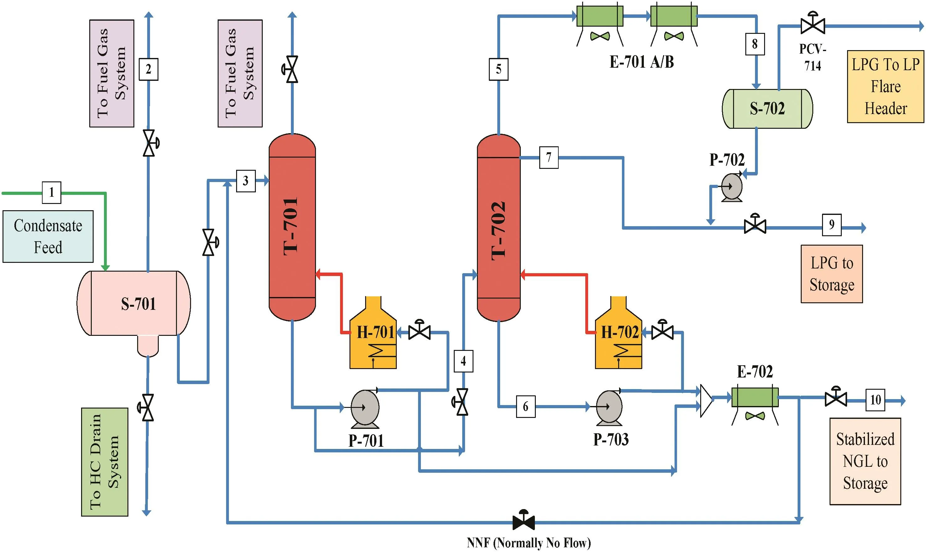
Fig.2.Schematic view of stabilization unit process(Unit 700).S stands for separator,E is for exchanger,P is for pump and H is for heater.
Describing the problem
In the studied natural gas refinery plant,during hot seasons of the year,the ambient temperature may exceed over 50°C at the warmest period of the day.Therefore,in the stabilization unit the efficiency of heat exchangers which use ambient air as the coolant fluid,i.e.E-701 and E-702,will reduce severely.Although,this issue does not incur any major problem for the outlet fluid from E-702,since it heads directly into the NGL storage tank(Fig.2).The main problem occurs when outlet stream temperature from E-701 increases rapidly because of the mentioned issue,resulting in an abnormal temperature pro file at top stages of T-702.It is needless to say that any temperature increment in recycled LPG will increase the vapor pressure of the outlet stream from top stage of T-702.The normal operating pressure of the feed entering T-702 is set on the value of 1.05 MPa.However,in designing of any engineering equipment,the operational condition is under the influence of many factors.Obviously,temperature as an effective parameter has a leading role in the pressure adjustment of many gas associating equipment.Therefore,in the present research,the malfunction of the air-cooler condenser(E-701)and its impact on the temperatureand consequently,the pressure of the tower have been chosen as a case study.It is worth mentioning that the air cooler heat duty cannot be easily changed and there is a limit on the maximum effective duty that can be exchanged with the upper stage vaporous mixture depending on the ambient temperature and the driving power of the air cooler electromotor.For that reason,a secondary air cooler is needed for consuming extra duty and cooling the reflux stream to the proper temperature.Due to the fact that the temperature increment will pose a rise in the volumetric flow rate inside the tower and consequently,a pressure climbs at the upper stages of the column.In order to overcome the problem,an adjustable control valve,i.e.PCV-714 shown in Fig.2,with the set pressure of 1.15 MPa has been embedded just in downstream of the receiver drum.Whenever the vessel pressure reaches 1.15 MPa,the control valve will be opened quickly and as a result,a part of the produced LPG will be sent out to the flare.Moreover,a large volume of greenhouse gases(mainly CO2)will be produced and emitted to the atmosphere during the flaring.

Table 2Components flow rate and thermodynamic conditions for main streams in the stabilization unit(specified in Fig.2)

Table 3Detailed information for designing of major equipment in the stabilization unit
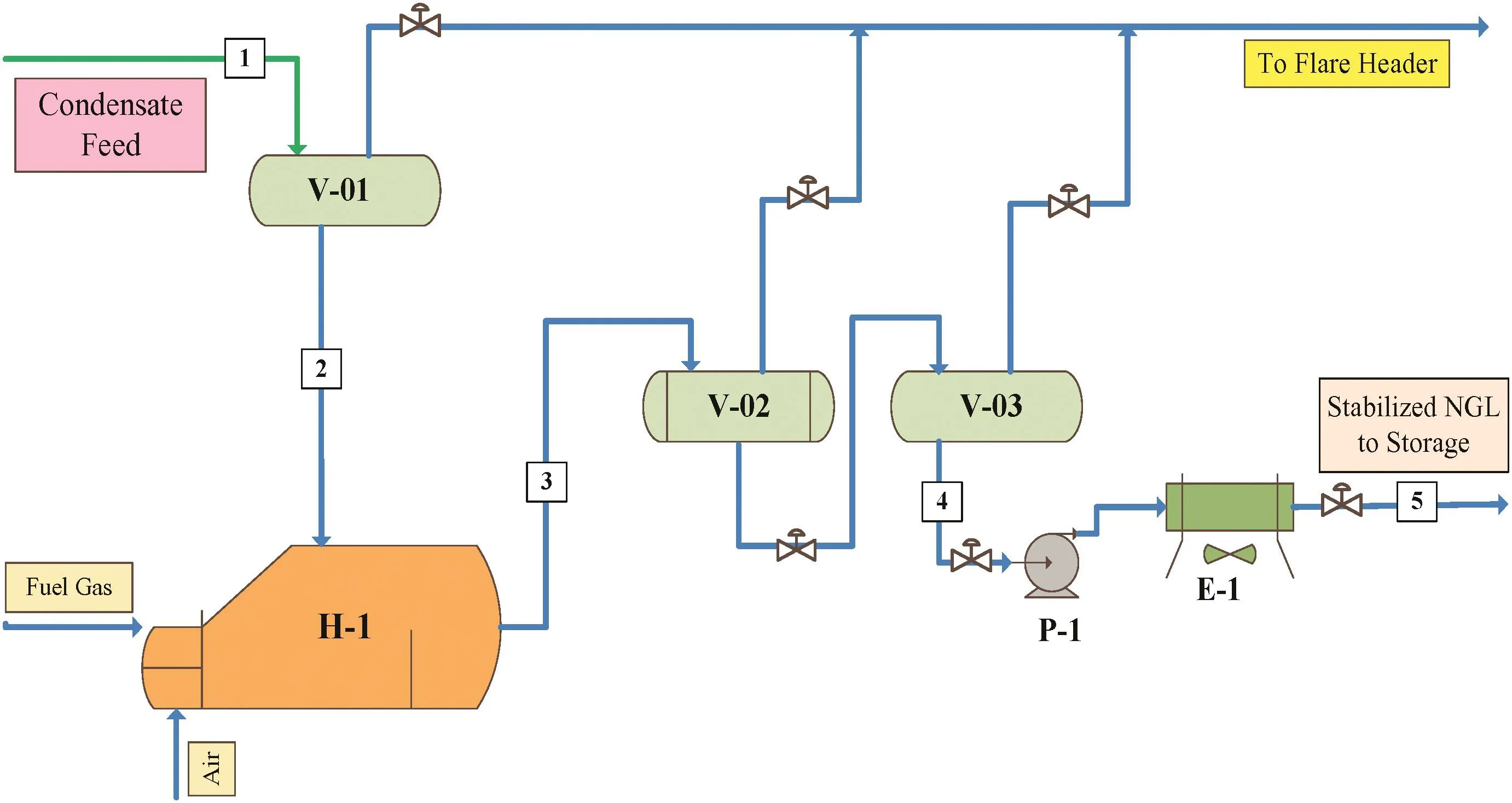
Fig.3.Schematic view of emergency stabilization unit process(Unit 710).V stands for vessel,E is for exchanger,P is for pump and H is for heater.
With considering the maximum allowable working pressure(MAWP)of both the receiver vessel and the de-butanizer tower(Table 3),in a case that their operating pressure exceeds the criterion,the emergency inter-lock control system of the stabilization unit will be activated by preventing the feed stream to this unit,shutting down the reboilers(H-701/702),and consequently shutting down the whole unit.Hence the feed will be bypassed directly to the emergency stabilization unit(Unit 710)for some simple separation and then injected to the NGL storage tanks.Therefore,the LPG production of the plant will be stopped completely at this condition.
The main purpose of the current study is to perform a reliable simulation of the stabilization unit using a steady state flow sheet simulator,Aspen Plus,in order to be able to use a sensitivity analysis tool on the most important parameters in this unit,such as LPG and NGL production rate and produced LPG composition.So the unknown relationship between these parameters and other operational variables like condenser heat duty of the debutanizer tower andetc.can be discovered.It is worth mentioning that,seeking a way to reduce the flaring of LPG and decreasing the emission of CO2to the environment in consequence of high pressure at warm seasons,with keeping the LPG composition at its standard range should be counted as another objective of this article.

Table 4Components flow rate and thermodynamic conditions for main streams in the emergency stabilization unit(specified in Fig.3)
3.Simulation and Sensitivity Analysis
The whole gas condensate stabilization unit was simulated using a steady-state flow sheet simulator.In order to obtain the reliable and accurate results from the simulator,a proper property package must be selected[19].By taking a closer look at the reported operating data of Table 2,due to low molar flow rate of water entering to the stabilization unit,a Peng–Robinson equation of state(EOS)was selected to apply in the current simulation.Also,another factor which motivated us to use this EOS was,its unerring accuracy for systems containing hydrocarbons at moderate operating pressures and temperatures.Nevertheless,in order to make sure that the selected EOS has the best consistency with this case study,a comparison between other proper EOSs is necessary to be performed.Since the case study was hydrocarbon system and by considering the acceptable range of its pressure and temperature,three equations of Peng–Robinson(PR),Lee–Kesler–Plocker(LK–Plock),and Sova–Redlich–Kwong(SRK)were recommended by simulator[20].In order to choose the best equation,the simulation was performed for each EOS separately.A brief result of calculated values by each equation for outlet LPG stream from the debutanizer tower along with the field design data has been tabulated in Table 5.In order to compare the results,an error index namely absolute average relative deviation percentage(AARD)was utilized to investigate the accuracy of each model,individually[21].Eq.(1)shows the relevant relationship for calculating AARD:

whereyopis the actual data,ycalis the calculated result by models,andNis the number of data points.Table 6 indicates the calculated AARD for each model.According to the table,the lowest offset from actual data can be achieved by PR EOS with the value of 5%error;while,LK–Plock calculation has the weakest correspondence with almost 38%offset.It is needless to say that,due to its low generated error,PR property package was selected for the final simulation and sensitivity analysis.

Table 5Calculated values by each equation for outlet LPG stream from the debutanizer tower versus the field design data
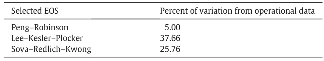
Table 6Calculated AARD for each model
Since the main purpose of the this study is to minimize the LPG flaring from the unit and optimize the performance of its debutanizer tower(T-702),after running the simulation process,a sensitivity analysis should be performed to inspect the effective thermo-dynamic parameters on the debutanizer tower performance.In fact sensitivity analysis is a try and error calculating technique used to determine how sensitive an output of a mathematical model or simulation is to any change in the value of a particular input variable while keeping other independent parameters constant[22].Sensitivity analysis allows modelers to determine what level of uncertainty is acceptable for a parameter to make the simulation reasonably valid.To this end,the main independent and dependent variables must be specified beforehand.Tower pressure,as it has been mentioned before,is the mostcritical parameter in controlling the operation which even a slight change on it can pose severe problems and failures on performance of the whole unit.Tower pressure can be controlled by adjusting the feed pressure through its relevant control valve and can vary from 0.95 to 1.25 MPa(maximum design pressure of the tower).It should be mentioned that because of the design criteria at current situation,the maximum operational pressure of the tower has been set to 1.15 MPa.Other important dependent and independent variables are presented in Table 7.In this study,the sensitivity analysis was performed using the Aspen Plus sensitivity and optimization tools based on the approved simulation of the stabilization unit.

Table 7The important dependent and independent variables for stabilization unit
4.Results and Discussion
4.1.Condenser temperature and duty
As previously mentioned,the debutanizer tower is designed in a way to operate with maximum operating pressure of1.15 MPa.Accordingly,the excess pressure imposed on the column must be modified by flaring a part of LPG that is not an economy-environmental friendly approach.In order to solve this problem,the engineering decisions must be adopted to keep the tower pressure below 1.15 MPa.This will be feasible only,if the temperature pro file of the tower remains sufficiently low.Fig.4(a,b)shows the temperature pro file of debutanizer tower at all stages of the tower and top stages,respectively.
Throughout the entire article,the simulation was performed by considering a constant reboiler thermal loading of 3315 kW.This constant heat duty can be easily applied using a fuel gas burner around the reboiler to produce a constant heat duty by adjusting the flow rate of the required fuel gas and ambient air to be burnt.As it can be observed from Fig.4,the initial trays of the tower have lower temperatures at lower pressures.This can be explained by decreasing the tower pressure which leads to enhance the vapor pressure of lighter components at top trays as well as reduction of their condensation temperature.Consequently,the tower air cooler as a total condenser should cool vapors to lower temperature in order to produce a saturated liquid stream.
In the current study,attempts were made to determine effective parameters during tower pressure alternation and finally,pressure reduction of the tower by considering operational limitations.Due to the limitations exerted on the system,the condenser may not be able to react fast enough to cool the vapor and set the temperature for total condensation of the overhead stream.Thereby,the malfunction of the tube bundled air cooler causes the mentioned equipment to operate as a partial condenser.Thereafter,the outlet stream from the air cooler continues its path to the downstream receiver vessel of S-702.In this vessel the vapor portion of the feed is first separated and after that when the pressure exceeds 1.15 MPa,it will be sent to the flare through the PCV-114 as a waste product.
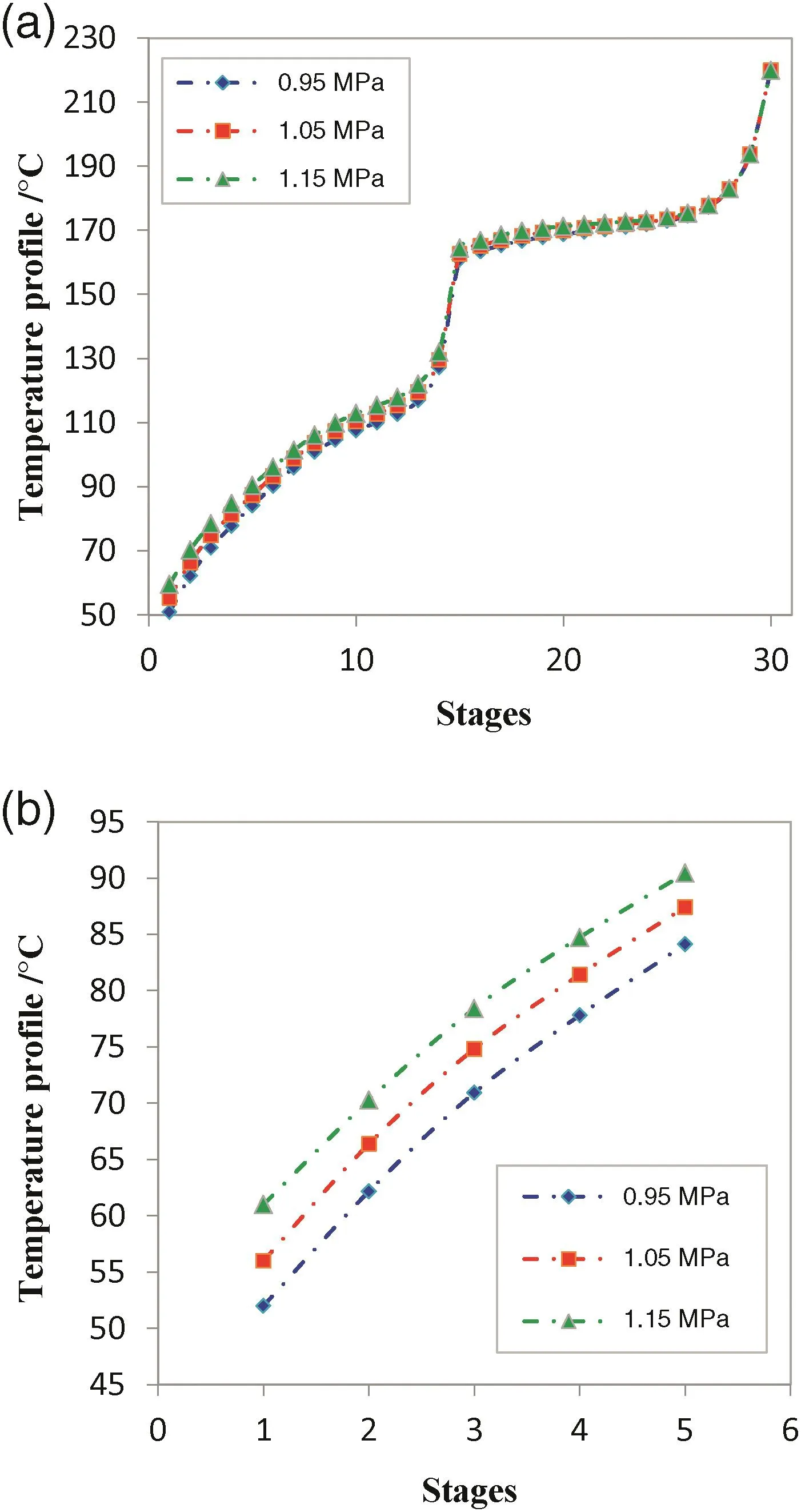
Fig.4.Temperature pro file versus the number of the debutanizer tower stages in different pressures.
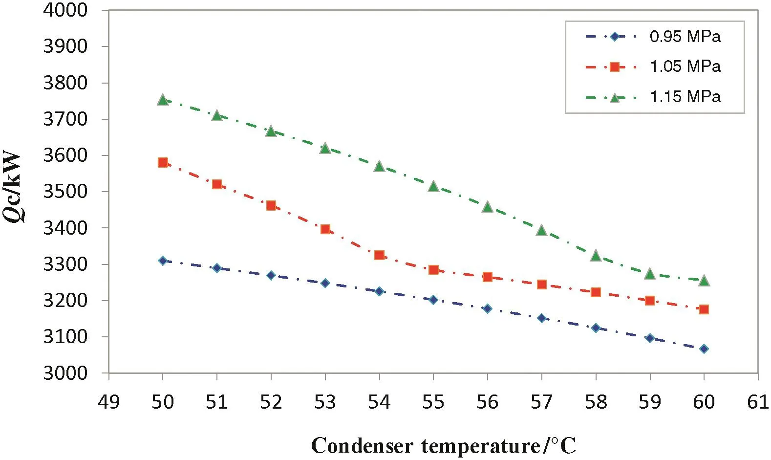
Fig.5.The amounts of condenser energy consumption in different ranges of temperature in hot seasons.
To overcome the problem,the heat exchanger outlet fluid which is a saturated liquid should be cooled by increasing the heat duty of the condenser through adding a secondary air cooler in conjunction with E-701,and then the pressure should be reduced.The degrees of temperature reduction must be proportional to pressure reduction.As it can be estimated from Fig.4(b),1 bar pressure reduction is attained by 4.5°C temperature reduction.Fig.5 indicates the amounts of condenser energy consumption in different ranges of temperature and pressure at hot seasons of the year(considering the average temperature of 45°C for the ambient during day).As it would be expected,at higher pressures,the amount of consumed energy for fluid cooling is more than the lower ones.This phenomenon can be attributed to the reduction of heavier components of the vaporous stream resulting in greater condensation temperature of the mixture.At three mentioned pressures(0.95,1.05,and 1.15 MPa)in Fig.4(a,b),the condensation temperature values for standard LPG stream(stage 1 temperature)according to the composition reported in Table 2 are 52.1,56.0,and 60.5°C,respectively.As it is obvious from Fig.5,at any pressure value,the energy consumption of the condenser varies with steeper slope at lower temperatures;while,the slope becomes gentler at greater condensation temperatures.As one can see from Fig.5,for 0.1 MPa pressure drop in the tower for example 1.15 to 1.05 MPa,it is necessary to cool the reflux stream by about 4.7°C which requires an increase in heat exchanger power from 3275 kW to 3516 kW.By implementing these alternations and attaining the equilibrium conditions,tower pressure can be reduced about 0.1 MPa without flaring any LPG product.Without any doubt,the thermal loading of air cooler should be decreased again(in this stage to 3283 kW)by pressure reduction,in order to prevent the excessive and unnecessary energy consumption.Moreover,according to Table 3,the maximum available heat duty for air cooler condense at operational pressure of 1.05 MPa,is 2950 kW.However,by looking closely at Fig.5 it can be seen that the required heat duty for condensing the whole inlet stream to the condenser,at saturated fluid temperature of 56°C,is 3265 kW.It means that in hot seasons,an extra 315 kW heat duty should be provided in such conditions.Therefore the unit can operate normally.
4.2.LPG and NGL fl ow rate and compositions
Fig.6(a,b)displays the main product flow rate of stabilization unit(unit 700)at different pressures for various condenser outlet temperature.As it can be observed,the amount of produced LPG decreases due to further reduction of reflux temperature.At constant pressure,further thermal loading which leads to convert its fluid to sub-cool state,can change the tower temperature pro file.As a result,heavy and some of light components tend to remain in the liquid phase and leave the tower from its bottom.Clearly,at lower pressures heavier hydrocarbon components will tend to move to the gas phase.Consequently,the production rate for LPG as the main product of the stabilization unit will increase;while,at the same time the flow rate of produced NGL will drop.It should be noticed that decrement of tower pressure and temperature must alter in such a way that mass fraction ofi-C5in produced LPG stream stays lower than 2%.This is an important criterion for designing the plant to produce LPG in standard range and with considering the need of customers.Moreover,the standard range for propane mass fraction in LPG product is determined between 25%and 37% of outlet stream total mass fraction.Fig.7(a,b)indicates variations of propane and isopentaneversuscondenser temperature at three distinct pressures.This figure shows that by reducing pressure while the temperature is held in constant value at top stage of T-702,a higher portion of heavier compound such asi-C5will move to the vapor phase which leads to increase the heavy hydrocarbon composition in LPG final product.Based on the figure,since the air cooler cannot set its inlet stream temperature to fluid dew point,some portions of the produced two phase flow will be sent to flare and waste.Furthermore,this causes the mass fraction ofiso-pentane(i-C5)in the produced LPG to be out of mentioned standard range.For instance,at pressure and temperature about 1.05 MPa and 57°C of reflux stream,thei-C5mass fraction is more than 7%which is against design criteria.However,if the air cooler cools down the reflux stream to 55°C,i-C5mass fraction will drop to 2%which is acceptable.Simultaneously,the C3mass fraction in those temperatures is around 25%and 37%respectively which both of them are in the standard range.Accordingly,the approach of fluid sub-cooling in condenser for 1 to 2°C is an effective method to attain LPG at its standard range.However,a sudden pressure drop happens in the T-702 feed inlet pressure.

Fig.6.(a)LPG and(b)NGL flow rates in different pressures for various condenser outlet temperature.
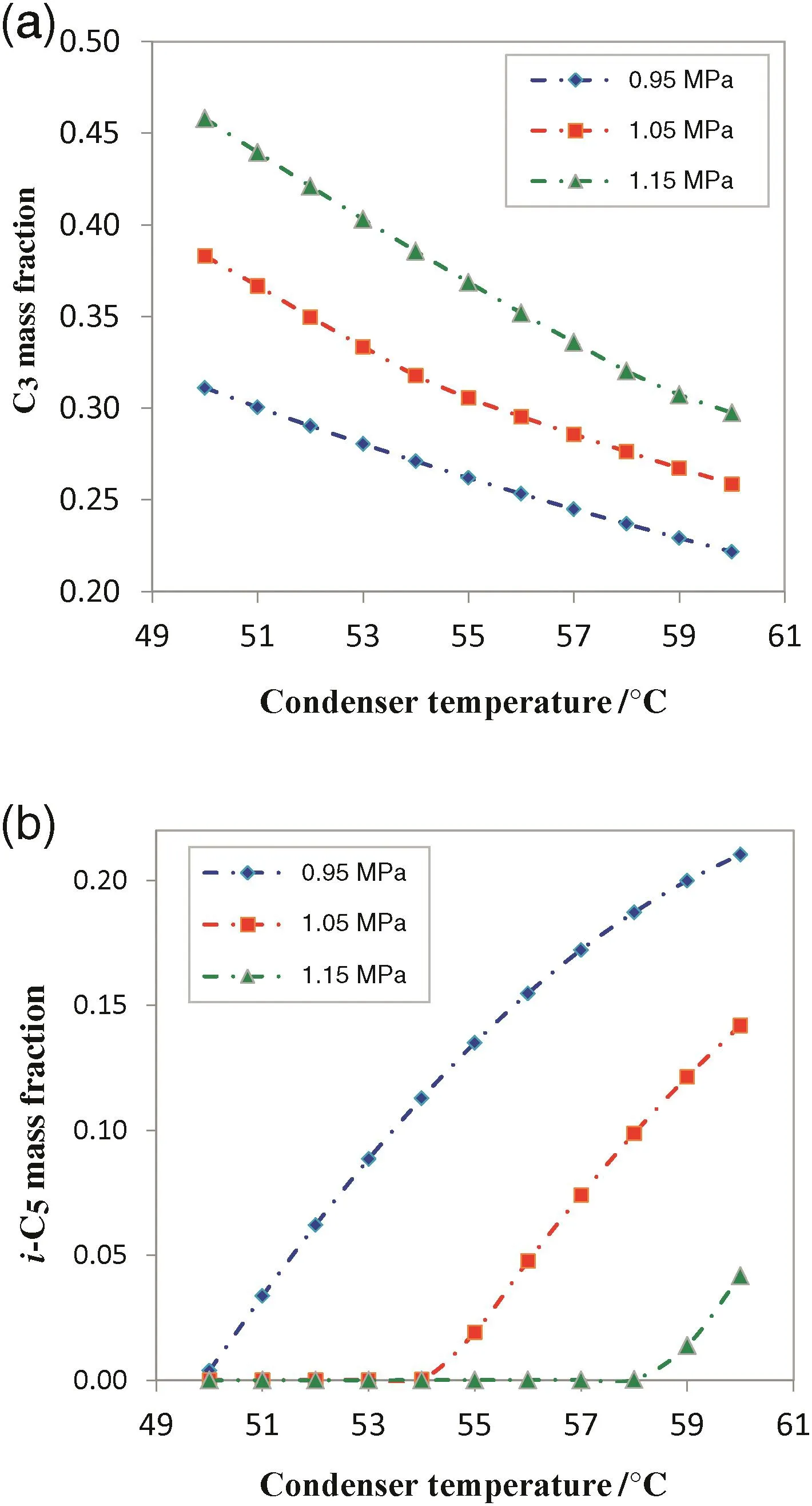
Fig.7.Variations of(a)propane and(b)iso-pentane versus condenser temperature in different pressures.
4.3.Optimization section
In order to maintain the operational pressure(1.05 MPa)at top stage of DBT in hot seasons,an extra heat exchanger for further cooling of the reflux stream is suggested(preferably an air cooler due to its low power consumption).Therefore,an optimized temperature for the reflux stream should be chosen so the stabilization unit can operate at its optimum conditions.Fig.8 indicates the composition of C3versus i-C5for the LPG stream at different temperatures.By taking into consideration the previously mentioned criteria for the LPG compositions(C3between 25%and 37%,andi-C5lower than 2%),the temperature range at the operational pressure may not exceed more than 55°C and surely will not be lower than 51°C.To find the optimum temperature in this range,the production rate of LPGversusNGL is plotted in Fig.9.According to this figure,by considering the reverse relationship in NGL and LPG production,as the temperature goes down the production of LPG decreases mildly;while,this decrement slightly increases the production of NGL.For instance,1 °C drop in the temperature,(from 56 °C to 55 °C)will reduce the overall LPG production by 2.5%;whereas,NGL molar flow will increase less than 0.3%.It is needless to say that the higher production of LPG as one of the main products and obtaining the standard range for LPG component as the plant criteria,are the most important factors to optimize the stabilization unit performance.Therefore,by considering the acquired results from Fig.8,the optimum temperature will be 55°C at the selected operational pressure.The overall production of LPG at this temperature is about 78 t per day plus an average value of 5 t per day LPG flaring which has been prevented by lowering the upstream pressure.Consequently,by saving 5 t per day LPG from flaring(750 t per five hot months in overall)and loosing 2 t per day due to temperature reduction in condenser outlet temperature,a net increase of 450 t in LPG production rate was obtained during five hot months of the year(assuming average of 150 hot days per every year).In addition to the financial loss imposed on the system,LPG flaring has an irreparable effect on environment by emitting about 0.54 t CO2to the atmosphere per 1 t of LPG[23].Hence,81 t of CO2are sent to the atmosphere during five hot months of the year.By comparing the obtained results from the simulation with actual field data presented in Table 2,a slight rise around 4%in LPG final production is detectable.
4.4.LPG fl aring rate and economical estimation
Fig.10 reveals the amount of LPG flaring rate from stabilization unit at abnormal conditions.As mentioned earlier,due to the reduction in air cooler efficiency,the gradual enhancement in condenser outlet temperature of the debutanizer tower can lead to increase the pressure parameter at top stages of the tower.At operating pressure of 1.15 MPa,the control systems of the column are activated to control the tower pressure by LPG flaring.In this industrial stabilization unit,when the tower pressure increases to 1.25 MPa,then total failing occurs in the cooling system,the whole unit becomes out of service,and LPG production stops.In this situation,NGL continues its path to the emergency gas condensate stabilization unit which is clear in Fig.10.It should be considered that both the flaring and LPG flow rates reported in Fig.10 are momentary.In order to perform an accurate statistic for LPG flaring specially,during five hot months of the year in south of Iran, flaring data values from PCV-114 were measured from May to October months by considering 3 h daily effective LPG flaring.The data are plotted in Fig.11.This figure shows a perfect consistency between the simulation results and the actual data of plant.Consequently,the economical estimation can be performed.It must be noticed that the operating values drew in Fig.11 were recorded daily and at the maximum pressure of the column.According to the Gold Persian Fob criterion,the accepted price for a ton of LPG is 800USD in 2014.From an economical point of view and based on the mentioned criterion,about 2400USD equivalent LPG product is sent to flare daily.According to the LPG price and the amount of CO2emission due to LPG flaring,360000USD of LPG product burns in flare system and 81 t of CO2is sent to the atmosphere during five hot months of the year.As a result,the improvement of cooling system of DBT and reducing the fluid outlet temperature of the condenser as a definitive and profitable method should be considered carefully.Therefore,in the present study,after applying modifications,about 750 t of LPG product was saved from flaring during five hot months of the year,which resulted in 360000USD extra annual income for the company.Also,from environmental point of view,this optimization caused to reduce 81 t per year of CO2emission(the most effective Greenhouse gas)to the atmosphere that is benefit for the society.
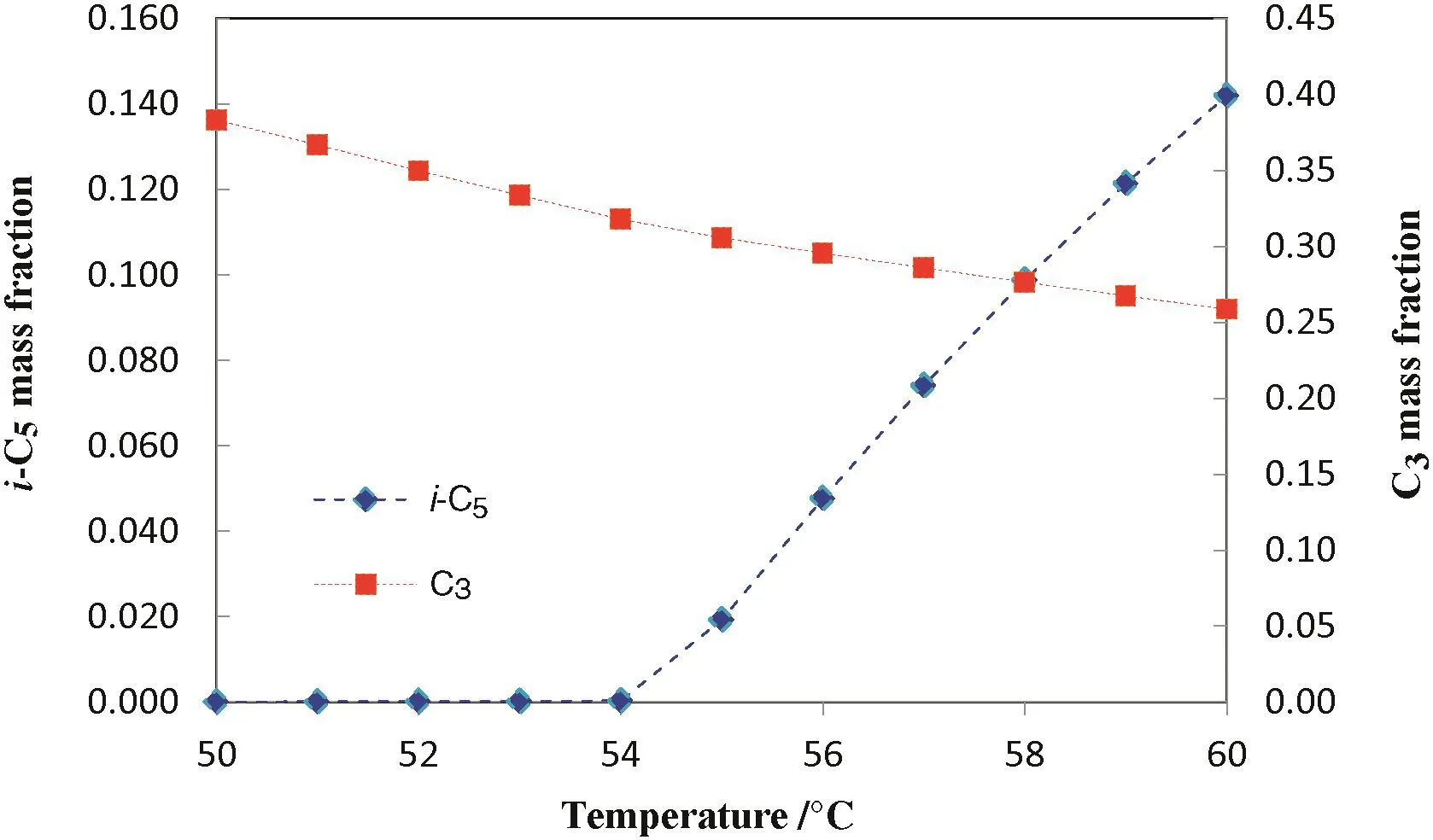
Fig.8.Mass composition of C3 and i-C5 versus temperature on LPG stream at operational pressure(1.05 MPa).

Fig.9.Mass flow rate of LPG and NGL versus temperature at operational pressure(1.05 MPa).
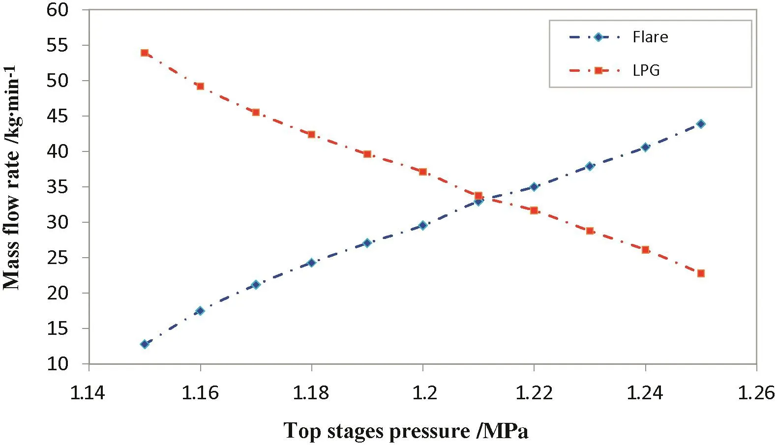
Fig.10.The amount of LPG flaring rate from stabilization unit at abnormal conditions.
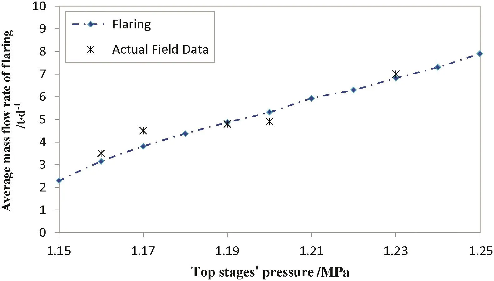
Fig.11.LPG flaring from S-702 in different ranges of pressure.
5.Conclusions
The main purpose of the present study was to perform a reliable simulation of a stabilization unit in order to carry out a sensitivity analysis on the most important parameters of the unit including LPG and NGL production rate and the composition of the produced LPG.Hence,the existing relationship between these parameters and other operational variables like condenser heat duty of the debutanizer tower andetc.,was discovered.According to the simulation results,the unit was not operational under its optimum conditions during the summer.By reduction of DBT temperature,its pressure was decreased and the amount of LPG flaring through the top of the tower decreased respectively.Besides,the simulation results ascertained that by applying the new scheme in hot seasons,the reflux stream temperature approached the value of approximately 55°C which caused an efficient increment of about 4%in LPG production.Moreover,the produced NGL slightly decreased and the consumed amount of fuel gas in the tower reboiler decreased as well.In addition,after some modifications,an increase of about450 tin LPG production rate was obtained during five hot months of the year.Hence the company seemed to be successful in earning 360000USD extra annual income.
Interestingly,in present investigation,by applying an accurate modification and optimization,the CO2emission to the atmosphere decreased almost 81 t.Therefore,from an environmental perspective the current study revealed some positive points which unquestionably,must be considered by decision makers particularly,those who care about ecosystem and healthy life.
[1]J.M.Campbell,Gas conditioning and processing,the basic principles,nineth ed.John M.Campbell/PetroSkills(2014),Norman,2014.
[2]S.Mokhatab,A.W.Poe,J.G.Speight,Hand book of natural gas transmission and processing,Gulf professional publishing,2006.
[3]D.M.Himmelblau,T.F.Edgar,L.S.Ladson,Optimization of chemical processes,second ed.McGraw-Hill Inc.,2001.
[4]K.Salehi,S.M.Jokar,J.Shariati,M.Bahmani,M.A.Sedghamiz,M.R.Rahimpour,Enhancement of CO conversion in a novel slurry bubble column reactor for methanol synthesis,J.Nat.Gas Sci.Eng.21(2014)170–183.
[5]H.Z.Kister,What causes malfunctions in refinery towers,Hydrocarbon Asia,2002.
[6]J.F.Canete,S.Gonzalez-Perez,P.Saz-Orosco,Artificial neural network identification and control of a lab-scale distillation column using LABVIEW,World Acad.Sci.Eng.Technol.2(2008)11–28.
[7]R.M.Ansari,M.O.Tade,Nonlinear model based multivariable control of a debutanizer,J.Process Control8(1998)279–286.
[8]J.Fernandez de Canete,A.Garcia-Cerezo,I.Garcia-Moral,P.Del Saz,E.Ocho,Object oriented approach applied to ANFIS modeling and control of a distillation column,Expert Syst.Appl.40(2013)5648–5660.
[9]M.Davoudi,A.Aleghafouri,A.Safadoost,Flaring networks assessment in South Pars Gas processing plant,J.Nat.Gas Sci.Eng.21(2014)221–229.
[10]A.Nemati Rouzbahani,M.Bahmani,J.Shariati,T.Tohidian,M.R.Rahimpour,Simulation,optimization,and sensitivity analysis of a natural gas dehydration unit,J.Nat.Gas Sci.Eng.21(2014)159–169.
[11]M.Amidpour,M.H.Hamedi,M.Mafi,B.Ghorbani,R.Shirmohammadi,M.Salimi,Sensitivity analysis,economic optimization,and con figuration design of mixed refrigerant cycles by NLP techniques,J.Nat.Gas Sci.Eng.24(2015)144–155.
[12]S.A.Al-Sobhi,A.Elkamel,Simulation and optimization of natural gas processing and production network consisting of LNG,GTL,and methanol facilities,J.Nat.Gas Sci.Eng.23(2015)500–508.
[13]M.Davoudi,M.R.Rahimpour,S.M.Jokar,F.Nikbakht,H.Abbasfard,The major sources of gas flaring and air contamination in the natural gas processing plants:A case study,J.Nat.Gas Sci.Eng.13(2013)7–19.
[14]R.K.Abdulrahman,I.M.Sebastine,Natural gas sweetening process simulation and optimization:A case study of Khurmala field in Iraqi Kurdistan region,J.Nat.Gas Sci.Eng.14(2013)116–120.
[15]M.Bassyouni,u.H.SW,A.-A.MH,A.-h.SM-S,N.SH,N.A.F,Date palm waste gasification in down draft gasifier and simulation using ASPEN HYSYS,Energy Convers.Manag.88(2014)693–699.
[16]M.Shariq Khan,Y.Donald Chaniago,M.Getu,M.Lee,Energy saving opportunities in integrated NGL/LNG schemes exploiting:Thermal-coupling common-utilities and process knowledge,Chem.Eng.Process.Intens.82(2014)54–64.
[17]H.Z.Kister,Distillation operation,McGraw-Hill Inc.,New York,1990.
[18]J.P.Wauquier,Petroleum refining.separation processes,Editions Technip.2000.
[19]E.E.Ludwig,Applied process design for chemical and petrochemical plants,third ed.Gulf Publishing,1995.
[20]P.Xu,S.Xu,H.Yin,Application of self-organizing competitive neural network in fault diagnosis of suck rod pumping system,J.Pet.Sci.Eng.58(2006)43–48.
[21]S.M.Babakhani,M.Bahmani,J.Shariati,K.Badr,Y.Balouchi,Comparing the capability of artificial neural network(ANN)and CSMHYD program for predicting of hydrate formation pressure in binary mixtures,J.Pet.Sci.Eng.136(2015)78–87.
[22]N.A.Darwish,N.Hilal,Sensitivity analysis and faults diagnosis using artificial neural networks in natural gas TEG-dehydration plants,Chem.Eng.J.137(2008)189–197.
[23]Y.Shu,N.S.N.Lam,M.Reams,A new method for estimating carbon dioxide emissions from transportation at fine spatial scales,J.Environ.Res.Lett.5(2010)(9 pp.).
 Chinese Journal of Chemical Engineering2017年3期
- Chinese Journal of Chemical Engineering的其它文章
- A novel green inhibitor for C-steel corrosion in 2.0 mol·L−1 hydrochloric acid solution
- An ecofriendly approach for corrosion control of 6061 Al-15%(v)SiC(P)composite and its base alloy
- Polymorphism of D-mannitol:Crystal structure and the crystal growth mechanism☆
- Bulk and bubble-scale experimental studies of influence of nanoparticles on foam stability
- Efficient decolorization of dye-containing wastewater using mycelial pellets formed of marine-derived Aspergillus niger☆
- Characterization of pyrolytic lignins with different activities obtained from bio-oil☆