Energy-Efficient Mobile Data Collection Adopting Node Cooperation in an Underwater Acoustic Sensor Network
Yougan Chen, Xiaoting Jin, Xiaomei Xu
1 Key Laboratory of Underwater Acoustic Communication and Marine Information Technology (Xiamen University),Ministry of Education, Xiamen 361005, China
2 Department of Applied Ocean Physics and Engineering, Xiamen University, Xiamen 361102, China
* The corresponding author, email: xmxu@xmu.edu.cn
I. INTRODUCTION
Underwater acoustic sensor networks (UWASNs) have become a promising research area because of their widespread applications including underwater environment monitoring and tactical surveillance [1–4]. One research issue is to design effective approaches for one central sensor node to collect the data from multiple underwater sensors [5-7].
For the UW-ASNs, the underwater nodes are usually battery-powered; as a result, it is not simply the power, but the energy consumption that matters [8], especially for longterm observation. To address this challenge,numerous protocols have been proposed to save energy for the UW-ASNs [9–14], including adaptive modulation and coding, optimizing MAC protocol, cross-layer routing design and MIMO-OFDM et al, which can be classified into two types for energy saving: increasing the transmitting bit rate and minimizing the number of retransmissions. Recently,cooperative transmission is used in wireless ad hoc networks to increase energy efficiency by allowing packets to be delivered over several short links [15–17]. Transmitter-cooperation strategies adopting coding have been proposed to improve the system performance in underwater channels [18–21]. The adaptive network coded cooperation [22] and the generalized adaptive network coded cooperation [23] are especially appealing for a data collection network, where the coding structure matches well with the underlying network topology. This work is based on ahomogeneousnetwork [22,23], where the cooperation schedule is predetermined and all nodes are participating in the cooperation phase. Furthermore, we have proposed selective relay cooperation (SRC) and dynamic network coded cooperation (DNC)in [24] for UW-ASNs with the framework of aheterogeneousnetwork, where the individual sensor nodes may have quite different channel characteristics and hence not all the sensor nodes are good candidates for relay cooperation. Yet the network considered in [24] is a one-hop small-scale network with one central coordinator. The example network presented in [24] is that one surface destination node collects data from 3 to 5 underwater nodes.
In this paper, we consider a middle-scale network for underwater data collection, which is essentially a multi-hop or distributed network. The example network in Section III is that one surface destination node collects data from 14 underwater nodes. Therefore, the surface destination node needs to be working in a mobile collection way.
The authors proposed a practical node cooperation protocol for a middle-scale UWASN with one mobile surface node to collect data from multiple underwater nodes.
Specifically, the main contributions of this paper are as follows.
--Cooperative communication is proposed for underwater mobile data collection. To collect underwater data in the middle-scale network, we propose apracticalnode cooperation (NC) protocol applied in the mobile surface node, which could switch adaptively between SRC protocol and DNC protocol according to the underwater acoustic channel.The proposed protocol is easy to implement in practice.
--Energy-efficient issues are considered during the mobile cooperation design. To reduce the source level of underwater nodes,the data collection area is divided into several sub-zones. The rules of collection division and cooperative zone design are studied for energy saving.
Note that the use of mobile autonomous underwater vehicle (AUV) equipped with an acoustic modem to gather data from underwater nodes has been studied in [25]. However it doesn’t consider the cooperative communications.
The rest of this paper is organized as follows. Section II outlines the network and channel models. Section III gives the detailed procedure of the proposed scheme. Simulation results are provided in Section IV. Finally,Section V concludes the paper.
II. NETWORK AND CHANNEL MODELS FOR UNDERWATER ACOUSTIC DATACOLLECTION
2.1 Network model for mobile data collection
To illustrate an underwater acoustic data collection network, we assume that there areNubottom sensor nodes which sample environmental parameters on their own schedule and transmit the data to the surface buoy periodically through acoustic links, as shown in Fig. 1. Finally the data will be sent to a data center through a wireless radio link. The surface buoy is often powered from the mother vessel and all the attached units can be always on. The acoustic modems on the bottom nodes are in a sleep mode before being triggered.The surface node can obtain the distances of the sensor nodes to the destination during the deployment or measuring through the ranging function of the modems.
In particular, the main differences between this paper and [24] are as follows.
-- Network Scale. The network in [24] is a one-hop small-scale network with one central coordinator, which has only 3~5 underwater nodes. We consider a middle-scale network in this paper, which has 14 underwater nodes in the next example. Therefore, the surface destination node needs to be working in a mobile collection way.
-- Node Cooperation Style. The node cooperation in [24] is adopting the SRC protocol or the DNC protocol separately. Yet in this paper,as the surface node works in a mobile way, it could switch between SRC and DNC according to underwater environment dynamically,which is more practical for mobile data collection in the middle-scale underwater network.And the NC protocol is easy to implement in practice.
-- Energy-efficient Issues. The energy consumption issues are considered during the mobile cooperation design. Specifically, the data collection area division, the rules of non-cooperative index and cooperative zone design are studied for energy saving.
2.2 Underwater acoustic channel and energy consumption model
The passive sonar equation can be used to describe the signal-to-noise ratio (SNR) measured at the destination [26]:

whereSL,TL,NLandDIin dB, are the source level, transmission loss, noise level and directivity index respectively. As we assume omnidirectional hydrophones and thus the directivity index is set to 0. The transmission loss for an acoustic signal with transmission distancedin meter and frequencyfin kHz is given by

which can be described in dB as follows

whereκis the spreading factor caused by energy spreading. Commonly we consider a practical spreading factorκ=1.5.is the absorption coefficient in dB/km, which depends on the signal frequency and can be expressed empirically by Thorp’s formula [26, 27] :
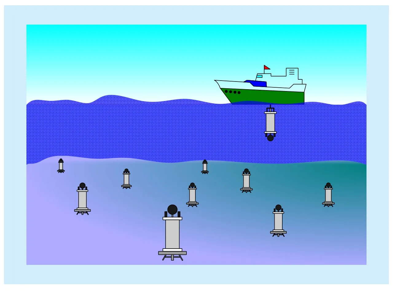
Fig. 1 An example network with one mobile surface node to collect data from multiple underwater nodes

withfin kHz.
For underwater acoustic channels, the ambient noise is modeled by four components:turbulence, shipping, waves and thermal noise.Gaussian statistics and a continuous power spectral density (p.s.d.) can be used to describe most of the ambient noise sources. The p.s.d. of the four noise components in dB re μPaper Hz as a function of frequency in kHz is given by following empirical formulae [28]:
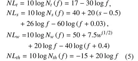
wheresis the shipping activity factor, whose value ranges between 0 and 1 for low and high activity, respectively;wis the wind speed in m/s. If we definethen the overall noise can be calculated as

described in dB as following

For using acoustic waves, the sound intensity of a source is related to the transmitted signal intensityItand a reference intensityIrefas given in the following equation

In the case of cylindrical spreading, the transmission powerPtin watt required to achieve intensityItat 1m from the source in the direction of the receiver is obtained through the following expression

wherePtin watt andzis the depth in meter.
For commercial hydrophones [29], the energy needed to receive a packet is typically around one fifth of the transmitted energy.Therefore, the energies to transmit and receive a packet oflbits at a bit ratebbps are computed as follows

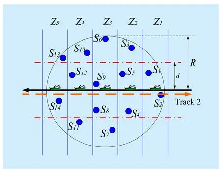
Fig. 2 Collection track and area division for mobile data collection
whereTtis the duration time for transmittinglbits in s.
III. NODE COOPERATION FOR MOBILE UNDERWATER ACOUSTIC DATA COLLECTION
Fig. 2 presents an example network with 14 underwater sensor nodes for the mobile surface node to collect data. There is no collaboration among the sensor nodes in the conventional ARQ scheme. In fact, due to the broadcast nature, one node’s transmission to the destination can be overheard by other nodes,which make the cooperation with each other possible for the underwater sensor nodes. In the following section, we will introduce the cooperative protocols that can improve the mobile collection efficiency through relay on sensor node cooperation.
Before we discuss the proposed node cooperation for the mobile underwater acoustic data collection, here are some assumptions about the mobile data collection system:
-- Middle-Scale Network. The network considered here is a middle-scale network.Then we need to consider the mobile data collection design problem.
-- Low Mobile Velocity. Due to the low speed of underwater acoustic data transmission, the mobile velocity of the surface node for data collection is accordingly set at a relatively low value to decrease the effect of Doppler shift.
-- The Same Depth Deployment. As the distance between any two nodes is much larger than the depth of the sensor nodes’ deployment in the shallow water environment, we ignore the effect of different depth and assume the same depth deployment for simplicity in this paper.
-- Necessary Doppler Compensation.The Doppler shift issue caused by the mobile mother ship for data collection has been solved, and the details of Doppler compensation are beyond the scope of this paper.
3.1 Mobile collection path
Because different collection paths will lead to different energy consumption, the mobile collection path must be designed carefully for energy saving. In this paper, the collection path design follows the rules as bellow:
–For simplicity, the mobile collection path is designed as a straight line.
–With randomly distributed underwater nodes, the mobile collection path must across or around the two sensor nodes with the maximum distance.
–The underwater nodes are distributed uniformly on the two sides of the collection path when possible.
–Make the nodes as close as possible to the mobile path, which will relay the other nodes far away easily.
–If repeat-request for mobile collection is needed, the repeat-mobile collection will retrace the track.
Fig. 2 shows an example of the mobile collection path.
3.2 Collection area division and cooperative zone
Since we consider a middle-scale network, to reduce the source level and increase the efficiency, we can divide the data collection area into several sub-zones. Fig. 2 is an example of network with 5 sub-zones, and Fig. 3 shows the example with 3 sub-zones.
On the other hand, to control the source level and ensure the cooperation, we must consider the transmission level over the distancedin the non-cooperative zone.
Definition 1.As shown in Fig. 2, the zone between ±dis called asnon-cooperative zone,which means the nodes located in this zone can be decoded accurately by the destination,and the area beyond this is called ascooperative zone.
To describe the cooperative level, we defineas the non-cooperative index,

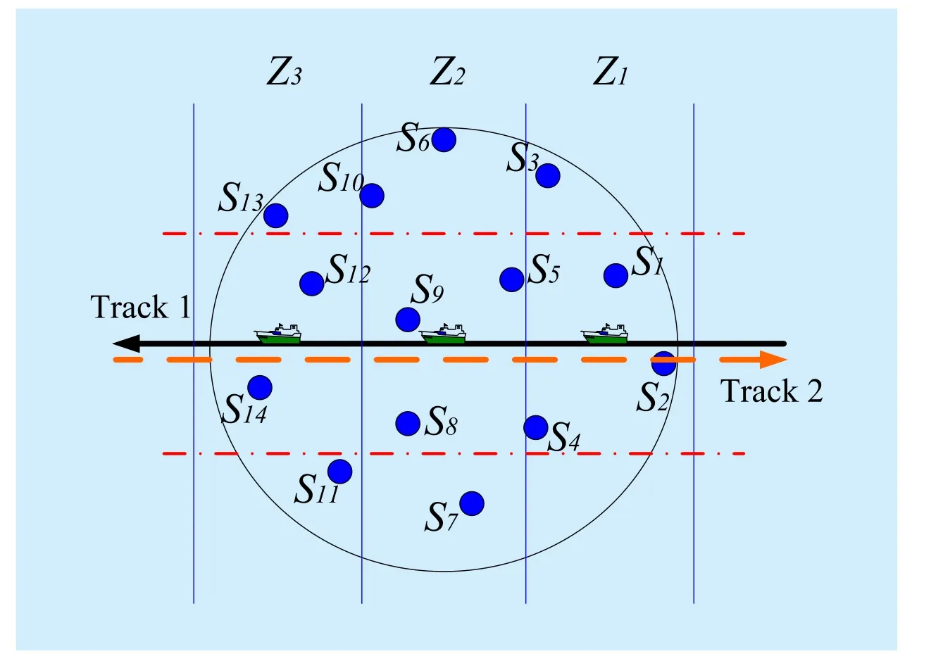
Fig. 3 An example of network division for 3 sub-zones
whereRis the radius of the example network area. With larger, it means powerful source level is needed. Yet the smallermust ensure the destination can decode the data accurately.In the next, we will present how to find the minimum
Denoterias the distance from the nearest neighbor node to node Si. With the assumption that the receiver can decode the data from node Siaccurately over the distanceri, to ensure the cooperation happen, the minimum distancedminfor the overall system is as

Therefore, we have the minimum non-cooperative index as

3.3 Node cooperation protocol
3.3.1 ARQ, SRC and DNC protocols
The conventional ARQ protocol is illustrated in Fig. 4(a). To collect the data fromNuunderwater nodes, the destination will first send a request to all the underwater nodes including a collection schedule, and then all theNunodes send the data packets to the destination in turn.
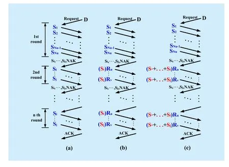
Fig. 4 Different protocols for data collection: (a) Conventional ARQ; (b) Selective relay cooperation (SRC); (c) Dynamic network coded cooperation (DNC)
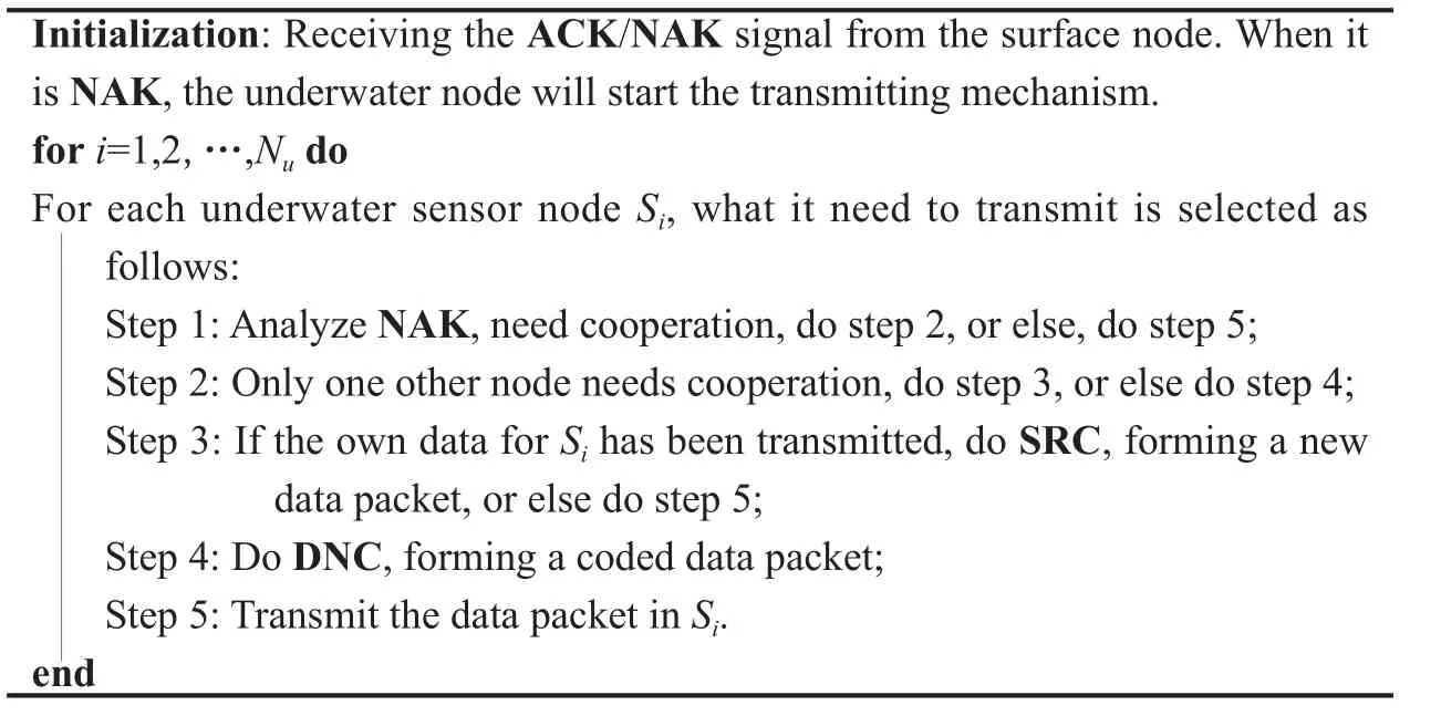
Algorithm 1: Node Working Mechanism Algorithm
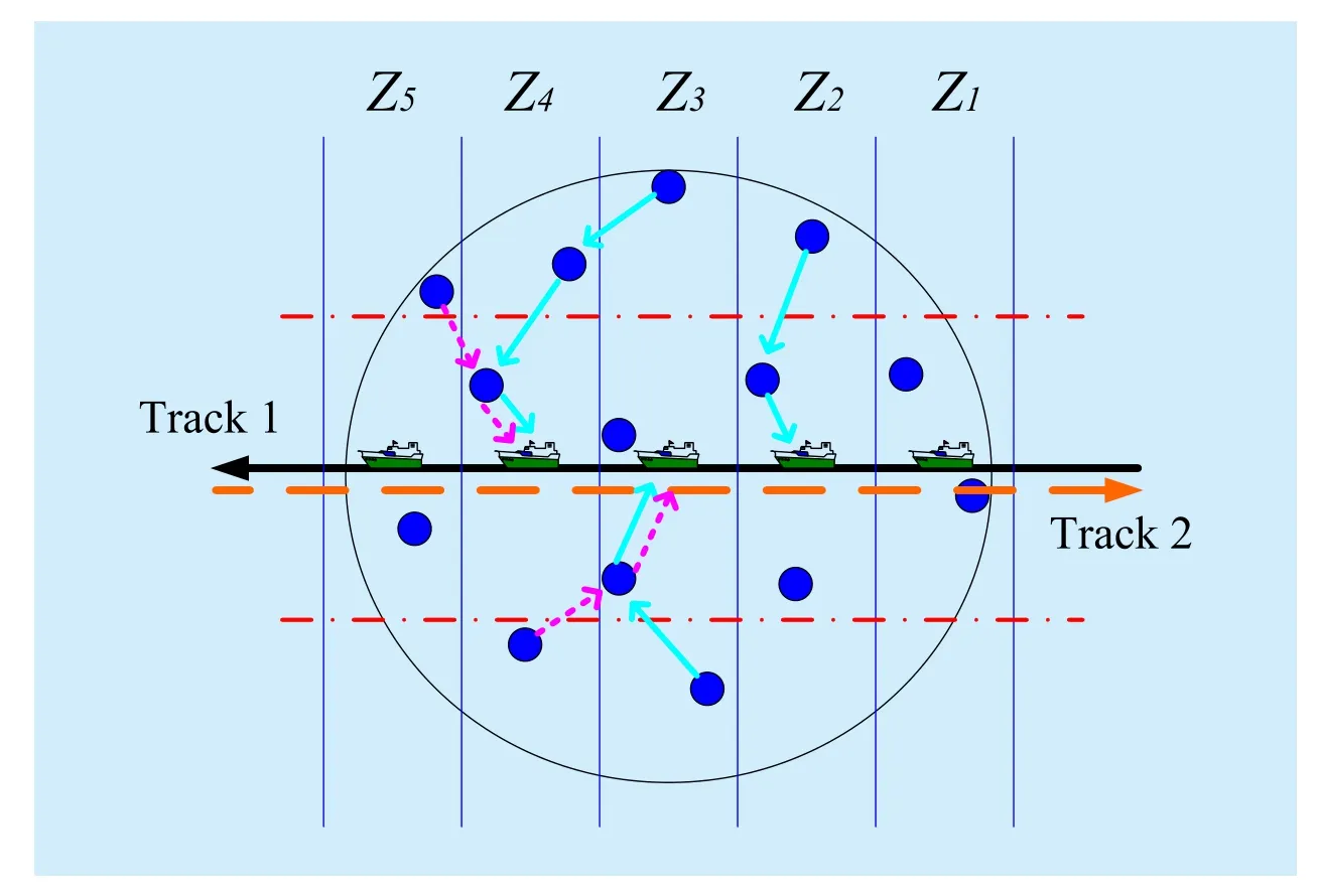
Fig. 5 An example cooperative route for network with 5 sub-zones
After decoding at the destination, the destination will request another round of transmission for those nodes with decoding failures,saySitoSjas shown in Fig. 4(a). Then, the corresponding nodes will send another transmission, where the retransmitted packet could be identical to the original packet as in the type-I ARQ protocol, or could be a different packet with additional parity check bits as in the type-II ARQ protocol. This procedure repeats until the destination collects the data from all the nodes successfully or a maximum round of transmissions is reached.
We have proposed selective relay cooperation (SRC) and dynamic network coded cooperation (DNC) protocols in [24]. In the SRC protocol as shown in Fig. 4(b), instead of retransmission by the undecoded node itself,another node that has overheard the transmission successfully and has a better channel condition will be selected as a relay. In the DNC protocol as shown in Fig. 4(c), each selected relay node transmits a network coded packet combining the overheard data from several undecoded nodes. The cooperation schedules are optimized at each transmission round by the central control node based on the collected information, especially the channel quality as reported by the physical layer.
More design details of SRC protocol, DNC protocol, and the filed test results can be found in [24].
3.3.2 Node working mechanism
In each sub-zone, the node cooperation protocol adopting for the mobile surface node could switch adaptively between SRC protocol and DNC protocol. Furthermore, the NC protocol could also be applied across sub-zones due to the wiretap property.
The node working mechanism algorithm is summarized in Algorithm 1. Fig. 5 presents an example of cooperative route for the network with 5 sub-zones.
IV. NUMERICAL RESULTS
4.1 Simulation setup
Although the protocols are compatible with other modulation schemes, we use the OFDM modulation in simulation. Letsube theK×1 vector containing the transmitted symbols on the OFDM subcarriers for nodeu, andzube the frequency-domain measurement at destination after necessary Doppler compensation and FFT operation [30]. The input-output relationship from theuth node to the destination is

whereHudenotes the channel mixing matrix with sizeK×K, andwuis the ambient noise at the receiver with lengthK×1. When the channel is time-invariant,Huis diagonal, otherwise, inter-carrier-interference (ICI) occurs and some off-diagonal components of eachHuare nonzero. The OFDM parameters are chosen as in [31], with the number of OFDM subcarrierK= 1024.
We use one specific geographical topology as shown in Fig. 5 to conduct simulations,where there are 14 underwater sensor nodes in a two-dimensional area of circle to collect and report the data from the environment to the surface mobile ship. The area is divided into five sub-zones along the vertical diameter. The relative coordinate for each underwater sensor node in a plane Cartesian coordinate system are shown in Table 1. All the sensor nodes are deployed underwater 30 m.
The shipping activity factor and wind speed in the underwater noise model ares= 0.5 andw= 10 m/s, respectively. The multipath channels are randomly generated with 50 taps in the baseband, and are assumed as quasi-static fading.
4.2 Simulation results
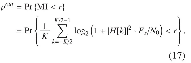
Instead of a practical code, here we assume capacity-achieving codes and use the mutual information (MI) to evaluate the outage probabilities of whether a packet can be decoded correctly at the receiver. For the node-to-node transmission withKOFDM sub-carrier, the MI is as

An outage occurs if the total mutual infor-mation at the destination after the dynamic coded cooperation is lower than the information rater, which is as
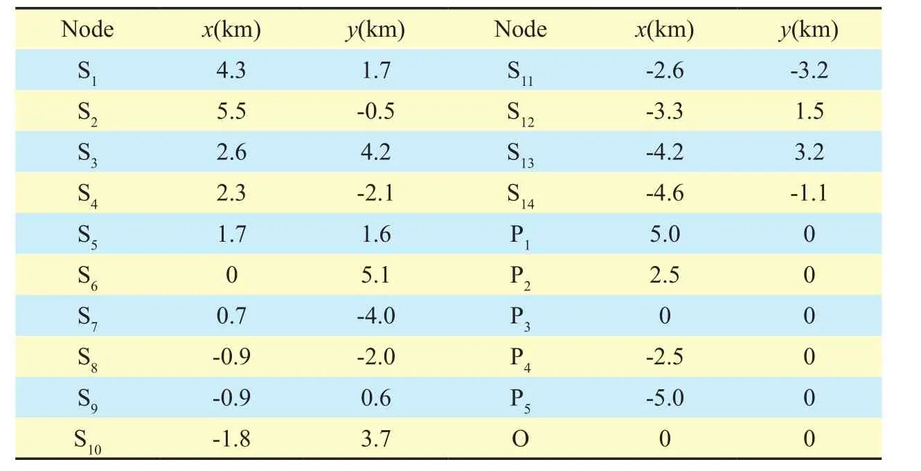
Table I The coordinate for each underwater sensor node in a plane Cartesian coordinate system
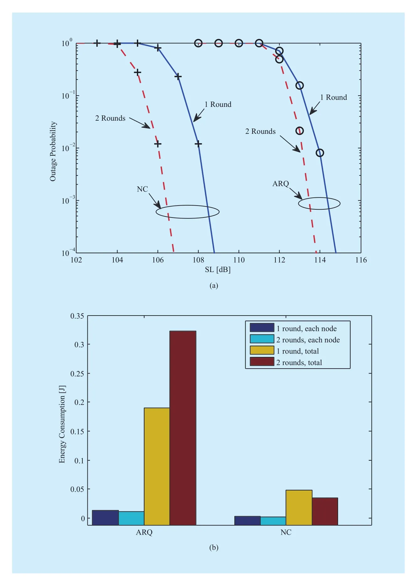
Fig. 6 The system performances of the two schemes: (a) the system outage probability; (b) the energy consumption
We set the information rate as 0.5 bit/symbol in the simulation.
As a figure of merit, we evaluate the overall system performance concerning all the 14 nodes. Only when the surface node collects the data from all the nodes correctly, the data collection procedure is regarded as successful,otherwise an outage is declared, i.e.,
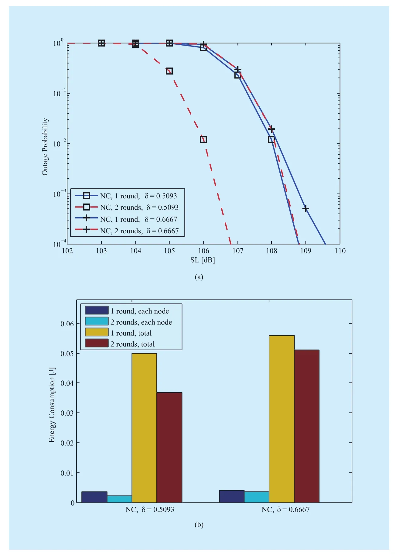
Fig. 7 Performances of different non-cooperative index: (a) the outage probability; (b) the energy consumptions comparison

Fig. 6(a) demonstrates the simulated outage probabilities of two strategies. We can see that the NC scheme has about 6 dB gain compared with the conventional ARQ with one round.For both schemes, using two rounds collection achieves better outage performance. For the ARQ scheme, using two rounds collection leads to additional 0.8 dB gain compared with only one round. The NC scheme is better than the ARQ scheme with two rounds collection,which bringing additional 2 dB gain. This is because the NC scheme exist cooperative operation among underwater nodes and can get more benefit. However, the ARQ scheme relies on the individual path to the sink for each node, i.e., the packet is transmitted without considering the other nodes. Thus, more retransmissions and energy consumption are required for the farthest node in the ARQ scheme.
Fig. 6(b) depicts the average minimum energy of each node and all nodes required to reach a given performance of outage probabilitypout≤ 10-3. We can find that the total energy consumption in the case of the NC scheme is considerably smaller than those in the ARQ scheme. This is because the NC scheme improves the possibility of receiving packets successfully by forwarding the packets through multiple paths, leading to fewer retransmissions, especially in the case of switching to the DNC protocol. Thus, the packet reaches the destination with a lower transmitter power in this case. On the other hand, although the outage probability improves with more rounds as shown in Fig. 6(a), the energy consumption of two rounds is lower than one round for each node in both ARQ and NC schemes in Fig.6(b). Moreover, the total energy consumption of two rounds is slightly lower than one round for the NC scheme, resulting from its outage probability improving apparently with two rounds. It implies that more rounds are better for the NC scheme to improve energy efficiency, as it can cooperate with each other more intensively.
To quantify the effect of non-cooperative index in the proposed scheme, the outage probability with different value of the non-cooperative index is plotted in Fig. 7(a),From Fig. 7(a), we have the following observations. The outage probability performance becomes worse when the non-cooperative indexincreases. Forusing two rounds brings additional 2 dB gain compared with using one round. Yet for, this benefit from the additional rounds decreases to less than 0.5 dB. This implies that the distance of one or more nodes to the nearest neighbor node becomes further with the non-cooperative indexincreasing. The channel quality which is affected by distance becomes worse. Therefore,it is hard to find cooperative nodes for this or these nodes.
Fig. 7(b) shows the energy consumption relative to different values of non-cooperative index. Note that the difference of the total energy consumption between two rounds and one round becomes smaller. The reason is that, with a higher non-cooperative index, the source level must be set higher accordingly.
With different collection area division, the distance between nodes is invariant. Fig. 8(a)shows the overall outage probability of three sub-zones and five sub-zones with one and two rounds, where adopting three sub-zones has about 1 dB gain compared with five subzones with one round. The reason is that dividing less zones means there are more nodes in each zone and the broadcast order may be changed. Hence, nodes in the last zone of one round can find cooperative nodes more easily,e.g. ifS13has failed to send a packet to the sink andS12can decode its data correctly, in the case of five sub-zones, this data need to be sent in the second round. However in the case of three sub-zones this data can be sent byS12in the first round according to the schedule list. On the other hand, the performance of three sub-zones with two rounds is close to that of five sub-zones with two rounds. This is due to the scheme constraint. Furthermore,when changing the number of sub-zones, the outage probability cannot become better for the two rounds case. From Fig. 8(b), it can be observed that adopting three zones has lower energy consumption and it is not sensitive to collection rounds. This result is consistent with that in Fig. 8(a).
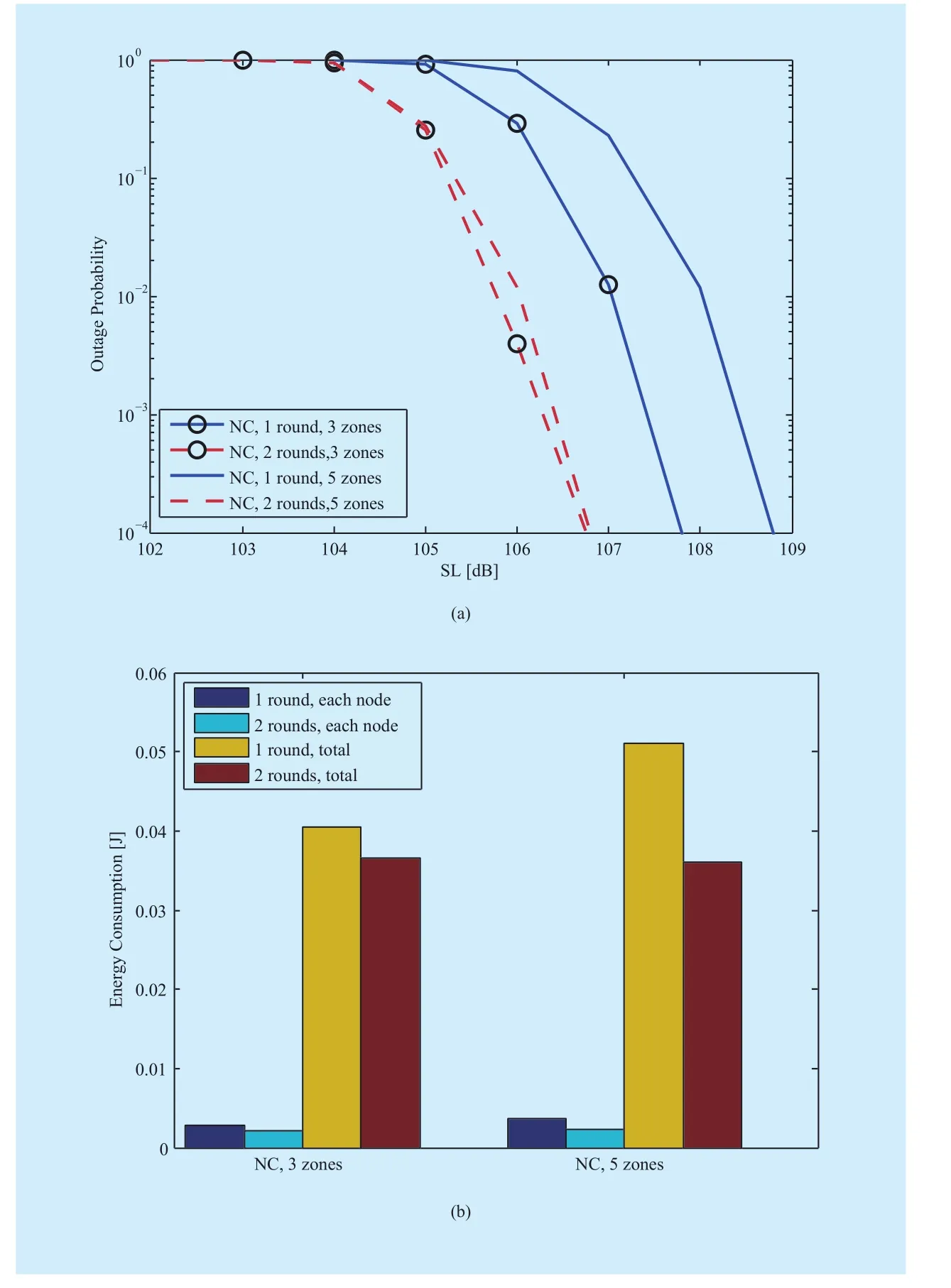
Fig. 8 Performances of different collection area divisions: (a) the outage probability; (b) the energy consumptions comparison
V. CONCLUSIONS
In this paper, we proposed apracticalnode cooperation protocol for a middle-scale UWASN with one mobile surface node to collect data from multiple underwater nodes. Compared with the conventional ARQ protocol,numerical results show that the proposed NC protocol can improve the system performance significantly.
In our future work, we will investigate the real-time processing for the mobile underwater acoustic data collection system.
ACKNOWLEDGEMENTS
The authors would like to thank the reviewers for their detailed reviews and constructive comments, which have helped improve the quality of this paper. We thank Dr. Shengli Zhou from University of Connecticut for his suggestions on the manuscript. This work was supported in part by National Key Research and Development Program of China under Grants No. 2016YFC1400200 and 2016YFC1400204, National Natural Science Foundation of China under Grants No.41476026, 41676024 and 41376040 and Fundamental Research Funds for the Central Universities of China under Grant No.220720140506.
[1] E. M. Sozer, M. Stojanovic, and J. G. Proakis,“Underwater acoustic networks,”IEEE Journal of Oceanic Engineering, vol. 25, no. 1, pp. 72-83,2000.
[2] J.-H. Cui, J. Kong, M. Gerla, andet al, “The challenges of building mobile underwater wireless networks for aquatic applications,”IEEE Network, vol. 20, no. 3, pp. 12-18, 2006.
[3] M. Erol-Kantarci, H. T. Mouftah, and S. Oktug,“A survey of architectures and localization techniques for underwater acoustic sensor networks,”IEEE Communications Surveys & Tutorials, vol. 13, no. 3, pp. 487-502, 2011.
[4] H. Chen, G. Fan, L. Xie, andet al, “A Hybrid Path-Oriented Code Assignment CDMA-Based MAC Protocol for Underwater Acoustic Sensor Networks,”Sensors,vol. 13, no. 11, pp. 15006-15025, 2013.
[5] W. Alsalih, H. Hassanein, and S. Akl, “Placement of multiple mobile data collectors in underwater acoustic sensor networks,”Wireless Communications and Mobile Computing,vol. 8, no. 8,pp. 1011-1022, 2008.
[6] P. Zheng, H. Mo, J. Liu, andet al, “A networked acoustic modem system for underwater applications,” In Proc. of MTS/IEEE OCEANS Conf.,KONA, 19-22 Sept. 2011
[7] L. Wan, H. Zhou, D. Wilson, andet al, “Analysis of underwater OFDM performance during a two-month deployment in Chesapeake Bay,”Marine Technology Society Journal,vol. 48, no.6, pp. 52-64, 2014.
[8] M. Stojanovic, and J. Preisig, “Underwater acoustic communication channels: Propagation models and statistical characterization,”IEEE Communications Magazine, vol. 47, no. 1, pp.84-89, 2009.
[9] M. K. Park, and V. Rodoplu, “UWAN-MAC: An energy-efficient MAC protocol for underwater acoustic wireless sensor networks,”IEEE Journal of Oceanic Engineering,vol. 32, no. 3, pp. 710-720, 2007.
[10] M. Zorzi, P. Casari, N. Baldo, andet al,“Energy-efficient routing schemes for underwater acoustic networks,”IEEE Journal on Selected Areas in Communications, vol. 26, no. 9, 1754-1766, 2008.
[11] L. C. Kuo, and T. Melodia, “Cross-layer routing on MIMO-OFDM underwater acoustic links,” In Proc. of2012 9th Annual IEEE Communications Society Conference on Sensor, Mesh and Ad Hoc Communications and Networks (SECON),pp.227-235, 18-21 June 2012.
[12] Y. Dong, and H. Dong, “Simulation study on cross-layer design for energy conservation in underwater acoustic networks,” In Proc. ofIEEE Oceans-San Diego, 23-27 Sept. 2013.
[13] L. Wan, H. Zhou, X. Xu, andet al, “Adaptive modulation and coding for underwater acoustic OFDM,”IEEE Journal of Oceanic Engineering, vo.40, no. 2, pp. 327-336, 2015.
[14] Y. Noh, U. Lee, S. Lee, andet al, “HydroCast:Pressure routing for underwater sensor networks,”IEEE Transactions on Vehicular Technology, vol. 65, no. 1, pp. 333-347, 2016.
[15] J. N. Laneman, D. N. C. Tse, and G. W. Wornell,“Cooperative diversity in wireless networks:Efficient protocols and outage behavior,”IEEE Transactions on Information Theory, vol. 50, no.12, pp. 3062-3080, 2004.
[16] R Madan, N. B. Mehta, A. F. Molisch, andet al,“Energy-efficient cooperative relaying over fading channels with simple relay selection,”IEEE Transactions on Wireless Communications, vol.7, no. 8, pp. 3013-3025, 2008.
[17] D. R. Brown, and F. Fazel, “A game theoretic study of energy efficient cooperative wireless networks,”Journal of Communications and Networks, vol. 13, no. 3, pp. 266-276, 2011.
[18] M. Vajapeyam, S. Vedantam, U. Mitra, andet al,“Distributed space–time cooperative schemes for underwater acoustic communications,”IEEE Journal of Oceanic Engineering, vol. 33, no. 4,pp. 489-501, 2008.
[19] P. Wang, L. Zhang, and V. O. K. Li, “Asynchronous cooperative transmission for three-dimensional underwater acoustic networks,”IET Communications, vol. 7, no. 4, pp. 286-294, 2013.
[20] A. M. Jalil, and A. Ghrayeb, “Distributed Channel Coding for Underwater Acoustic Cooperative Networks,”IEEE Transactions on Communications, vol. 62, no. 3, pp. 848-856, 2014.
[21] Y. Chen, Z.-H. Wang, L. Wan, andet al,“OFDM-modulated dynamic coded cooperation in underwater acoustic channels,”IEEE Journal of Oceanic Engineering, vol. 40, no.1, pp. 159-168, 2015.
[22] X. Bao, and J. Li, “Adaptive network coded cooperation (ANCC) for wireless relay networks:matching code-on-graph with network-ongraph,”IEEE Transactions on Wireless Communications, vol. 7, no. 2, pp. 574-583, 2008.
[23] X. Bao, and J. Li, “Generalized adaptive network coded cooperation (GANCC): a unified framework for network coding and channel coding,”IEEE Transactions on Communications, vol. 59,no. 11, pp. 2934-2938, 2011.
[24] Y. Zhang, Y. Chen, S. Zhou, andet al, “Dynamic Node Cooperation in an Underwater Data Collection Network,”IEEE Sensors Journal, vol. 16,no. 11, pp. 4127-4136, 2016.
[25] G. Hollinger, S. Choudhary, P. Qarabaqi, andet al, “Underwater data collection using robotic sensor networks,”IEEE Journal on Selected Areas in Communications, vol. 30, no. 5, pp. 899-911,2012
[26] J. U. Robert, “Principles of underwater sound,”New York: McGraw-Hill Book Company, 1983.
[27] W. H. Thorp, “Analytic Description of the Low-Frequency Attenuation Coefficient,”The Journal of the Acoustical Society of America, vol.42, no. 1, pp. 270-270, 1967.
[28] M. Stojanovic, “On the relationship between capacity and distance in an underwater acoustic communication channel,”ACM SIGMOBILE Mobile Computing and Communications Review,vol. 11, no. 4, pp. 34-43, 2007.
[29] LINKQUEST INC. Underwater acoustic modem.http://www.linkquest.com, 2007.
[30] B. Li, S. Zhou, M. Stojanovic, andet al, “Multicarrier communication over underwater acoustic channels with nonuniform Doppler shifts,”IEEE Journal of Oceanic Engineering, vol. 33, no,2, pp. 198-209, 2008.
[31] H. Yan, L. Wan, S. Zhou, andet al, “DSP based receiver implementation for OFDM acoustic modems,”Physical Communication, vol. 5, no.1,pp. 22-32, 2012.
- China Communications的其它文章
- Robust Blind Separation for MIMO Systems against Channel Mismatch Using Second-Order Cone Programming
- SGuard: A Lightweight SDN Safe-Guard Architecture for DoS Attacks
- Remote Three-Factor Authentication Protocol with Strong Robustness for Multi-Server Environment
- Accessing Alignments of Ontologies via IoT Based on SKOS Data Model
- Digital Rights Management: Model, Technology and Application
- GPP Based Open Cellular Network Towards 5G

