基于FPGA的超声相控阵发射系统设计
杜春晖
(1.中国煤炭科工集团太原研究院有限公司,太原 030051;2.山西天地煤机装备有限公司,太原 030051)
基于FPGA的超声相控阵发射系统设计
杜春晖1,2*
(1.中国煤炭科工集团太原研究院有限公司,太原 030051;2.山西天地煤机装备有限公司,太原 030051)
为使水声成像系统小型化,首创性地提出了将相控阵技术和水下超声成像技术结合在一起,设计了一种基于FPGA的超声相控阵发射系统。对相控聚焦的发射原理进行了分析,利用FPGA的内部逻辑资源和丰富的I/O引脚实现了6通道超声相控阵发射,为有效激励压电换能器设计了信号调理电路对激励信号进行D/A转换及放大。通过实验测试表明,该系统可以实现超声信号的相控发射,相控延时精度达到2.5 ns,发射信号稳定,系统集成度高,为水下超声成像提供了一种新的途径,具有较强的应用价值。
水下超声成像;相控阵发射;FPGA;压电换能器
In recent years,the underwater acoustic imaging technology has been rapidly developed because of the global development of marine resources. The common acoustic imaging sonar including side-scan sonar,forward-looking sonar,multi-beam sonar and synthetic-aperture sonar,which are forming synthetic arrays by moving single probe to improve the performance of imaging[1-2]. As a new type of underwater acoustic imaging technology,ultrasonic phased array imaging technology using the transducer arrays to achieve target scan within the range of field,without moving the probe. It has high sensitivity and resolution,and can flexibly control the focus location,size,depth and other parameters,so as to get the target imaging clearly[3-4].
Because of the special and complex noise channel[5],underwater ultrasonic imaging resolution is directly affected by the intensity of the ultrasonic transmitting signals. In this paper,we designed an ultrasonic phased array transmitting circuit based on FPGA(Field Programmable Gate Array),which is easy of integration,including FPGA phase delay design and pulse signals amplification circuits design. The designed circuit can produce high frequency and high voltage pulse signals,to drive and control transmitting transducer arrays for ultrasonic phase beam forming.
1 Phased Focus Transmitting Principle
The principle of ultrasonic phased array trans-mitting is,controlling the transmitting signals delay time of the transducer arrays elements to produce ultrasonic beams with certain phase difference,so that we can get the formation of beam focusing and beam deflection in spatial overlay[6]. When phased focus transmitting,excitation signal delay of each element of the transducer arrays increases gradually from the two ends to the middle,independent wave fronts produce interference and point to a center of curvature,and form focused beam[7]. The point is the transmitting focus point because the wave in-phase stacked and enhanced at the point,and anti phase weaken or even offset outside the point. So that the strongest wave is formed,this can be used for imaging scan.
Ultrasonic phased array focus transmitting schematic as shown in Fig.1. We set the number of array elements is 2n+1,element pitch of the array is d,and then the transducer array aperture is 2nd. We suppose the vertical distance from the array center to the focal point P is L,the transmitting delay time of each array element is[8]:
(1)
F—Distancefromthecenterofthelineararraytothefocalpoint;C—Propagationvelocityofultrasonicsignalsinmedium.

Fig.1 Phased focus transmitting schematic
2 Ultrasonic Phased Array Transmitting System Design
TheultrasonicphasedarraytransmittingsystembasedonFPGAconsistsofPC,powersupply,serialport,FPGAmaincontrolunit,signalconditioningcircuitsandatransducerarrayprobe.TheFPGAasthemaincontrolunitofthetransmittingsystemcontrolsthetransmittingdelaytime.Thesignalconditioningcircuitsarecomposedofdigital-to-analogconverter,operationalamplifierandpoweramplifiercircuits,itspurposeistoamplifythetransmittingpulsetodrivethetransducereffectively.TheoverallsystemblockdiagramisshowninFig.2.

Fig.2 The overall system block diagram
2.1HardwareDesign
CPLD(ComplexProgrammableLogicDevice)andFPGAarebothprogrammablelogicdevices,buttheFPGAismoreflexibleinprogrammingcomparedwithCPLD,withhigherintegrationandmorecomplexroutingstructureandlogicimplement.Atthesametime,thepowerconsumptionofFPGAislowerthantheCPLD.Inthispaper,weselectchipXC3S200astheFPGAproducedbyXilinxCompany.Thechipishighintegration,hasthelargestuserI/O195anddistributedRAMupto520kbyte,thesystemclockis340MHz.
ThedesignphilosophyofultrasonicphasedarraytransmittingsystembasedonFPGAis,usingrichI/Opinresourcesandhigh-speedcountingfunctionofFPGAtoachievethecontroloffocusdepthandautomaticdeflectionanglebeamfortransducerarray[9].FPGAphasedtransmittingmodulestructurediagramsasshowninFig.3.

Fig.3 FPGA phased transmitting module structure diagram
Thephaseddelaytechnologyisoneofthekeytechnologiesinultrasonicphasedarraytransmit-ting.Thephaseddelayaccuracyandresolutioninfluencetheeffectofultrasonicphasedimaging.Theratioofrootmeansquare(RMS)delayquantizationerrorandamplitudeofthemainlobeis[9]:
(2)

Thephaseddelayisgenerallyusedinthedigitaltransmittingdelay.Comparedwiththeoldanalogdelayline,digitaltransmittingdelayhastheadvantagesofhighprecision,goodadjustability,highstability[10].Theachievementofdigitaldelayisconsistedofcoarsedelayandfinedelay,whilecoarsedelayisrelativelysimple.Coarsedelayisgenerallycontrolledbythesystemsamplingclock,thedelayvalueisanintegermultipleofsamplingperiod.Inthispaper,weareusing100MHzcrystalasthesystemsamplingclockwiththedelayprecision10ns.Theprecisionisnotveryhigh.Toimprovethesamplingclockcanimprovetheprecisionoftimedelay,butatthesametime,therewillbehigherrequirementsonthehardwarecircuit.Becauseofthehardwareconstraints,coarsedelayaccuracyisgenerallydifficulttoachievemorethan10ns.Soitisnecessarytodesignthefinedelay.
Inthispaper,digitalpulsephasedifferencemethodisusedforthetimefinedelayofthetransmittingsystem.Thewayisimprovingtheprecisionoftimedelaybycontrollingthephasedifferencesofdifferentpulseswiththesamefrequency,differentphase.Firstly,wedothefrequencymultiplicationofthesamplingclockfrequencyof100MHzandgettwoclocks,clk1of200MHzandclk2of200MHzwith360degreesphaseshifting,thenwedothefrequencydivisionforclk1andclk2,andoutputfoursignalswhichallfrequencyare100MHz,butthesignalsphasedifference90degreesinpropersequence,asshowninFig.4.So,thedefinitionofinitialvalueunchanged,choosingdifferentsignalsinthefoursignalsT1,T2,T3,T4,wecanobtaintheminimumdelaydifferenceof2.5ns.Thereforethefinedelayprecisionis2.5ns.

Fig.4 Frequency division delay output signals
2.2AmplificationCircuitsDesign
Inthispaper,weselectAD9708asthedigital-to-analogconverterwhichisahighspeeddigital-to-analogconverterproducedbyADCompany.Thechipwith18bitresolution,conversionoutputanalogwaveformamplitudeis2V,andthefrequencyrangeof0~6.5MHz.TransmittingdatasignalstransmissionfromFPGAtotheAD9708,whiletheoutputofaclocksignalfromFPGAtocontroltheAD9708ineachclockupdateaD/Aoutput.
ThepulsesgeneratedbytheFPGAaftertheD/Aconversionoutputvoltageamplitudeis2V,whichisfarfromenoughtodrivethepiezoelectrictransducerarrays,soitisnecessarytodesignthesignalamplifiercircuits.Theamplifierperformanceislimitedbecauseofthe18Vpowersupply,althoughweusetransformersoneeachamplifiercircuitchannelcanimprovethevoltageamplitudeofsignalseffectively,itisnotconducivetothesystemintegrationof6channelscircuits,andalsohavegreatinterferenceoftransmittingsignalsandinfluenceimagingeffect.
Consideringthevoltageofpowersupply,systemintegrationandotherissues,wefirstlyuseatransformertoimprovethepowersupplyvoltagetothe±100V,andthenprovidethe±100Vvoltagetotheamplifierandthepoweramplifiercircuits,whichcanachievetransmittingamplificationandpoweramplificationandthemaximumamplitude100Vofoutputsignals.
Accordingtotheamplificationcircuitspowersupplyrequirements,wedesignedtwovoltagestep-upcircuitsfor+100VDC(direct-current)voltageand-100VDCvoltageproduction,the+100VDCvoltagecircuitasshowninFig.5(a).The+100Visusedforamplifiertoproduceunipolarpulses.Wealsoneedtoselectamplifierchipswithstandvoltage.PA85isabandwidthoperationalamplifierwithahighvoltageandhighpower,outputcurrentupto200mAondualpowersupply,andoutputvoltageamplitudecanreach215V.UsingPA85astheamplifierforultrasonicsignalamplifiercircuitsdesigncaneffectivelyimprovetheoutputsignalamplitude.Complementarypush-pullpoweramplifiercircuitsaredesignedaftertheoperationalamplifier,toimprovetheloadcapacityofthetransmittingcircuits.ThedesignedamplifiercircuitsdiagramasshowninFig.5(b).

Fig.5 One channel amplification circuit diagram
2.3TransducerArray
Independentdesignedandprocessedpiezoelectricultrasonictransducerarrayisusedastheloadofultrasonicphasedtransmittingsystem,withexternalsealantencapsulationofwaterproofpolyurethanepouring.Thecenterfrequencyofthetransducerarrayis200kHz,thenumberofarrayelementsis8,thearrayelementpitchis3.8mm.TheinternalresistanceofthetransducerarrayisRL=500Ω,andthestaticcapacitanceisC0=0.9nF.
3 Experiments
Thetransmittingsystemisdesignedforachievingtheunderwaterultrasonicphasedarraytransmittingofultrasonicsignals.Intheactualtest,weareusingunderwaterpiezoelectricultrasonictransducerarraywithcenterfrequencyof200kHzastheloadoftransmittingsystem.Tosetthefocusdepthof20cm,writingsixchannelsphasedfocusdelayprogramanddownloadedintoFPGA,thesixchannelsphasedfocustransmittingsignalwaveformasshowninFig.6,aftersignalmodulationcircuitprocessing.ThedatacomparisonbetweenpresetdelaytimeandactualdelaytimeisasshowninTable1.

Fig.6 Phased focus transmitting signal waveform

Table 1 Phased focus delay time
We know that six channels phased focus delay transmitting experiment measured error between the actual relative delay and the theoretical relative delay is less than 2.5 ns,based on the analyses of the data in Table 1 combined with the experimental results. the system time-delay accuracy reached 2.5 ns,satisfies requirement of design.
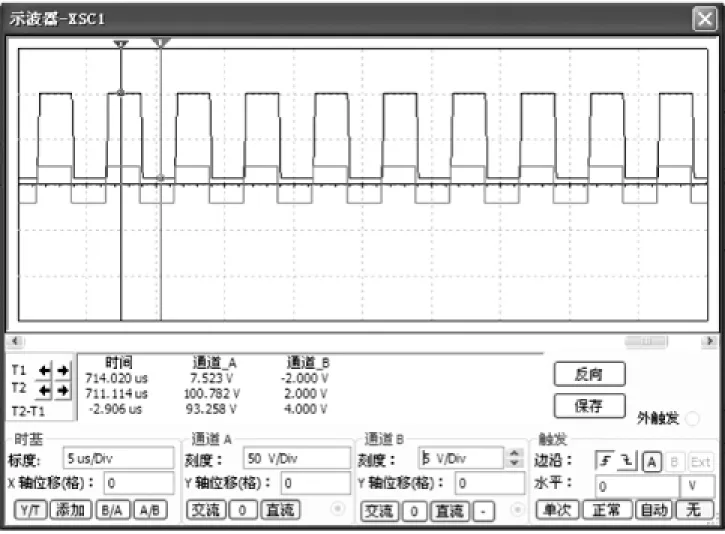
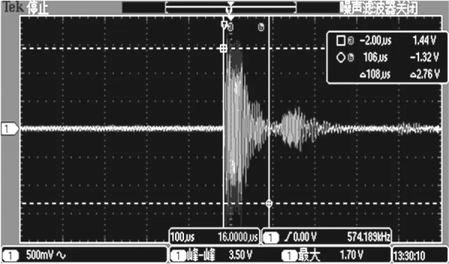
In order to verify the ability of the designed transmitting circuits,we simulate the transmitting amplifier circuit firstly using Multisim software. The simulation using the signal generator generates a square wave output of 2 V as the D/A converter output. The square wave is amplified to 100 V by PA85 amplifier. The simulation results are shown in Fig.7. Six channels phased array transmitting circuits of the system respectively connected with the six elements of the transducer array,transducer array is positioned under the water,set the distance between the array surface and the object as 20 cm. Measurement of echo signal received by the receiving transducer is as shown in Fig.8.

Fig.7 The simulation waves of amplifying circuit

Fig.8 Echo signal received by the receiving transducer
In Fig.8,we can see that the received ultrasonic echo signal is large enough to distinguish before the filter and amplification. The echo signals through filter and amplifier send to a computer for image processing algorithms,we will obtain images with high resolution.
4 Conclusion
In this paper we present a new type of underwater ultrasonic phased array transmitting system. FPGA control module and the transmitting amplifier circuits are designed,and ultrasonic signals phased transmitting with high voltage and high frequency achieved,and a low power supply voltage and high integration design reached at the same time. Experimental results show that the designed circuits can product 6 channels phased transmitting with time delay precision of 2.5 ns,
and the transmitting signals are strong,which provides a hardware foundation for the imaging experiments of underwater ultrasonic transducer arrays. The system uses modular design,it is easy to large-scale multi channels expansion,provide a new way for the underwater ultrasonic imaging and it has high application value.
[1] Tian Xiaodong,Liu Zhong. Modeling and Simulation of Underwater Detection System Based on Imaging Sonar[J]. Computer Simulation,2006,23(11):176-179.
[2] Paul A Meyer,J W Anderson. Ultrasonic Testing Using Phased Arrays[C]//Processing of 15th World Conference on NDT. Rome,Italy:2000:130-134.
[3] Kong Chao,We Gong,Shi Fangfang,et al. The Realization of High-Precision Phased Transmission and Parallel Processing of Phased echo in Phased Array Ultrasonic System[J]. Nondestructive Testing,2010,32(12):966-969.
[4] Shi Yiwei. Ultrasonic Detection[M]. Beijing:China Machine Press,2005:7-36.
[5] Kröning M. Improving the Inspect Ability of Stainless Steel and Dissimilar Metal Welded Joints Using Inverse Phase-Matching of Phased Array Time-Domain Signals[C]//17thWorld Conference on Nondestructive Testing. Shanghai,China:2008:308-316.
[6] Li Yan. Ultrasonic Phased Array Technology[J]. NDT,2008,32(2):23-31.
[7] Kuang Yinghui. Research on Modeling and Parameter Optimization of Ultrasonic Phased Array[J]. Chinese Journal of Sensors and Actuators,2010,23(12):1731-1735.
[8] Jiang Lei,Cai Ping,Yang Juan,et al. Research and Design of a New-Type Underwater Acoustic Transmitter[J]. Piezoelectrics and Acoustooptics,2007,29(6):676-679.
[9] Bao Xiaoyu,Shi Keren,Chen Yifang,et al. High-Precision Phased Ultrasonic Transmission in Phased Array Ultrasonic Systems[J]. J Tsinghua Univ(Sci and Tech),2004,44(2):153-156.
[10] Yang Bin,Wang Zhaoba,Chen Youxing. High-Precision Phased Ultrasonic Transmission in Phased Array Ultrasonic Systems Based on CPLD[J]. China Measurement Technology,2007,33(2):10-12.
Design of Ultrasonic Phased Array Transmitting System Based on FPGA
DUChunhui1,2*
(1.Taiyuan Institute of China Coal Technology and Engineering Group,Taiyuan 030006,China; 2.Shanxi Tiandi Coal Mining Machinery Co.,Ltd.,Taiyuan 030006,China)
In order to make underwater acoustic imaging system miniaturization,combine phased-array technology with underwater ultrasonic imaging technology originally,the ultrasonic phased array transmitting system based on FPGA is designed. The transmitting principle of phased focus is analyzed,and the six channels ultrasonic phased array transmitting system is achieved by using FPGA with rich I/O pins and internal logic resources. Then the signal conditioning circuit for excitation signal D/A conversion and amplification are designed to motivate the piezoelectric transducer effectively. The actual test results show that the system achieved ultrasonic signal phased array focus transmitting,phase delay precision is 2.5 ns. The system with high integration and stable transmitting signal,which provide a new way for the underwater ultrasonic imaging,it has high application value.
underwater ultrasonic imaging;phased array transmitting;FPGA;piezoelectric transducer

2016-03-14 修改日期:2016-05-16
C:7810
10.3969/j.issn.1005-9490.2017.02.012
TB553
A
1005-9490(2017)02-0321-05

