Stability Analysis of Cross-channel Excavation for Existing Anchor Removal Project in Subway Construction
Li Bin, Fang Hongyuan*, He Wei, Sun Bin
1 Introduction
With the development of urbanization in China, the urban population density increases rapidly. The traffic congestion, limited land resources have become the serious problems of urban development. The underground space development will be the inevitable solution to this problem. In recent years, the urban subway construction is rapidly developed in China. There are 37 cities open the subway and the total mileage is up to 3529 km.
Shield tunneling is the most widely used subway construction method now. However, the pile-anchor joint supporting system is mostly adopted in the design of urban high-rise building foundation in China, it is inevitable that shield machine will pass through the area of anchor cable existing during the subway shield construction. If the existed anchor cable can not be removed ahead, the shield cutter head may be stuck with it, and the excavation efficiency of shield machine will be affected obviously. Therefore, how to quickly, economically and efficiently remove the existing anchor cable in the subway shield process has become an urgent problem to be solved in underground development.There are three technologies mainly used to remove the existing anchor cable. (1)The cut and cover method, the advantage of this method is that the construction risk is small and the anchor cable can be removed completely, but this way is affected greatly by the existed underground pipelines; (2)Vertical cutting method, i.e. the underground anchor cable is cut off by full casing drill machine on the ground. The advantage of this method is that the excavation is not necessary and the influence on the surrounding buildings is relatively small. However, there are some shortcomings that the anchor cable can not be completely removed and the anchor cable after shearing still exists in the soil, which may cause the shield head stuck. (3)Subsurface excavation method, the advantage of this way is that it occupies less space during construction and can effectively avoid the influence on the surrounding soil and pipelines.
As shown in Fig.1, the shield tunnel line of Zhengzhou Metro Line 5 pass through the Yaxin square where the underground anchor cables exist. The design data shows that the anchor cable is made up of 4 steel wire, the diameter is 15.2mm and the buried depth is 5.5 m. The green belt and pedestrian walkway are on the ground of cross section of the anchor cable and the shield tunnel line, and there are many buried sewage pipelines,water supply pipelines, and natural gas pipelines underground. Therefore, subsurface excavation method is applied to cut the existed anchor cable in the shield tunnel line.
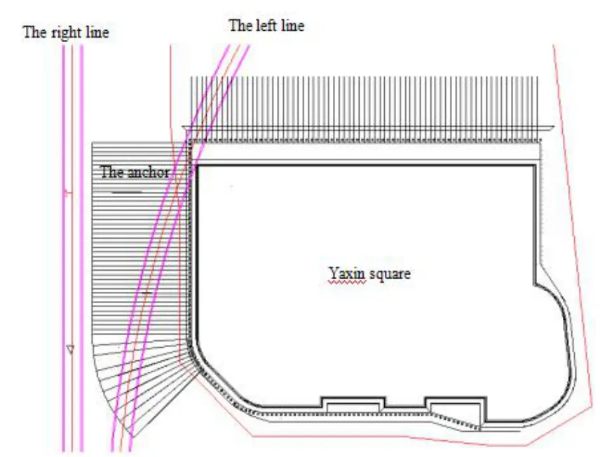
Figure 1: The plane position of anchor of the foundation
The subsurface excavation construction techniques mainly include: (1) Digging vertical shaft to the lower area where the anchor cable exist; (2) Digging the cross-channel along the shield axis line to the location of the anchor cable artificially;(3) Casing cutting the anchor cable by full-hydraulic all-casing drilling equipment;(4) Backfilling the cement mortar.
The stability of cross-channel excavation is very important in the subsurface excavation construction, the tunnel excavation size, lining thickness and lining order have great influence on the displacement response of the surrounding soil. Due to the complexity of the underground soil properties and the groundwater, the classical soil mechanics is impossible to analysis the cross-channel excavation. The finite element analysis is an effective way to solve this problem The two-dimensional plane strain model was used by[Clough G W, Shirasuna T, Finno R J. (1985)] to simulate the stress-strain of the formation caused by shield construction, and the horizontal and vertical displacement of the formation is analyzed; [Lee K M, Powe R K, Lo K Y. (1992)] calculated the displacement response of the metro excavation by means of finite element method, and the simulation results were consistent with the measured; The soil displacement and surface settlement caused by the construction of urban subway tunnel was analyzed by[SUN J, LIU H Z. (2002)]; A method to determine the excavation size of soft rock tunnels was developed by [LEE Y Z, SCHUBERT W. (2008); LIU F L, LIU Y L, HU B.(2013)]used the MIDAS/GTS software to built the model of the tunnel excavation of Wuhan subway, and surface subsidence caused by tunnel excavation was calculated; The actual construction process of subway tunnel under excavation unloading effect was simulated by [HONG G Y, et al. (2013)]; The stability of Karst tunnel surrounding soil and supporting is analyzed based on the finite element analysis software ANSYS by [ZHENG X J, WU M T. (2017)].
In this paper, ABAQUS finite element software is applied to analyze the stability of cross-channel excavation. The deformation of surrounding soil with different tunnel excavation size, lining thickness and lining order are simulated. Through analyzing the arch crown settlement, the intrados uplift and the lateral wall horizontal convergence of the cross-channel, the optimum construction scheme is selected.
2 Simulation model
2.1 Simulation parameters
The bench cut method is applied to cross-channel excavation and the support system contains initial liner of spray concrete, steel arch support, and anchor stock. The three-dimensional FEM model of cross-channel excavation is performed by using ABAQUS. The length, height and width of the FEM model is 4m, 30m and 30m,respectively, the buried depth of the cross-channel is 10m. The benching tunneling construction method is used in this model, and the soil layers of the model are set up according to the actual engineering survey results. The calculation model and the lining model are shown in Fig.2 and Fig.3. The eight-noded linear brick (C3D8R) is applied,and the structure-soil interface is modeled by using node-to-surface method. The modulus and poisson’ ratio of lining is 19GPa and 0.2, respectively, and the specific material parameters of each soil layer are shown in Tab. 1.
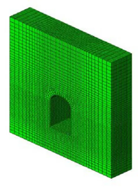
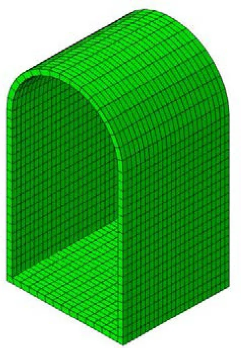
Figure 3: The lining model

Table 1: Material parameters
2.2 Step setting of each excavation
In order to evaluate the influence of stability on cross-channel excavation under different excavation size, lining thickness and lining order and choose an optimum excavation scheme, nine different excavation scheme are set as follows:
Excavation scheme 1: upper tunnel excavation (1m) - lower tunnel excavation (1m) -spray concrete lining (200mm) - steel arch supports - anchor
Excavation scheme 2: upper tunnel excavation (1m) - spray concrete lining (200mm) -steel arch supports - anchor - lower tunnel excavation (1m) - spray concrete lining(200mm) - steel arch supports - anchor
Excavation scheme 3: upper tunnel excavation (1m) - lower tunnel excavation (1m) -spray concrete lining (250mm) - steel arch supports - anchor
Excavation scheme 4: upper tunnel excavation (1m) - spray concrete lining (250mm) -steel arch supports - anchor - lower tunnel excavation (1m) - spray concrete lining(250mm) - steel arch supports - anchor
Excavation scheme 5: upper tunnel excavation (2m) - lower tunnel excavation (2m) -spray concrete lining (200mm) - steel arch supports - anchor
Excavation scheme 6: upper tunnel excavation (2m) - spray concrete lining (200mm) -steel arch supports - anchor - lower tunnel excavation (2m) - spray concrete lining(200mm) - steel arch supports - anchor
Excavation scheme 7: upper tunnel excavation (2m) - lower chamber excavation (2m) -spray concrete lining (250mm) - steel arch supports - anchor
Excavation scheme 8: upper tunnel excavation (2m) - spray concrete lining (250mm) -steel arch supports - anchor - lower tunnel excavation (2m) - lining (250mm) - steel arch supports - anchor
Excavation scheme 9: upper tunnel excavation (0.5m) - spray concrete lining (250mm) -steel arch supports - anchor - the lower tunnel excavation (0.5m) - spray concrete lining(250mm) - steel arch supports - anchor
3 Numerical results
3.1 The influence of excavation size on cross-channel
In order to study the influence of excavation size on the deformation of the surrounding soil, the time-spatial effects of scheme 1(excavation size is 1m), scheme 5(excavation size is 2m) and scheme 9(excavation size is 0.5m) are analyzed in this section.
Three paths on arch crown, arch bottom and side wall along the tunnel face forward direction are taken to study the arch crown settlement, intrados uplift and side wall horizontal convergence. The vertical and horizontal displacement cloud map of scheme 1,scheme 5 and scheme 9 are shown in Fig.4. The arch crown settlement, intrados uplift and side wall horizontal convergence contrast curves of scheme 1, scheme 5 and scheme 9 are shown in Fig.5.
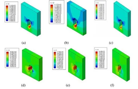
Figure 4: (a) The vertical displacement of scheme 1; (b) The vertical displacement of scheme 5; (c) The vertical displacement of scheme 9; (d) The horizontal displacement of scheme 1; (e) The horizontal displacement of scheme 5; (f) The horizontal displacement of scheme 9.

Figure 5: (a) Contrast curve of arch crown settlement; (b) Contrast curve of intrados uplift; (c) Contrast curve of side wall horizontal convergence
As observed in Fig.4 and Fig.5, the arch crown settlement, intrados uplift and side wall horizontal convergence is positively related to the excavation size. With the tunnel face advancing, intrados uplift and side wall horizontal convergence showed zigzag phenomenon; the horizontal convergence of scheme 1 and scheme 5 increasing slowly along the tunnel face forward direction, however, which that of scheme 9 is gradually decreasing.
The influence of the excavation size on the arch crown settlement, intrados uplift and side wall horizontal convergence spatial effect indicated that the reasonable size of the excavation can effectively control the deformation of the surrounding soil.
In order to investigate the time effect on the arch crown settlement of the cross-channel under different excavation sizes, three monitoring points are taken at the front, middle and tail of the crown, and the vertical displacement time history curves of each monitoring point are performed in Fig.6.

Figure 6: (a) Displacement time history curve of the front monitoring point; (b)Displacement time history curve of the middle monitoring point; (c) Displacement time history curve of the tail monitoring point
As shown in Fig.6, the maximum settlement of the front, middle and tail monitoring points of scheme 1 is 2.21mm, 2.22mm and 2.19mm, scheme 5 is 7.78mm, 6.75mm and 8.2mm, and scheme 9 is 2.5mm, 2.7mm and 2.4mm, respectively; The vertical displacement of the monitoring points are on the increase during the whole process, the increase amplitude of scheme 9 is the smallest, and the scheme 5 is the largest, it demonstrates that the excavation size and increase rate of the arch crown settlement is positively correlated.
3.2 The influence of lining thickness on cross-channel
Lining is an important link of tunnel construction, and is a key factor to control the deformation of surrounding soil. Scheme 5(lining thickness is 200mm) and scheme 7(lining thickness is 250mm) are selected in this part to investigate the time-spatial effect of lining thickness on cross-channel excavation.
The paths (mentioned above) are used to analyze the arch crown settlement, intrados uplift and side wall horizontal convergence during the excavation. The vertical and horizontal displacement of scheme 5 and scheme 7 are shown in Fig.7. The contrast curve of scheme 5 and scheme 7 are shown in Fig.8.
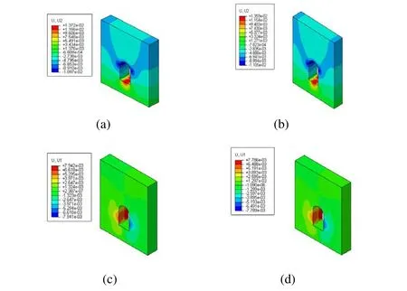
Figure 7: (a) The vertical displacement of scheme 5;(b) The vertical displacement of scheme 7;(c) The horizontal displacement of scheme 5;(d) The horizontal displacement of scheme 7

Figure 8: (a) Contrast curve of arch crown settlement; (b) Contrast curve of intrados uplift; (c) Contrast curve of side wall horizontal convergence
As shown in Fig.7 and Fig.8, the arch crown settlement value of scheme 5 is about 0.5~1mm higher than that of the scheme 7, the arch crown settlement decreased first and then increased along the tunnel face direction; the intrados uplift value of scheme 5 is about 0.5~1mm larger than that of the scheme 7, the intrados uplift changes relatively stable at the first excavation process, and a high degree of discontinuity occurs at the interface of the two excavation, then slowly increased at the second excavation process;the side wall horizontal convergence value of scheme 5 is approximately 0.5~0.8mm bigger than the scheme 7, the trend of which is increased in the whole process besides the interface of the two excavation, but the increase amplitude of the second excavation is larger than the first excavation.
The vertical displacement time history curves of each monitoring point (mentioned above)are shown in Fig.9.

Figure 9: (a) Displacement time history curve of the front monitoring point; (b)Displacement time history curve of the middle monitoring point; (c) Displacement time history curve of the tail monitoring point
It can be seen from Fig.9 that vertical displacement time history curves of scheme 5 and scheme 7 are basically the same, demonstrating that the lining thickness has little influence on time effect of the arch crown settlement.
3.3 The influence of lining order on cross-channel excavation
In the tunnel engineering, a reasonable application of lining can give full play to the carrying capacity of the surrounding soil, thereby can reduce the requirement of the lining.The scheme 5(the upper and lower chambers are lined together) and scheme 6(the upper and lower chambers are lined separately) are selected to observe the deformation of the surrounding soil in this section.
The vertical displacements of the paths (mentioned above) are analyzed. The vertical displacement and horizontal displacement of scheme 5 and scheme 6 are shown in Fig.10.The arch crown settlement, intrados uplift and side wall horizontal convergence contrast curve of scheme 5 and scheme 6 are shown in Fig.11.
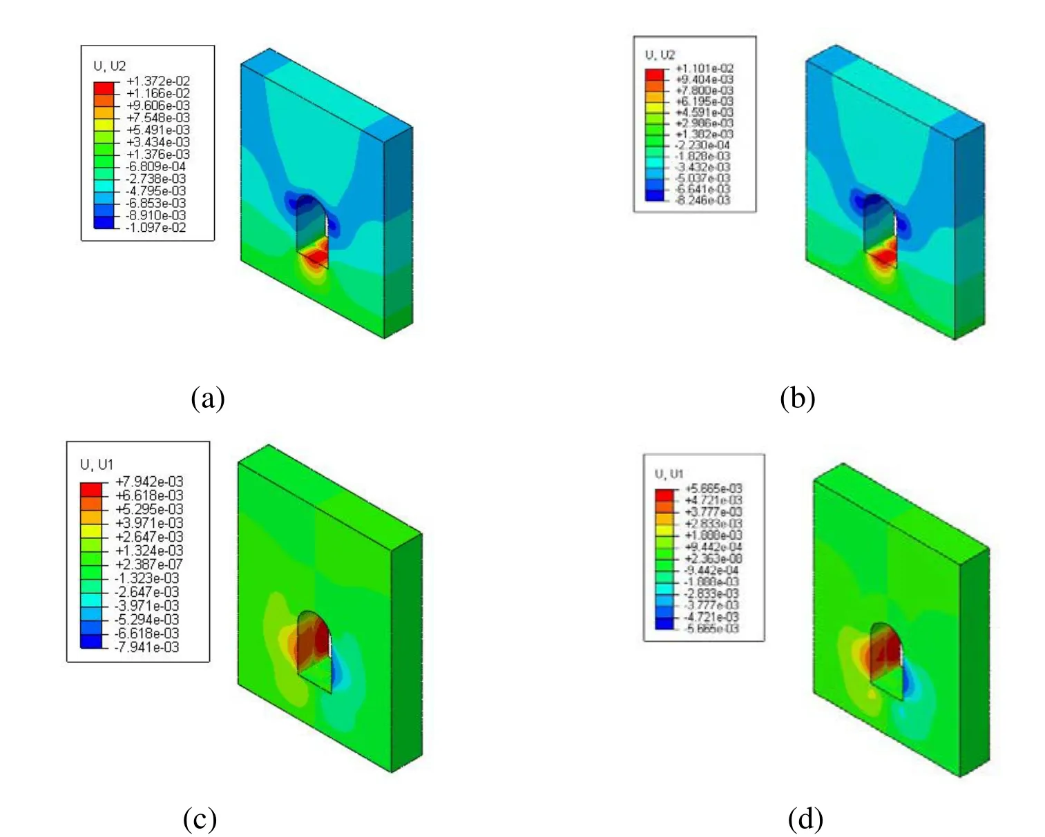
Figure 10: (a) The vertical displacement of scheme 5;(b) The vertical displacement of scheme 6;(c) The horizontal displacement of scheme 5;(d) The horizontal displacement of scheme 7
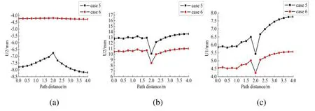
Figure 11: (a) Contrast curve of arch crown settlement; (b) Contrast curve of intrados uplift; (c) Contrast curve ofside wall horizontal convergence
It can be seen from Fig.10 and Fig.11 that the maximum value of arch crown settlement,intrados uplift and the lateral wall horizontal convergence of scheme 5 are about 4.0mm,2.5mm and 2.3mm larger than scheme 6, respectively, which shows that the lining order has a greater influence on the arch crown settlement, the intrados uplift and the lateral wall horizontal convergence.
Intent to observe the time effect of the arch crown settlement of the cross-channel with different lining order, the vertical displacement time history curves of each monitoring point are shown in Fig.12.
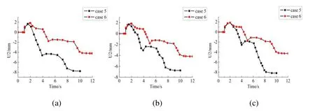
Figure 12: (a) Displacement time history curve of the front monitoring point; (b)Displacement time history curve of the middle monitoring point; (c) Displacement time history curve of the tail monitoring point
It can be seen from Fig.12 that the vertical displacement of the monitoring points of scheme 5 and scheme 6 are increased rapidly, the vertical displacement of the scheme 5 is larger than the scheme 6 during the whole process, it indicated that lining order has great influence on the time effect of the surrounding soil deformation.
4 Scheme comparison
In order to choose an optimal excavation scheme from all the excavation schemes, the time-spatial effects on the surrounding soil deformation of the cross-channel under different excavation schemes are compared.
The arch crown settlement, intrados uplift and side wall horizontal convergence contrast curve of all scheme are shown in Fig13.

Figure 13: (a) Contrast curve of arch crown settlement; (b) Contrast curve of intrados uplift; (c) Contrast curve of side wall horizontal convergence
As shown in Fig.13 that the minimum arch crown settlement, intrados uplift and side wall horizontal convergence is the scheme 9, and the biggest is scheme 5. In view of the spatial effect on the deformation of the cross-channel surrounding soil, the scheme 9 is the best and the scheme 5 is the worst.
The vertical displacement time history curves of each monitoring point (mentioned above)are shown in Fig.14.
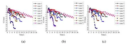
Figure 14: (a) Displacement time history curve of the front monitoring point; (b)Displacement time history curve of the middle monitoring point; (c) Displacement time history curve of the tail monitoring point
It can be seen from Fig.14 that the minimum settlement of the front, middle and tail monitoring points is scheme 9, and the largest is scheme 5 and scheme 7. Simultaneously,the vertical displacement increases trend of each monitoring point of scheme 5 and 7 is largest in the whole process, while the scheme 9 is minimum. Considering the value of the surrounding soil deformation and the deformation increases rate, the scheme 9 is the best choice and the scheme 7 is the worst
Through comparing and analyzing the time-spatial effect on the surrounding soil under the nine excavation schemes, the scheme 9 is the optimum scheme, and it will be adopted in the actual project.
5 Conclusions
In this paper, a three-dimensional FEM is performed by using ABAQUA software to study stability of cross-channel excavation, the time-spatial effects of surrounding soil deformation under different excavation sizes, lining thicknesses and lining orders are investigated. The following conclusions are obtained:
(1) The excavation size is one of the main factors controlling the deformation of the surrounding soil, and the influence on arch crown settlement is the most obvious;
(2) The influence of lining thickness on spatial effect of surrounding soil deformation is obvious when the excavation size is large, however, the influence on time effect is weak;
(3) The influence of the lining order on the deformation of the surrounding soil is obvious in time-spatial effects, in particular, the larger the excavation size is, the advantage of the lining order is more obvious, and the influence on the arch crown settlement is much greater than the intrados uplift and side wall horizontal convergence;
(4) The time-spatial effects comparison of nine excavation schemes are developed to determine the optimum excavation scheme applied to the actual project.
Acknowledgement This research was supported by The National Natural Science Foundation of China (No.41404096, 51678536, 51509224), The Scientific and Technological Research Program of Henan Province(No.152102310066) and Outstanding Young Talent Research Fund of Zhengzhou University(1621323001) for which the authors are grateful.
Clough G W, Shirasuna T, Finno R J. (1985) Finite element analysis of advanced shield tunneling in soils[J].International conference on numerical methods in geomechanics: 1167-1174.
Lee K M, Powe R K, Lo K Y. (1992) Subsidence owing to tunneling in estimating the gap parameter[J]. Canadian Geotechnical Journal, 29(6): 929-940.
SUN J, LIU H Z. (2002) 3-D Numerical Simulation of Ground Surface Settlement under Overlapped Shield. Tunneling[C]. Journal of Tongji University,, 30(4):3
L7E9E-3 8Y5. Z, SCHUBERT W. (2008) Determination of the round length for tunnel excavation in weak rock[J].Tunneling and underground space technology,23(3) : 221-231.
LIU F L, LIU Y L, HU B.(2013) Numerical simulation of ground subsidence due to tunnel excavation for wuhan subway[J]. Journal of Engineering Geology, 21(1): 85-91.
HONG G Y, et al. (2013) Numerical analysis of subway tunnel construction process based on excavation unloading effect[J]. Chinese Journal of Rock Mechanics and Engineering, 32(Supp 1): 2916-2924.
ZHENG X J, WU M T. (2017) Numerical simulation analysis on stability of karst tunnel surrounding soil and supports[J]. Highway Engineering, 42(2): 170-174
 Computer Modeling In Engineering&Sciences2017年1期
- Computer Modeling In Engineering&Sciences的其它文章
- Acoustic Scattering Performance for Sources in Arbitrary Motion
- Inverse Analysis of Origin-Destination matrix for Microscopic Traffic Simulator
- Optimization of Nonlinear Vibration Characteristics for Seismic Isolation Rubber
- A Study on the Far Wake of Elliptic Cylinders
- Reliability Analysis for Complex Systems based on Dynamic Evidential Network Considering Epistemic Uncertainty
- Modeling of Canonical Switching Cell Converter Using Genetic Algorithm
