A modified airfoil-based piezoaeroelastic energy harvester with double plunge degrees of freedom
Yining Wu,Dochun Li,Jinwu Xing,∗,Andre D Ronch
aSchool of Aeronautic Science and Engineering,Beihang University,Beijing 100191,China
bEngineering and the Environment,University ofSouthampton,Southampton SO171BJ,UK
Letter
A modified airfoil-based piezoaeroelastic energy harvester with double plunge degrees of freedom
Yining Wua,Daochun Lia,Jinwu Xianga,∗,Andrea Da Ronchb
aSchool of Aeronautic Science and Engineering,Beihang University,Beijing 100191,China
bEngineering and the Environment,University ofSouthampton,Southampton SO171BJ,UK
H I G H L I G H T S
.A double-plunge airfoil-based piezoaeroelastic energy harvester is proposed.
.The dynamic modelof the proposed harvester is presented.
.The proposed harvester generates higher power outputthan conventionaldesigns.
.The proposed harvester has lower cut-in speed than conventionaldesigns.
A R T I C L E I N F O
Article history:
Received 7 June 2016
Received in revised form
3 July 2016
Accepted 7 August 2016
Available online 24 August 2016
Energy harvesting Aeroelastic Airfoil Piezoelectric
In this letter,a piezoaeroelastic energy harvester based on an airfoil with double plunge degrees of freedom is proposed to additionally take advantage of the vibrationalenergy ofthe airfoilpitch motion. An analyticalmodelofthe proposed energy harvesting system is built and compared with an equivalent model using the well-explored pitch-plunge configuration.The dynamic response and average power output of the harvester are numerically studied as the flow velocity exceeds the cut-in speed(flutter speed).It is found that the harvester with double-plunge configuration generates 4%-10%more power with varying flow velocities while reducing 6%of the cut-in speed than its counterpart.
©2016 The Author(s).Published by Elsevier Ltd on behalf of The Chinese Society of Theoreticaland Applied Mechanics.This is an open access article under the CC BY-NC-ND license(http:// creativecommons.org/licenses/by-nc-nd/4.0/).
The objective of energy harvesting(EH)is to convert ambient energy such as solar,tidal,and wind energy into available electric energy.Recently,EH based on aeroelastic vibrations has received growing attention since it potentially outperforms the conventionalturbines in terms of smallscale wind EH[1].The harvested energy can be used for low-power electronic systems such as wireless sensor networks to reduce cabling and maintenance costs[2].
Taking advantage of aeroelastic phenomena,several harvesters have been designed,manufactured,and tested based on flutter of cantilevered plates[3,4],galloping oscillations of bluff bodies [5,6],wake galloping phenomenon[7,8],and vortex-induced vibrations[9,10].Airfoil-based energy harvesters,exploiting aeroelastic vibrations,consist of a rigid airfoilwith supporting devices that allow the pitch-plunge vibrations of the airfoil with transducers coupled to the plunge degree of freedom(DOF)[11,12]. Towards airfoil-based harvesters,a large body of work has been done including analytical modeling and experimental activities[13,14],investigating the effects of structural nonlinearities[15-18]and system parameters[19-23]to improve EH performance,and analyzing EHunder the combined base and wind excitations[24,25].Cambered airfoils[26]and 3-DOF airfoils with control surfaces[27,28]were also considered to enhance design flexibility.
Previous studies on piezoaeroelastic EH of airfoil-based harvesters used a pitch-plunge configuration with piezoelectric transducers coupled to the plunge DOF.The airfoils were generally held by torsional springs and rotating shafts connected to cantilevered piezoelectric beams.The coupling between the transducers and the pitch DOF was not considered in the previous studies because (1)it is difficult to attach the piezoelectric transducers to the torsionalsprings,and(2)it is relatively hard to convertthe airfoilpitch motion into the deformation of the piezoelectric materials compared with the use of the piezoelectric beams.From an EH point of view,however,the vibrational energy in the pitch DOF was not converted into electric energy and wasted.The objective of thisletter is to enhance the performance of airfoil-based harvesters by additionally taking advantage of the vibrational energy of the airfoilpitch motion.
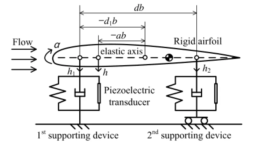
Fig.1.Schematic of the airfoil-based harvester with double plunge DOFs.
As it is very difficult to couple the piezoelectric transducers to the pitch DOF,an airfoilwith double plunge supporting devices is used.Shown in Fig.1,a second plunge DOF is introduced instead of the pitch DOF.The mechanical energy of each plunge DOF is converted into electric energy via the corresponding transducer and then consumed by a load resistance in the respective circuit.
Shown in Fig.1,the displacements of two plunge supporting devices are denoted by h1and h2,positive downward.The terms d1and a denote,respectively,the dimensionless offset ofthe first supporting device and the elastic axis from the airfoil mid-chord. The term d is the dimensionless offset of the second supporting device measured from the first one.The location of the elastic axis is determined by a=d1+k2d/(k1+k2),where k1and k2are the linear stiffness coefficients of the two plunge DOFs, respectively,including the contributions from both the plunge springs and transducers.The dynamic equations of the proposed double-plunge airfoil-based piezoaeroelastic harvester are derived as
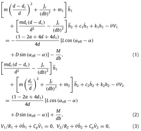
where dc=a−d1+xα,and xαis the dimensionless offset of the gravity center axis measured from the elastic axis;m,m1,and m2are,respectively,the mass of the airfoil,the first,and the second supporting device;Jcis the moment of inertia of the airfoil about the gravity center axis;b is the airfoil semi-chord;c1and c2are the damping coefficients of the two plunge DOFs,respectively;V1and V2are the voltage outputs ofthe two transducers,respectively; θis the electromechanical coupling factor;Cpis the equivalent capacitance of the transducers;R1and R2are the load resistances in respective circuits.Note that the structural nonlinearities are not taken into account in this work.αeffis the effective angle of attack,andαeff= α+ ˙h/U− (0.5+a)b˙α/U,where h is the plunge displacement of the elastic axis,positive downward,and αis the pitch displacement,positive nose up;L= ρU2bCl,D= ρU2bCd,and M=2ρU2b2Cmare the aerodynamic lift(normalto the direction of the resultant flow velocity,positive upward),drag (along the resultant flow velocity,positive leeward),and moment (positive nose up)acting at the airfoil one-quarter-chord axis, respectively,whereρis the air density and U is flow velocity.The aerodynamic coefficients are calculated using the Office National d'Etudes et de Recherches Aerospatiales(ONERA)dynamic stall model[29]to consider the effects of flow separation due to large airfoilamplitudes.The aerodynamic model used in this work is
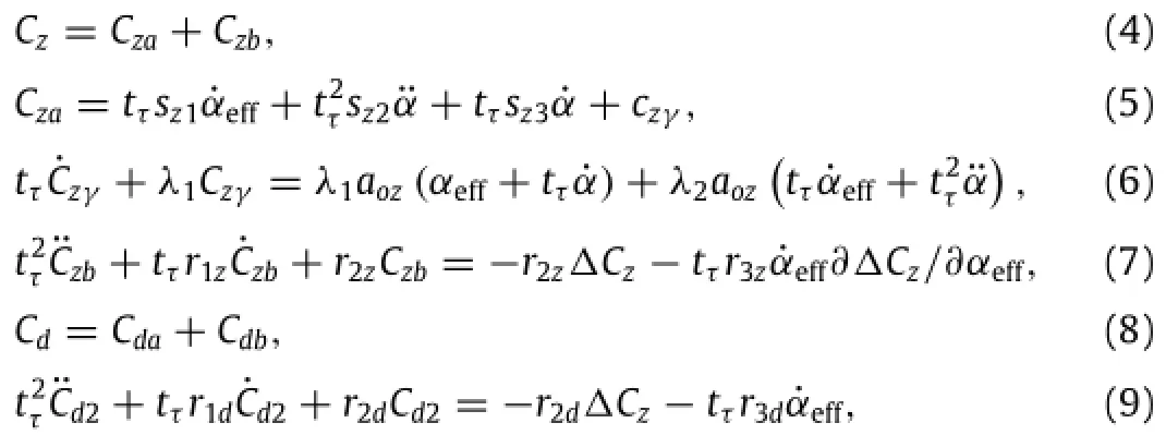
where subscript z can be l or m to indicate,respectively,lift or moment coefficient;tτ=b/U.Subscripts a and b refer to the linear and nonlinear parts of the aerodynamics,respectively;the coefficients are sl1= π,sl2= π/2,sl3=0,sm1= −π/4,sm2=−3π/16,sm3=−π/4,λ1=0.15,λ2=0.55,aol=5.9,aom=0, cd1=0.014,r1d=0.32;the terms with respect to the nonlinear aerodynamics in Eqs.(7)and(9)are given in the Appendix.The relationship between h1,h2and h,αcan be expressed via a transfer matrix

To verify the advantage of EH based on the double-plunge airfoil,an equivalent pitch-plunge airfoil-based EH model is built. Shown in Fig.2,the plunge DOF ofthe equivalent modelis coupled with two transducers in parallel to ensure the use of the same amount of piezoelectric material.For this pitch-plunge airfoilbased harvester,the dynamics are
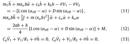
where khand kαare,respectively,the stiffness coefficients of the plunge and pitch DOFs;chand cαare the damping coefficients of these two DOFs,respectively;mTis the total mass of the airfoil together with its supporting devices;J is the moment of inertia of the pitch-plunge airfoil about the gravity center axis.The relationships between the mass,stiffness,and damping coefficients of the two harvesters are derived as

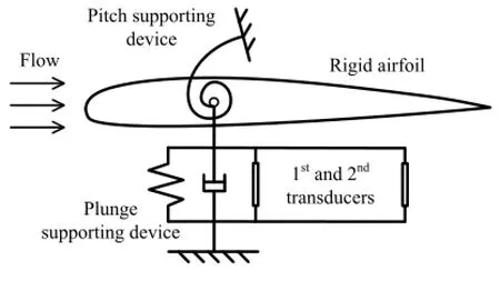
Fig.2.Schematic ofan equivalentpitch-plunge airfoil-based harvester.
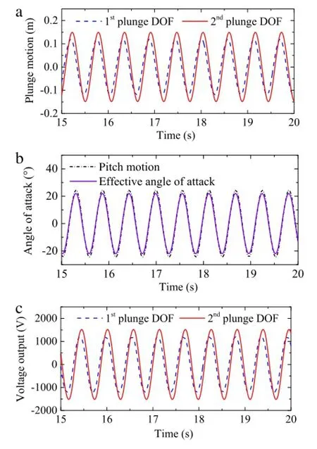
Fig.3.Time histories of(a)the plunge motion,(b)the pitch motion,and(c)the voltage output of the proposed harvester as the flow velocity is 30 m.s−1.
For EH based on two transducers via respective circuits,the total harvested energy is evaluated by the average power output

where t1to t2is a period of time in which the transient response has been dissipated.
The dynamic equations are solved numerically using the Runge-Kutta method.For all results presented,the initial conditions are˙h1=0.01 and zeroes for the rest of the state variables. The value of the system parameters are:m=2.049 kg;m1= m2=10.338 kg;b=0.135 m;xα=0.331;d1=−1;d=1;Jc= 0.0517 kg.m2;c1=c2=27.43 kg.s−1;k1=k2=1000 N.m−1; θ=1.55 X10⁻³N.V−1;Cp=1.2 X10⁻⁷F;R1=R2=1 X 10⁶Ω. The air density is 1.225 kg.m−3and the viscosity coefficient is 1.78 X10⁻⁵Pa.s.To calculate the average power output,the time period t1to t2in Eq.(17)corresponds to the last 10 s of the total simulation time(30 s)where the transient responses are observed to be completely dissipated.The cut-in speed(flutter speed)ofthe harvester is determined as 28.4 m.s−1.The time history results as the flow velocity is 30 m.s−1are shown in Fig.3.Itis shown that the plunge amplitude and voltage outputofthe second plunge DOF are larger than that of the first plunge DOF.Besides,the effective angle ofattack can be large enough to cause flow separation,e.g.,the amplitude is 22°shown in Fig.3(b).This demonstrates the necessity ofusing the dynamic stallmodelto calculate the aerodynamics in this work.
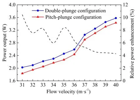
Fig.4.Average power outputs of the harvesters with double-plunge and pitchplunge configurations with the flow velocity(solid lines),and the relative enhancementofthe power output(dash line).
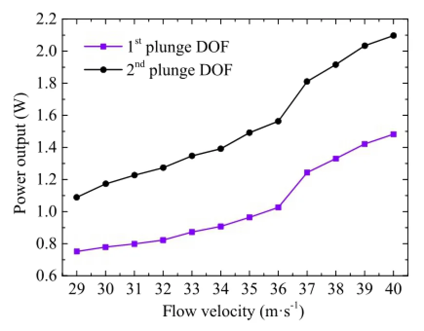
Fig.5.Average power outputs of the first and second plunge DOFs with the flow velocity.
The double-plunge airfoil-based energy harvester is numerically compared with its pitch-plunge counterpart.The cut-in speed of the latter is firstly obtained as 30.2 m.s−1,which is larger than that of the former.This result shows that the use of the doubleplunge configuration improves the EH performance with a relative reduction 6%of the cut-in speed.The average power outputs of these two harvesters with the flow velocity are compared in Fig.4. Obviously,the power output using double-plunge configuration is larger than thatusing the pitch-plunge configuration.The relative enhancement of the power output is shown in Fig.4 by a dotted line.It can be seen that the enhancement in percentage varies with the flow velocity and fluctuates between 4%and 10%.Besides,the relationship between the power outputs of the two harvesters and the flow velocity is approximately piecewise linear.Specifically, the slopes of the two curves increase at 36 m.s−1and then descend as the flow velocity is beyond 37 m.s−1.
The comparison of the average power outputs of two plunge DOFs with the flow velocity is shown in Fig.5.In this work,the first plunge supporting device is at the leading edge of the airfoil while the second one is at the mid-chord axis.Also,the parameters of the two plunge supporting devices are set identically.It can be seen that the power output from the second plunge DOF islarger than that from the first plunge DOF.Specifically,the former is approximately 50%larger than the latter with varying flow velocity.
In summary,this letter proposes a piezoaeroelastic energy harvester based on an airfoil with double plunge DOFs.The dynamic equations of this harvester and an equivalent well-explored pitchplunge airfoil-based harvester are presented.It is numerically demonstrated that the proposed harvester outperforms its counterpart using the pitch-plunge configuration in terms of the average power output and the cut-in speed.Specifically,it is found that the former generates 4%-10%more power with varying flow velocities while reducing 6%of the cut-in speed than the latter.It is also shown thatthe second downstream plunge supporting device of the proposed harvester has larger plunge amplitude and hence yields 50%more power output compared with the first upstream one.
Acknowledgments
This work was supported by the National Natural Science Foundation of China(11402014,11572023)and the Royal Academy of Engineering for the project''Fast Nonlinear Aeroelastic Search for Loads Assessment''(NCRP/1415/51).
Appendix
The terms with respect to the nonlinear aerodynamics in Eqs.(7)and(9)are:

if the Reynolds number is larger than 3.4 X 10⁵,and

ifthe Reynolds number is smaller than 3.4 X 10⁵.Besides,

whereα1=0.1396 andα2=0.3142.In addition,

[1]A.Abdelkefi,Aeroelastic energy harvesting:a review,Internat.J.Engrg.Sci. 100(2016)112-135.
[2]A.Truitt,S.N.Mahmoodi,A review on active wind energy harvesting designs, Int.J.Precis.Eng.Man.14(2013)1667-1675.
[3]M.Piñeirua,O.Doaré,S.Michelin,Influence and optimization ofthe electrodes position in a piezoelectric energy harvesting flag,J.Sound Vib.346(2015) 200-215.
[4]J.A.Dunnmon,S.C.Stanton,B.P.Mann,etal.,Power extraction from aeroelastic limit cycle oscillations,J.Fluid Struct.27(2011)1182-1198.
[5]A.Bibo,M.F.Daqaq,On the optimalperformance and universaldesign curves ofgalloping energy harvesters,Appl.Phys.Lett.104(2014)23901.
[6]Y.Yang,L.Zhao,L.Tang,Comparative study of tip cross-sections for efficient galloping energy harvesting,Appl.Phys.Lett.102(2013)64105.
[7]A.Abdelkefi,J.M.Scanlon,E.Mcdowell,et al.,Performance enhancement of piezoelectric energy harvesters from wake galloping,Appl.Phys.Lett.103 (2013)33903.
[8]H.Jung,L.Seung-Woo,The experimentalvalidation ofa newenergy harvesting system based on the wake galloping phenomenon,Smart Mater.Struct.20 (2011)55022.
[9]L.Ding,L.Zhang,M.M.Bernitsas,etal.,Numericalsimulation and experimental validation for energy harvesting of single-cylinder VIVACE converter with passive turbulence control,Renew.Energy 85(2016)1246-1259.
[10]J.Xu-Xu,A.Barrero-Gil,A.Velazquez,A theoreticalstudy of the coupling between a vortex-induced vibration cylindrical resonator and an electromagnetic energy harvester,Smart Mater.Struct.24(2015)115009.
[11]J.A.C.Dias,C.De Marqui Jr.,A.Erturk,Hybrid piezoelectric-inductive flow energy harvesting and dimensionless electroaeroelastic analysis for scaling, Appl.Phys.Lett.102(2013)44101.
[12]C.De Marqui Jr.,A.Erturk,Electroaeroelastic analysis of airfoil-based wind energy harvesting using piezoelectric transduction and electromagnetic induction,J.Intell.Mater.Syst.Struct.24(2013)846-854.
[13]M.Bryant,E.Garcia,Modeling and testing ofa novelaeroelastic flutter energy harvester,J.Vib.Acoust.133(2011)11010.
[14]A.Erturk,W.G.R.Vieira,C.De Marqui Jr.,et al.,On the energy harvesting potentialofpiezoaeroelastic systems,Appl.Phys.Lett.96(2010)184103.
[15]V.C.Sousa,M.de M Anicézio,C.De Marqui Jr.,et al.,Enhanced aeroelastic energy harvesting by exploiting combined nonlinearities:theory and experiment,Smart Mater.Struct.20(2011)94007.
[16]J.Bae,D.J.Inman,Aeroelastic characteristics of linear and nonlinear piezoaeroelastic energy harvester,J.Intell.Mater.Syst.Struct.4(2014)401-416.
[17]A.Abdelkefi,M.R.Hajj,Performance enhancement ofwing-based piezoaeroelastic energy harvesting through freeplay nonlinearity,Theor.Appl.Mech.Lett. 3(2013)41001.
[18]V.C.Sousa,C.De Marqui Jr.,Airfoil-based piezoelectric energy harvesting by exploiting the pseudoelastic hysteresis ofshape memory alloy springs,Smart Mater.Struct.24(2015)125014.
[19]M.Bryant,E.Wolff,E.Garcia,Aeroelastic flutter energy harvester design:the sensitivity ofthe driving instability to system parameters,Smart Mater.Struct. 20(2011)125017.
[20]A.Abdelkefi,A.H.Nayfeh,M.R.Hajj,Enhancement of power harvesting from piezoaeroelastic systems,Nonlinear Dynam.68(2012)531-541.
[21]A.Abdelkefi,A.H.Nayfeh,M.R.Hajj,Modeling and analysis ofpiezoaeroelastic energy harvesters,Nonlinear Dynam.67(2012)925-939.
[22]A.Abdelkefi,M.Ghommem,A.O.Nuhait,et al.,Nonlinear analysis and enhancement of wing-based piezoaeroelastic energy harvesters,J.Sound Vib. 333(2014)166-177.
[23]A.Abdelkefi,A.H.Nayfeh,M.R.Hajj,Design of piezoaeroelastic energy harvesters,Nonlinear Dynam.68(2012)519-530.
[24]A.Bibo,M.F.Daqaq,Investigation of concurrent energy harvesting from ambientvibrations and wind using a single piezoelectric generator,Appl.Phys. Lett.102(2013)243904.
[25]A.Bibo,M.F.Daqaq,Energy harvesting under combined aerodynamic and base excitations,J.Sound Vib.332(2013)5086-5102.
[26]A.Abdelkefi,A.O.Nuhait,Modeling and performance analysis of cambered wing-based piezoaeroelastic energy harvesters,Smart Mater.Struct.22(2013) 95029.
[27]J.A.C.Dias,C.De Marqui Jr.,A.Erturk,Three-degree-of-freedom hybrid piezoelectric-inductive aeroelastic energy harvester exploiting a control surface,AIAA J.53(2014)394-404.
[28]J.Bae,D.J.Inman,A preliminary study on piezo-aeroelastic energy harvesting using a nonlinear trailing-edge flap,Int.J.Aeronaut.Space Sci.16(2015) 407-417.
[29]P.Dunn,D.John,Nonlinear stallflutter and divergence analysis ofcantilevered graphite/epoxy wings,AIAA J.30(1992)153-162.
∗Corresponding author.
E-mail address:xiangjw@buaa.edu.cn(J.Xiang).
http://dx.doi.org/10.1016/j.taml.2016.08.009
2095-0349/©2016 The Author(s).Published by Elsevier Ltd on behalfof The Chinese Society of Theoreticaland Applied Mechanics.This is an open access article under the CC BY-NC-ND license(http://creativecommons.org/licenses/by-nc-nd/4.0/).
 Theoretical & Applied Mechanics Letters2016年5期
- Theoretical & Applied Mechanics Letters的其它文章
- Two-dimensionalmodeling of the self-limiting oxidation in silicon and tungsten nanowires
- Subset-based localvs.finite element-based globaldigitalimage correlation:A comparison study
- Magnetic induction strength on surface of a ferro-medium circular cylinder
- Numericalinvestigation of unsteady mixing mechanism in plate film cooling
- High temperature effects in moving shock reflection with protruding Mach stem
- The Richtmyer-Meshkov instability of a'V'shaped air/helium interface subjected to a weak shock
