
Multi-body dynamic simulation research on the influence of piston engine crankshaft thrust bearings abrasion①
2016-12-22 05:46:08YaoZiyun么子云JiangZhinongLiXinJiaYangZhangJinjie
High Technology Letters 2016年4期
Yao Ziyun (么子云), Jiang Zhinong, Li Xin, Jia Yang, Zhang Jinjie②
(*Diagnosis and Self-Recovery Engineering Research Center, Beijing University of Chemical Technology, Beijing 100029, P.R.China)(**Safety Detection and Intelligent System R&D of Beijing Rail Transit Engineering Research Center,Beijing Rail and Transit Design & Research Institute CO., LTD, Beijing 100089, P.R.China)
Multi-body dynamic simulation research on the influence of piston engine crankshaft thrust bearings abrasion①
Yao Ziyun (么子云)*, Jiang Zhinong*, Li Xin**, Jia Yang*, Zhang Jinjie②*
(*Diagnosis and Self-Recovery Engineering Research Center, Beijing University of Chemical Technology, Beijing 100029, P.R.China)(**Safety Detection and Intelligent System R&D of Beijing Rail Transit Engineering Research Center,Beijing Rail and Transit Design & Research Institute CO., LTD, Beijing 100089, P.R.China)
Fault diagnosis studying on piston engine, crankshaft and gearbox is focused in this paper. The thrust bearing abrasion caused by axial movement of the crankshaft will affect the force of timing gears and oil pump gears, which will result in the fracture of gears, abnormal ignition, connecting rod cracking and collision of cylinder. Simulation based on CREO software is done to build three-dimensional models of crankshaft and gears of a WP10 diesel engine. The models are imported into ADAMS to complete multi-body dynamics simulations. The force analysis of gears in different kinds of axial movements is finished and variations rules of gear dynamic load is obtained. The presented results show that the crankshaft axial movement can cause overload and vibration on gears. Combined with the realistic case data, the fault feature through simulation research is validated and early warming parameters of gear fault are proposed.
crankshaft, piston engine, axial movement, gear, multi-body simulation
0 Introduction
The piston engines, represented by diesel engine, gasoline engine and gas engine, are widely applied in industries such as ships, vehicles, petrochemical and engineering machinery. Taking ship building industry as an example, driving diesel engines and generator diesel engines take almost 5%~ 8% and 1%~ 3% of total construction costs. The piston engine works based on crankshaft, connecting rods and piston, and the forces acting on the crankshaft of the engine are complex because of the burst pressure of the cylinder.
Considering the diesel engine as the research focus, to date studies are tended to concentrate on optimal design of the diesel engine to improve performance and operating life. Some researchers have focused on the parts structure, seeking optimization of design of various parts such as crankshaft, camshaft and cooling system[1,2]; other academics have studied the dynamic performance focusing on: vibration, noise and fluidity of operation[3,4]; some pay attention to parts friction and want to improve the friction performance[5,6]; some academics want to improve the fuel economy and reduce diesel engine exhaust pollution and use the computational fluid dynamics simulation technology to optimize the performance of working processes such as combustion, fluid flow and energy transfer[7-10].
Diesel engine fault monitoring systems can complete data collection, analysis, processing of vibration signals, thermodynamic parameters and lubricating oil characteristics signals. Faults can be detected through signal process and analysis. By extracting fault condition thermal parameters, the system can diagnose the ignition and leakage faults[11,12]. But the approaches based on thermal parameters analysis are limited and have got poor effect for machinery faults. Oil analysis is presented by detecting metal particles content in lubricating oil to indirectly judge the abrasion of metal parts, which is given priority for the detection of ferromagnetic material. Vibration analysis methods use different sensors to collect vibration signals of different working conditions, and process the data with the diesel engine transient speed signals in time and frequency domains[13-15]. However, a diesel engine fault diagnosis system has not been used widely as that of reciprocating compressor[16,17].
Abrasion of crankshaft thrust bearings results in axial movement, that will cause some serious faults, such as stopping of the engine, serious wear of main bearings, and transmission gears breaking. This research focuses on the influence of piston engine crankshaft axial movement with multi-body dynamic simulation. The forces of gears with the axial movement of crankshaft are simulated by ADAMS software. Some rules of force change with different axial movements of the crankshaft are got which proves that crankshaft axial movement could cause overload and impact on gears. Based on actual data, the fault characteristics are obtained and fault early warning parameters based on vibration signals are proposed.
1 Force analysis of gears
Letters in the formulas of this study are defined in the following:

NomenclatureTTorque(N·mm)FtCircumferentialforce(N)T1Crankshaftgeartorque(N·mm)FaAxialforce(N)nRotatespeed(r/min)Fa1Axialforceincludingtheexternalforceactingonthecrankshaft(N)dPitchdiameter(mm)FrRadialforce(N)zNumberofgearteethFnResultantforce(N)mnNormalmodule(mm)FpContactforce(N)CEquivalentdampingcoefficientFn1Resultantforceincludingthecontactforce(N)kStiffnesscoefficient(N/mm)FdExternalforceactingonthecrankshaft(N)bGeartoothwidth(mm)RCompositecurveradius(mm)ΔvSpeeddifferencesbeforeandafterthecollision(mm/s)R1Equivalentradiusofdrivinggear(mm)eNonlineardampingpowerexponentR2Equivalentradiusofdrivengear(mm)uCollisionforceexponentECompositeelasticmodulus(MPa)mMassofthecrankshaft(kg)E1Elasticmodulusofdrivinggear(MPa) E2Elasticmodulusofdrivengear(MPa) GreeklettersαPressureangle(°)εRestitutioncoefficientβHelicalangle(°)μPoisson’sratioδPenetrationcoefficient(mm)μ1Poisson’sratioofdrivinggearδNormaldeformationvelocity(mm/s)μ2Poisson’sratioofdrivengear
Fig.1 shows a WP10 type diesel engine as the research object. The crankshaft and gear transmission system of the diesel engine is shown in Fig.2.
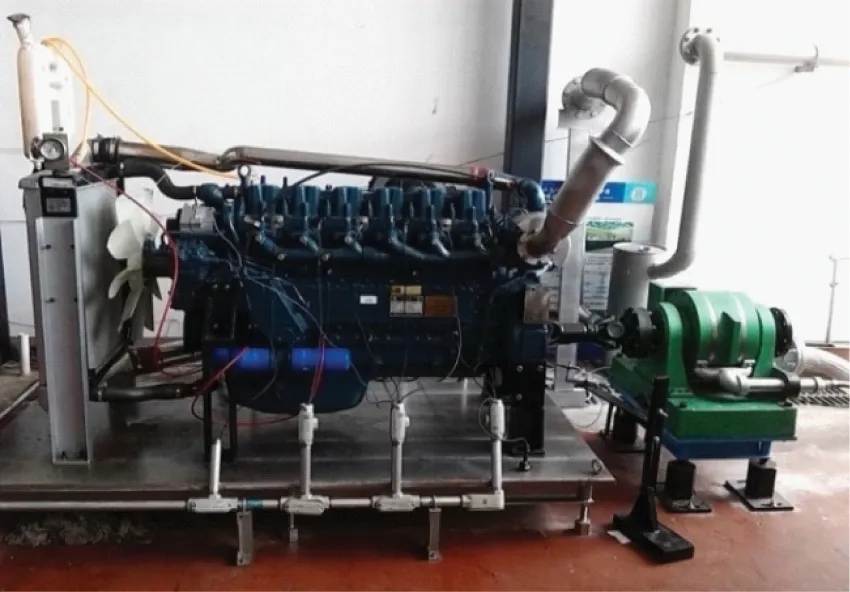
Fig.1 The diesel engine experiment platform

Fig.2 The internal mechanisms of the crankshaft and gear transmission system
Action forces between two gears are equal but in opposite direction when they mesh and work in a stable condition normally. T1is defined as the torque of the crankshaft gear. The load of diesel engine crankshaft gear in simulation is about 120000N·mm, which is about 10% of output torque of diesel engine.
T=T1=120000N·mm
(1)
Circumferential force calculation formula:

(2)
Axial force calculation formula is
Fa=Fttanβ=2587.5×tan14°=645.1N
(3)
Radial force calculation formula is
(4)
In conclusion, the resultant force calculation formula acting on the gear is as follows:
(5)
When the crankshaft thrust bearing is worn, if there is an axial force f acting on the crankshaft, axial displacement may appear on the crankshaft thereby causing the crankshaft gear to generate axial displacement along with the crankshaft. There will be a reactive force equal to axial force Fdin the position of the gear contact in order to maintain a balance of the crankshaft.
The wear of the thrust bearing influencing gears meshing state was simulated by changing the axial displacement of the crankshaft, and there is a positive correlation between the axial displacement and the wear of the thrust bearing. Therefore, in the research a dynamic simulation method is used to analyze the effect of thrust bearing wear on the gears meshing force. In order to avoid the problems such as large calculation scale caused by the direct application of the axial contact constraint to the crankshaft and the errors caused by the setting of contact pair parameters, an equivalent method is applied to simulate the wear of the bearing through the axial displacement constraint to the crankshaft.
Setting the crankshaft displacement function as f(x), the crankshaft gear axial force calculation formula is
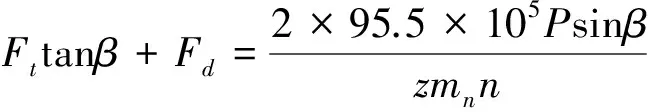
(6)
In normal meshing state f(x)=0, and Fa1=Fa. If crankshaft does not move or reach a new steady state with axial movement, the gear stress will remain unchanged. However, the stress will change because of the shorter contact lines of the helical gears in the new steady state. If the axial acceleration always exists, the gear axial force will change with the law affected by crankshaft axial movement. Meanwhile, when crankshaft movement happens, the gear cannot properly connect with the intermediate gear, causing collision and extrusion. The calculation formula is
(7)
where k is Hertz stiffness coefficient affected by material properties and interface curvature radius, u is collision force exponent, usually equal to 1.5 for steel, δ is normal penetration coefficient and C is equivalent damping coefficient and δ is the normal deformation velocity. With the theory of Hertz:
(8)
E is elastic modulus, reflecting non-linearity degree of the material.
According to the research in Ref.[18], equivalent damping coefficient C is connected with restitution coefficient ε and stiffness coefficient k. The relationship can be expressed as
(9)

Because the input power, output power and rotate speed remain constant, the circumferential force and radial force also remain constant. So the resultant force acting on the gear is
(10)
Therefore, when the crankshaft thrust bearing is worn, the crankshaft will drive the axial displacement of the gears, and the connection between gears will be out of the normal state. This will cause the emergence of shock, extrusion and other phenomena, which will result in a sharp increase in the force on the gears. Meanwhile, the two gears are in bad meshing relations, the vibration will be caused by moment and torque, which can be detected by vibration transducers installed on the surface of the body of the engine.
2 Simulation and result analysis
2.1 Models of the crankshaft and gears
Firstly, parts entity models are set up and assembled in CREO software; the models are then transferred into ADAMS software to finish the simulation condition setting. The modeling processes are as follows.
(1) In CREO, the tooth profile is established according to the gear geometry size and the relationship of different parameters. Translation and rotation commands based on feature copying are used to create the transverse tooth profile in both sides. The helical gear entity models are established by scan, mix and array commands. The size parameters of the gears are shown in Table 1.
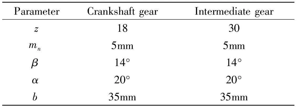
Table 1 Size parameters of the gears
(2) The crankshaft model is established by rotation and extrusion commands. Size parameters of the crankshaft are shown in Table 2.
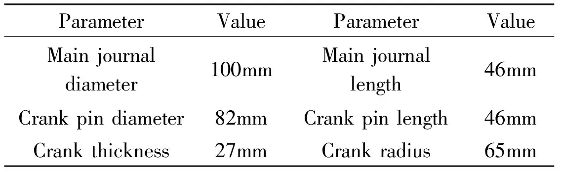
Table 2 Parameters of crankshaft
(3) In assembly mode, the crankshaft is set to the default location, the crankshaft gear is assembled whose axis coincides with the crankshaft axis, an intermediate gear is assembled to coincide with the end face of the crankshaft gear and set the center distance to the theoretical calculation value. The correct meshing relation of the intermediate gear and the crankshaft gear should be assured.
(4) There are lots of mode formats imported to ADAMS software. Parasolid file has the best compatibility among them. Therefore, the model assembled in CREO as x_t format is saved, then it is imported to ADAMS.
(5) Set the component parts material property as “Steel”.
(6) Set up the connectors, motions and contacts. Set a cylindrical joint between the crankshaft and the ground, a fix joint between the crankshaft gear and the crankshaft. Then set a revolute joint between the intermediate gear and the ground, a contact is set between the two gears. The motions include the crankshaft speed and axial displacement. Meanwhile, setting an opposite torque on the intermediate gear as the load.
(7) Choose a solver and set simulation time, step size and steps. Then making iterative solution.
In order to reduce calculation and save time, the models will be simplified. There are no crankshaft oil holes, chamfering and keyway. Since the main analysis object is the tooth stress of gears, the structure of wheel has also been simplified. The established models in software is shown in Fig.3.

Fig.3 The models in software
2.2 The contact parameters of calculation
In ADAMS the main parameters that are required are stiffness coefficient k, collision force exponent n, damping coefficient C and penetration coefficient δ. According to the Hertz contact theory:
(11)
(12)
where R1, R2are the equivalent radius of contact bodies in contact respectively. The reference radius is set as the equivalent radius. R1=46.1mm, R2=76.85mm.
(13)
All material of gears is 45# steel, so, μ1=μ2=0.29, E1=E2=207GPa; k=8.09×10⁵N/mm. The other parameters can be set based on experience at u=1.5, C=10, δ=0.05mm.
2.3 Simulation condition
Crankshaft speed is 1500rpm, the load is 200Nm, the simulation time is set to 5s and the sampling frequency is 1000Hz. The displacements are 0mm, 0.3mm and 0.5mm. The operating condition of unidirectional movement of the crankshaft is simulated. The crankshaft has moved to a certain position on one side of the gearbox. Crankshaft unidirectional movement is very common in reality, and can lead to bush-burning of the thrust bearing, the failure of gears and wear of main bearings.
2.4 Reliability of the simulation results
The stress on the gear surface is analyzed. The simulation model is a rigid body model, and there is a certain deviation between the calculation result and the simulation result. The reference value of the simulation result can be judged through the result that whether the effective value of the force in the non displacement group is close to the theoretical value. The above calculation parameters are the same as the simulation setting parameters and the theoretical calculation and in normal working conditions, the stress of gear is 2837.8N, and the value is close to the effective value of non displacement simulation result of 2722N. Therefore, it can be considered that the simulation result is in the error tolerance range.
2.5 Analysis of the simulation results of unidirectional motion
Through the simulation, the contact force on the transmission gears under 0mm, 0.3mm and 0.5mm axial displacements with unidirectional movement conditions are obtained, shown in Fig.4, Fig.5 and Fig.6.
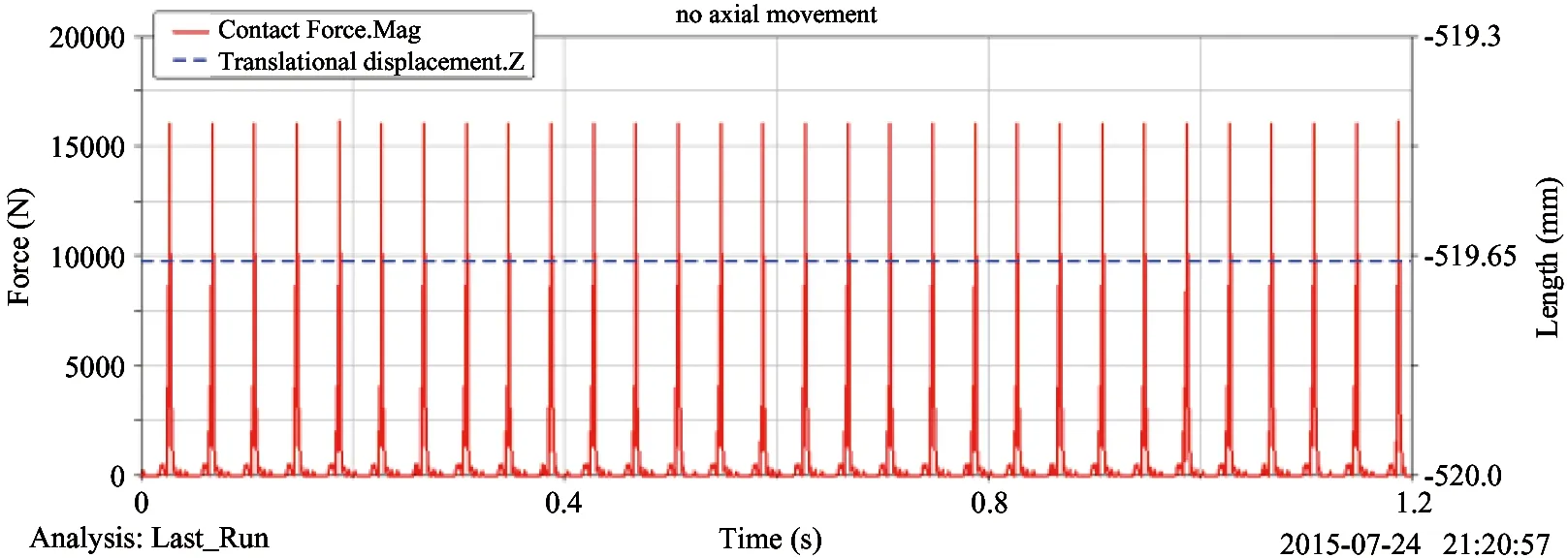
Fig.4 The contact force on the transmission gears with 0mm
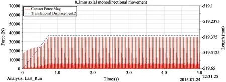
Fig.5 The contact force on the transmission gears with 0.3mm

Fig.6 The contact force on the transmission gears with 0.5mm
Comparing the contact forces on the gear of unidirectional displacement with those of normal working condition, the force will increase as the displacement increases, as shown in Fig.7. The result can be observed in Table 3. Taking the Fourier transform of the force signals of the gear, the frequency spectrums are obtained in Fig.8 to Fig.10. It can be observed that the components of the crankshaft gear rotating frequency and each order frequency multiplication increase as the displacement increases. The main frequency components are shown in Table 4.
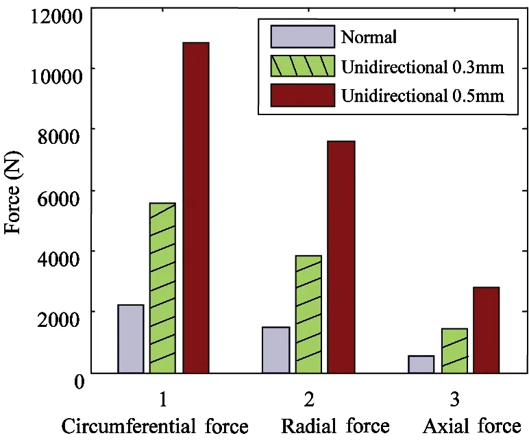
Fig.7 Gear load contrast diagram

ThecontactforceMaximumvalueAveragevalueEffectivevalueNormal16173N767N2722NUnidirectional0.3mm34893N2795N6921NUnidirectional0.5mm63190N6463N13523N

Fig.8 Frequency spectrum of contact force data with 0mm
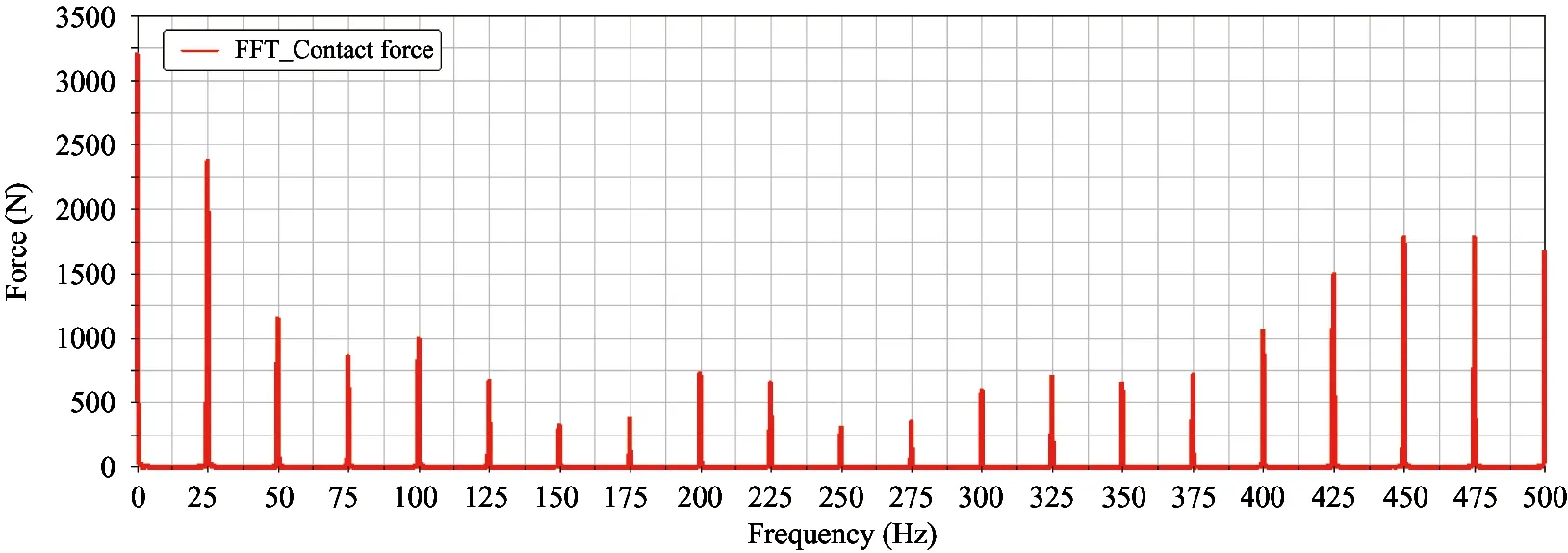
Fig.9 Frequency spectrum of contact force data with 0.3mm
The forces of the gear are decomposed into the circumferential, radial and axial directions as shown in Table 5. This highlights that all three reverse forces increase, with the radial force becoming the largest. The forces of the three directions of the gear are not in accordance with the above equations, therefore, the size and the direction of the gear forces are changed. After unidirectional displacement has reached a new steady state, gear stress will increase mainly due to the transmission ratio of the driven wheel and the driving wheel remains unchanged in simulation process. The axial movement of the crankshaft causes the squeeze of thetwo gears, which will lead to a great collision based on the collision force theory in the second section of this paper. This is the primary cause of rapidly increased gear stress. In reality, the driving wheel speed and the driven wheel speed in the movement process cannot maintain the same proportion. The speed fluctuation and vibration will appear until the gear reaches a new stable operation state. After reaching the steady state, the force of the gear will not increase sharply. However, the process of vibration and slippage have an impact between teeth and teeth. The higher the speed, the bigger the impact. This may lead to fracture on the gears.
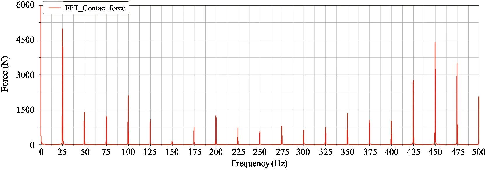
Fig.10 Frequency spectrum of contact force data with 0.5mm
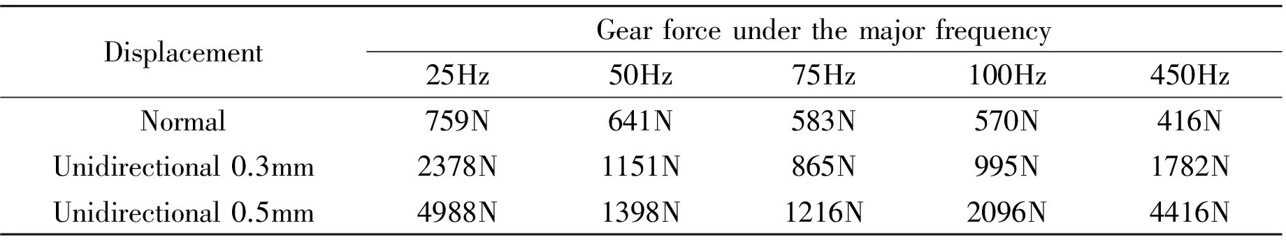
DisplacementGearforceunderthemajorfrequency25Hz50Hz75Hz100Hz450HzNormal759N641N583N570N416NUnidirectional0.3mm2378N1151N865N995N1782NUnidirectional0.5mm4988N1398N1216N2096N4416N
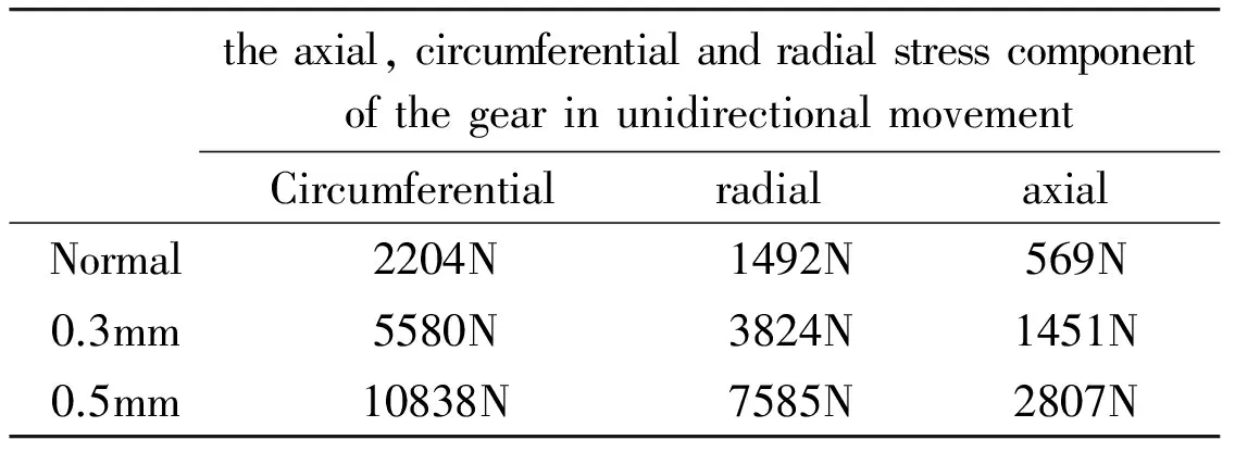
Table 5 The force on the gear in unidirectional movement
3 Validation study
Since it is hard to simulate engine crankshaft thrust bearing wear and fault, in addition it is also difficult to research the influence of crankshaft motion on engine gears through experiment, research is made on the fault diagnosis method of gears after the crankshaft thrust bearing wear of a real case.
The engine is a V-shaped-16-cylinders diesel engine, the rated speed is 1500rpm and rated output is more than 3000kW. Online monitoring system comprising following transducers: accelerometer, proximity probe and key-phase transducer is installed on the engine. These transducers record the faults in data during different periods. There are sixteen acceleration transducers installed on the cylinder, four on the crankcase and one on the gearbox. It can achieve online monitoring of the vibration of cylinders, crankcase and gearbox. The transducers installation diagram is shown in Fig.11. During running, the crankshaft axial displacement occurs because of the wear of crankshaft axial thrust bearing, which triggers fracture failure of gear in the gearbox. The engine inspection and maintenance results are shown in Fig.12. The online monitoring system captures the signals of the fault.
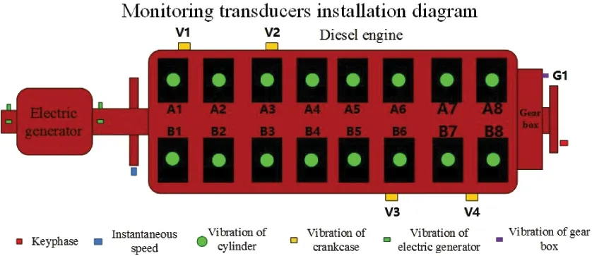
Fig.11 The transducers installation diagram of the diesel engine
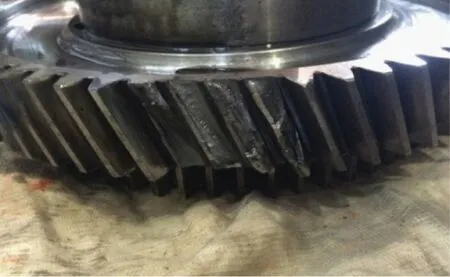
Fig.12 The broken gear of the diesel engine
Fig.13 and Fig.14 are the vibration data of the crankcase and gearbox of the engine monitored by the transducers. It can be observed from the historical trends shown in Fig.13, that at approximately 4:00 am on August 17, 2014, at V4 point of the crankcase vibration and G1 point of gearbox axial vibration are increasing rapidly at the same time. As can be seen from the figure, the maximum vibration RMS values are respectively over 50mm/s and 900mm/s.
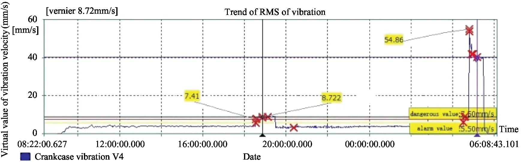
Fig.13 Vibration trend of diesel engine crankcase
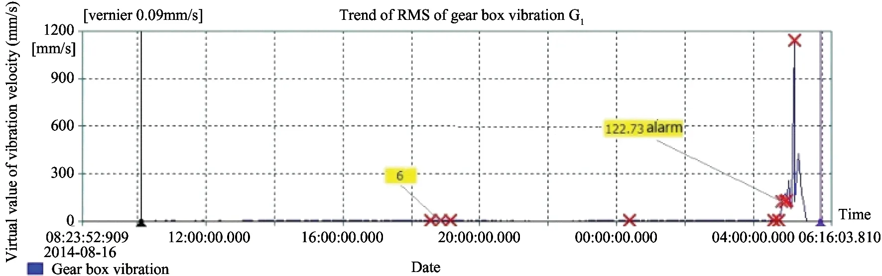
Fig.14 Vibration trend of diesel engine gearbox
Fig.15 and Fig.16 are the vibration frequency spectrograms of gearbox vibration in common and fault conditions. As can be seen from the spectrograms, in the fault, the measured vibration peak value of 25Hz, 75Hz and 150Hz are significantly increased. These are similar to the simulation results of the above theoretical models.
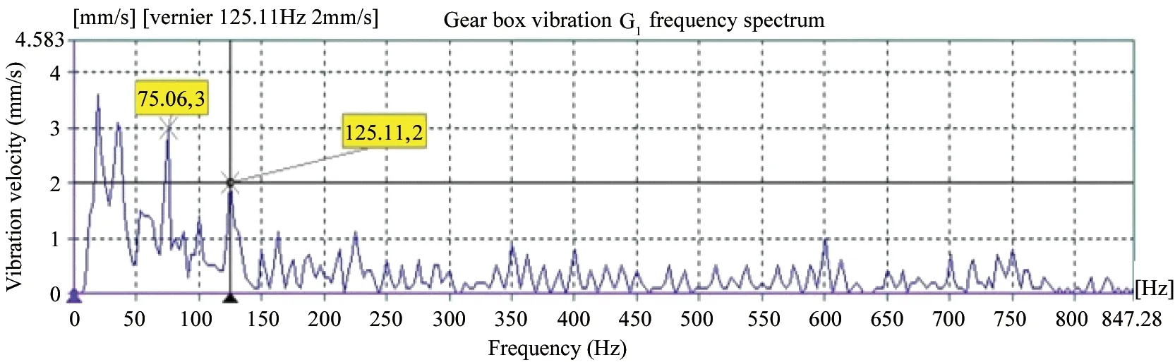
Fig.15 Vibration frequency spectrogram of diesel engine gearbox in normal

Fig.16 Vibration frequency spectrogram of diesel engine gearbox in fault
4 Conclusion
This study focuses on the regularity of the force on the gear in a piston engine with crankshaft axial movement. The simulation results prove that the axial displacement of the engine crankshaft will seriously influence the safety and stable operation of the engine; in addition it causes increased stress on the gear. This could lead to shock vibration and fracture of gear even misfire and fracture of connecting rod. The conclusions are as follows:
(1) From the graph of gear contact force and time, it can be obtained that the unidirectional motion of the crankshaft will cause increased load on the gears. The load is proportional to the displacement.
As shown in Table 3, the effective value of load under 0.3mm displacement increases to 2.542 times of that in normal, and the effective value of load under 0.5mm displacement increases to 4.968 times of that in normal, which will lead to overload and breakage of the gear teeth.
(2) From the spectrum graphs of gear contact force, it can be found that with the displacement increasing, different frequencies of the contact force are increasing accordingly.
(3) Through the analysis of actual engine fault data, theoretical simulation results and the actual fault signal feature has a good consistency. In the fault of the wear on crank thrust bearing, the gears of the engine will be broken and the vibrations of engine crankcase and gearbox will increase significantly. Analyzing the vibration signal frequency components, vibration values of rotating frequency and frequency multiplication increase significantly.
Therefore, the actual operation of the engine can be monitored by online monitory system through measuring vibrations of crankcase and gearbox. Based on vibration feature extraction and analysis of time domain and frequency domain signals, it can effectively capture the characteristics of the gear faults under crankshaft axial movement condition.
[ 1] Sun J, Fu Y, Deng M, et al. Study on design optimization of a crankshaft bearing considering crankshaft strength for an internal combustion engine. Proceedings of the Institution of Mechanical Engineers Part J Journal of Engineering Tribology, 2009, 223(6): 919-924
[ 2] Fontanesi S, Giacopini M. Multiphase CFD-CHT optimization of the cooling jacket and FEM analysis of the engine head of a V6 diesel engine. Applied Thermal Engineering, 2013, 52: 293-303
[ 3] Sellerbeck P, Nettelbeck C, Heinrichs R, et al. Improving diesel sound quality on engine level and vehicle level-a holistic approach. SAE paper, No.2007-01-2372
[ 4] Li W, GuF S, Andrew D B, et al. A study of the noise from diesel engines using the independent component analysis. Mechanical Systems and Signal Processing, 2001, 15: 1165-1184
[ 5] Tamminen J, Sandstrom C E, Andersson P. Influence of load on the tribological conditions in piston ring and cylinder liner contacts in a medium-speed diesel engine. Tribology International, 2006, 39(12): 1643-1652
[ 6] Jahansson S, Frennfelt C, Killinger A, et al. Frictional evaluation of thermally sprayed coatings applied on the cylinder liner of a heavy duty diesel engine: pilot tribometer analysis and full scale enginetest. Wear, 2011, 273: 82-92
[ 7] Senecal P K, Reitz R D. Simultaneous reduction of engine emissions and fuel consumption using genetic algorithms and multi-dimensional spray and combustion modeling. SAE paper, No. 2000-01-1890
[ 8] Wickman D D, Senecal P K, Reitz RD. Diesel engine combustion chamber geometry optimization using genetic algorithms and multidimensional spray and combustion modelling. SAE paper, No. 2001-01-0547
[ 9] Shrivastav R, Hessel R, Reitz R D. CFD optimization of DI diesel engine performance and emissions using variable intake valve actuation with boost pressure, EGR and multiple injections. SAE paper, No. 2002-01-0959
[10] Abdelaal M M, Hegab A H. Combustion and emission characteristics of a natural gas-fuelled diesel engine with EGR. Energy Conversion and Management, 2012, 64: 301-312
[11] Wang X J, Cai Y P, Lin X Z. Diesel engine PT pump fault diagnosis based on the characteristics of its fuel pressure. Ieri Procedia, 2014, 7:84-89
[12] Tamura M, Saito H, Murata Y, et al. Misfire detection on internal combustion engines using exhaust gas temperature with low sampling rate. Applied Thermal Engineering, 2011, 31:4125-4131
[13] Li Y, Tse P W, Yang X, et al. EMD-based fault diagnosis for abnormal clearance between contacting components in a diesel engine. Mechanical Systems & Signal Processing, 2010, 24:193-210
[14] Geveci M, Andrew W O, Franchek M A. An investigation of crankshaft oscillations for cylinder health diagnostics. Mechanical Systems & Signal Processing, 2005, 19:1107-1134
[15] Liu S, Du R, Yang S. Fault diagnosis for diesel engines by wavelet packet analysis of vibration signal measured on cylinder head. Journal of Vibration Engineering, 2000, 13(4): 577-584 (In Chinese)
[16] Jin M, Jiang Z N. A new feature reduction method and its application in the reciprocating engine fault diagnosis. Wseas Transactions on Signal Processing, 2012, 8(2): 54-63
[17] Jiang Z N, Zhang J J, Jin M, et al. An expert system based on multi-source signal integration for reciprocating compressor. WSEAS Transactions on Systems, 2013, 12(5): 266-279
[18] Lankarani H M, Nikracesh P E. Continuous contact force model for impact analysis in multi body systems. Nonlinear Dynamics, 1994, 5: 193-207
Yao Ziyun, born in 1978, is studying for his Ph.D degree in Diagnosis and Self-recovery Engineering Research Center of Beijing University of Chemical Technology. His research interests focus on piston engine fault diagnosis and expert system.
10.3772/j.issn.1006-6748.2016.04.012
① Supported by the National Basic Research Program of China (No. 2012CB026000), the Beijing Municipal Science and Technology Commission Program (No. Z131100004113004) and the Fundamental Research Funds for the Central Universities (JD1506).
② To whom correspondence should be addressed. E-mail: zjj87427@163.com Received on May 31, 2016*
 High Technology Letters2016年4期
- High Technology Letters的其它文章
- Fuzzy image restoration using modulation transfer function①
- Fluid simulation of internal leakage for continuous rotary electro-hydraulic servo motor①
- A buffering method for quadruped robots based on active impedance control①
- Research of refrigeration system for a new type of constant temperature hydraulic tank①
- Clustering approach based on hierarchical expansion for community detection of scientific collaboration network①
- Measurements and analysis at 400MHz and 2600MHz in corridor radio channel①