A buffering method for quadruped robots based on active impedance control①
Liu Bin (刘 斌), Rong Xuewen
(School of Control Science and Engineering, Shandong University, Jinan 250061, P.R.China)
A buffering method for quadruped robots based on active impedance control①
Liu Bin (刘 斌), Rong Xuewen②
(School of Control Science and Engineering, Shandong University, Jinan 250061, P.R.China)
Compared with wheeled or tracked robots, legged robots exhibit advantages on agile locomotion and higher survival chance for deadly impacts. A buffering strategy is proposed for quadruped robots with non-extreme initial attitudes from the end of air-righting to the steady standing on the ground. This approach consists of landing phase, buffering phase and recovering phase. The variable stiffness control, proportional-derivative(PD) force control and foot trajectory planning are applied to the joints of quadruped robots until the end of the recovering phase. The PD parameters are tuned according to the desired performance of each phase. The above approach is verified on a virtual platform.
quadrupled robot, buffering strategy, position control, force control, variable stiffness-damping control
0 Introduction
Much attention has been paid to legged robots for their adaptability in unstructured environment[1]. However, facing with most unexpected situations, legged robots are still more awkward than legged animals such as falling from high places. While a robot falls on the ground, deadly impact may cause great damage to its mechanism structure, but many animals can protect themselves in this situation. A cat can adjust its body to the proper attitude in falling[2,3]. This phenomenon known as the “cat righting reflex” or “air righting (reflex)” was firstly stated in 1969 by Kane and Scher and a dynamic model of the falling cat had been established[2]. As the air righting reflex is further studied, geckos have also been largely investigated including strategies for air righting and the role of tailsin falling[3,4]. A gecko robot was developed by a team led by J. Robert Full from UC Berkeley. When falling from upside down, this robot can adjust its body to the normal stand-up attitude in the air[5]. A small scale robot with two DOFs was also invented by UC Berkeley. Through the torso adjustment in the three directions, air righting can be done with more flexibility[6]. Zhao, et al.[7]assembled a small-scale robot, which can achieve jumping and air righting using a single actuator. However, these studies only emphasized the air-righting issue without consideration of landing impact of robots.
In addition, the contact forces can be significantly reduced by the buffering structure of kangaroos’ and antelopes’ legs. The buffering structure is viewed as a spring by many researchers[8]. In 1986, the theory of three-period of hopping based on SLIP model is proposed by Raibert, where the landing issue is firstly presented independently. Also a legged hopping robot was assembled based on this theory[9,10]. To guarantee both accuracy and compliance, force control and position control were adopted separately by Sasahara and Motoi on one joint according to the motion status of the robot[11]. Chen, et al.[12]proposed a legs attitudes determination method, allowing easy determination of legs attitudes to achieve good motion performance under different landing conditions. This method can guide the control of six legs of the bionic jumping robot to adapt to rough terrain. PBot was designed and assembled by POSTECH[13], which can fall from a height of 50 cm and land as what a human does. However, for hopping robots, because of the existence of taking off process, the robots’ torso attitudes should be adjusted before leaping.
This paper investigates how to relieve the heavy impact when a quadruped robot falls down and hits the ground. Through modeling and kinematic analysis, a buffering strategy is proposed to protect the robot when falling from a high place (about 2.5m). The following of this paper is organized as: assumptions and modeling, kinematic model, motion phase analysis, control approaches, simulation and results and conclusion.
1 Assumptions and modeling
The overview of the robotic models including both robot system and leg structures are shown in Fig.1.
As shown in Fig.1, the legs are numbered as 1~4. The vectors of them are respectively marked from AAfto DDf, which are shown in Fig.1(a). The relevant hips are marked as hipi(i=1, 2, 3, 4). When the ith leg hits the ground, the contact point is marked as fti. Number i coincides with the ith leg. Each leg has three joints.There are two rotational joints on the hip used for abducting and adducting the legs. The other one is a transitional joint used for contracting and protracting the leg. Taking leg number 4 as an example, the detailed information of its structure is illustrated in Fig.1(b), where the joint structure of the leg and the simplified model are shown.The upper joint (marked as 1) rotates about axis x of the body frame {Ob}, and lower joint 2 rotates about axis y of the body frame {Ob}. All the directions of rotation and the angles in this paper obey the right-hand rule.
To simplify the calculation and analysis, here, r equals to zero and the depth of the torso is ignored. The attitude of the torso is represented by Euler angles, in Z-Y-X order.
To simplify the calculation, some assumptions are shown as follows:
• Compared with the torso, the moments of the legs can be neglected.
• The mass of the torso is uniformly distributed.
• Once a foot hits the ground, no relative movement exists between the foot and the ground and it will not bounce up again.

Fig.1 The overview of the robot model
2 Kinematic model
In this model, the body (local) frame is shown in Fig.1(a). It is located at the geometric center (also the mass center) Obof the body and axis x and axis y are respectively along the directions of CA and BA. Axis z of the body frame points upward, vertical to the torso plane. The orientation of the global (reference) frame coincides that of the body frame in stand-up attitude. However, the origin of the global frame may be different in different phase which will be discussed in the control approaches.
The center of mass (COM) of the torso is Ob, whose coordinate is [xbybzb]. For the ith leg, it is defined
• θxi-the joint angle of the leg about axis x in the body frame
• θyi-the joint angle of the leg about axis y in the body frame
• li-the free length of the leg.
In the body frame {Ob}, with the rotation directions mentioned above, the positive direction of transition is along the negative direction of axis z of the body frame.
According to Fig.1(b), from O2to O1, the D-H parameters of the leg are shown as Table 1.

Table 1 D-H parameters of a single leg
The coordinate of ftirepresented in {Ob} is defined as fbi, and
[fbi1]=Ti·[li001]T+hbi
(1)
where hbi=[hbxihbyihbzi] is the hip coordinate of ith leg represented in body frame {Ob}, and the z component of hiis always zero. According to Eq.(1), the detailed form of the kinematics formula of ith leg is demonstrated as
(2)
Suppose the coordinate of ftiin body frame, namely fbi, is defined as [xyz], Eq.(2) can be rewritten as
(3)
Solving the series of Eqs(3) yields the inverse kinematics of a leg that is shown in
(4)
Considering the uniformity, the forward kinematics of other legs can be achieved as
(5)
and the inverse kinematics are
(6)
Through the forward and inverse kinematic formula, a relationship between the positions of the end effectors and the joint angles has been established. For the robot, the torques will be applied directly on the joint actuators, and through Eqs(5) and (6), the input torques can be achieved.
3 Motion phase analysis
For each single leg, its behavior in the whole process can be divided into three phases: the landingphase, the buffering phase and the recovering phase, which is similar to hopping[12]. These three phases are switched according to the length and the velocity of the leg, which are depicted in Fig.2.

Fig.2 Illustration of the three phases of a leg
3.1 Landing phase
The landing phase starts from the very beginning of the whole process to the moment the leg touches the ground. The mission of this phase is to get ready for landing. Just as the assumption mentioned previously that the total angular momentums of all the four legs are much less than that of the torso about the three axes.Thus, in this phase, the torso attitude will not be affected by the movement of the legs. Besides, a reasonable attitude is needed to maximize the cushioning distance, and minimize the slippery between the feet and ground.
3.2 Buffering phase
The buffering phase lasts from the end of the landing phase to the moment that the leg has been compressed to the shortest. Here, contact1, contact2, contact3and contact4are defined respectively to indicate the contact situations of leg1, leg2, leg3and leg4. When ith leg is in contact with the ground, the “contacti” is non-zero.Otherwise, the value is zero (i=1, 2, 3, 4). The buffering distances are dependent on the lengths of the legs.
3.3 Recovering phase
In recovering phase, the leg length changes from the shortest to original. The robot gradually stands up to the desired (final) configuration. Given the close relationship between the torso and the legs in this phase, when all the legs are in the right configurations, the torso’s attitude will be acceptable. Thus it’s only needed to guarantee the attitudes of the legs so that the calculation can be simplified. To make the system stable, the final attitude of torso will be WX=0, WY=0, WZ=0. WX, WY, WZ that indicate respectively the attitude angles of the torso about axis x, axis y and axis z (in Z-Y-X order) in the body frame.
The whole process of the ith leg (i=1, 2, 3, 4) can be concluded as
(1): contacti≠0

Here, t is the moment of sampling and Δt is the sampling cycle.
4 Control approaches
Deadly impact may greatly damage the mechanism structure of the robots. In 1985, Zheng firstly established a mathematic model of robot collision with the environment and quantatively analyzed the change in joint rates and the change in the external forces[14]. In animals, the impact can be filtered by their muscles. Muscles are known as being with the character of variable stiffness[15]. Joints (actuators) with variable stiffness, known as VSA, will minimize the impact forces in collisions[16]. Yu, et al[17]invented a rehabilitation robot driven by a novel compact series elastic actuator. Its control scheme enables the robot to achieve low output impedance when operating in human-in-charge mode and achieve accurate force tracking when operating in force control mode.Compliance control and adaptive position/torque control based on series elastic actuators (SEA) were applied on a hopping-legged robot in Ref.[18] to avoid delay and limited bandwidth in position control.
According to Ref.[19], this view can also be used in legged robots.
With the structures of the legs shown previously, each leg has three DOFs, and the input of the ith leg can be represented as
Ii=[TxiTyiFli]
(7)
where, Txiand Tyi, determined by θxiand θyi, are respectively the torques applied on the rotational joints about axis x and axis y of the body frame. Here, both θxiand θyiare represented in the body frame. Fliis the force applied on the transitional joint to control the length of the leg and its value depends on l0i——the desired length of the ith leg.Also, in the body frame, θ0xiis the desired angle of the leg about axis x, and θ0yi, the desired angle of the leg about axis y.
In the whole process, to make the best use of lengths of legs and to minimize the possibility of slippery, a motion plan is used to guarantee the accuracy of the legs’ landing postures. Also to achieve the best effect of buffering, the PD force control with varying PD parameters is applied to the transitional joints to improve the compliance. The form of applied force on the ith leg can be described as
Fi=Kp·(l0i-l)-Kd·dl/dt
(8)
where Kpand Kdare about to be changed according to the desired performance. The control on the transitional joints can be viewed as choosing the optimal PD parameters, and the choice of PD parameters is based on our experience, so what really matters here is to deal with the motion planning of the rotational joints.
4.1 Landing phase
In the landing phase, all legs are in the air. The robot’s behavior in this phase is crucial to its stability in the following phases. To utilize the lengths of the legs to the maximum, the distance between the foot and the relevant shoulder should be as long as possible. So like a cat, the legs of the robot point down vertically to get the maximum buffering distance.
In the kinematic model, the feet and the corresponding hips are of the same coordinates in x and y components in the global frame and the body frame. And the control input is given according to the inverse kinematics figured above. If the inertia of the legs are taken into consideration, in this phase, the swinging of the legs may affect the attitude of the body depending on the ratio of inertia between the torso and the legs. This article mainly focuses on the buffering strategy when the torso is not in extreme attitude. As is mentioned in assumption 1, the change in torso attitude is very small and can be simply neglected.
According to the forward kinematics model, the vectors of the four legs described in body frame are respectively fb1~ fb4and the hips described in the body frame are defined as hb1~ hb4.
The attitude of the torso is represented in Euler angle (Z-Y-X order), and the matrix transforming from body frame {Ob} to global frame {O} is
(9)
where Rot is the rotation matrix from frame {Ob} to frame {O} and i is the number of the leg, i=1,2,3,4.
The coordinate of the ith leg represented in the global frame is
(10)
and the coordinate of hipiin the global frame is
(11)
Accordingly, to maintain the leg’s vertical attitude, it can be seen that
(12)

With WX and WY are given by sensors, by solving Eq.(12), θxiand θyican be achieved and they are the desired control inputs of θ0xiand θ0yiof each leg.
4.2 Buffering phase
In this phase, the legs that have been in contact with the ground are called the landing legs and the others are called the swinging legs.According to assumption 3, once a leg touches the ground, the contact point is fixed, i.e.all legs need to land at proper contact points. Here the “proper contact points” are called the desired contact points, or DCPs for short. The DCPs are determined by the configuration of the robot and detailed information will be discussed later. All the corresponding definitions have been depicted in Fig.3.
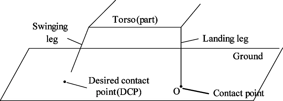
Fig.3 Illustration of definitions in landing phase
The general control strategy of this phase is stated as follows.
When the foot-ground contact is detected,the landing legs maintain vertical to the ground, and the swinging legs reach the DCPs until all feet land on their desired positions.Here, the reference frame (global frame) is set at the contact point of the foot tip of the first landing leg, with the above mentioned orientation. For the situations that more than one legs touch the ground simultaneously, there are several measures to set the reference frame, but here the contact point of the feet with the smallest number is chosen to be the original of the reference frame.
Suppose, in reference frame, dojis defined as the DCPs’ coordinate of leg j(j=1, 2, 3, 4) and the origin of the reference frame is at the foot tip of legi (O in Figure 3), i≠j. dojis transformed from the reference frame to the body frame, the coordinate of DCP represented in body frame is shown as
dbj=bTo·doj
(13)
The hip joint angles θxand θyfor a swinging leg can be achieved using Eqs(6) and (13).
4.3 Recovering phase
In this phase, the system adjusts the torso to the right attitude. According to the previous statement, the final body attitude should be WX=0, WY=0, WZ=0.
To obtain the final status, all the final attitudes of the legs need to be vertical to the ground with the same length (here, free length).
Here all four legs touch the ground. The torques on the hips are set to make sure that all the legs are vertical to the torso normal, and the forces applied on the legs are set to make sure that the legs are all at desired length.
τxi=Ktpx·(θ0x-θx)-Ktdx·dθx/dt
(14)
τyi=Ktpy·(θ0y-θy)-Ktdy·dθy/dt
(15)
where θxand θyare given by sensors relatively to the body frame. Ktpxand Ktpyare the joints’ stiffness, and Ktpyand Ktdyare the joints damping.
According to Eq.(5), through detailed-considered PD parameters, proper joint input Iican be achieved.
Also, in the whole process, the stiffness and damping of the transitional joints are stated as follows.
During the whole process, proper PD parameters are required. For PD force control, it is very difficult to find the optimal parameters. In this paper, three sets of PD parameters are chosen for each phase of the legs. In the landing phase, no contacts exist between the robot and environment and the masses of the legs are negligible. So there is no external force applied on the robot in this phase. To resist the slight turbulence during falling process, Ps and Ds are set very small. In the buffering phase, to reduce the impact, the Ps and Ds should significantly increase. On one hand, the PD parameters should not be as large as possible because the parameters of too large values may not be beneficial for maximizing the buffering distance. On the other hand, the PD parameters should not be small in case the torso of the robot hits the ground. So a compromise is needed in determining the PD parameters. In the recovering phase, Ds play a more important rule. The damping of the joints should be large enough to make sure that the robot is an over damping system to prevent the robot bouncing up from the ground. In views of these, the Ps and Ds can be determined and the parameters shown in Table 2 are proven acceptable.
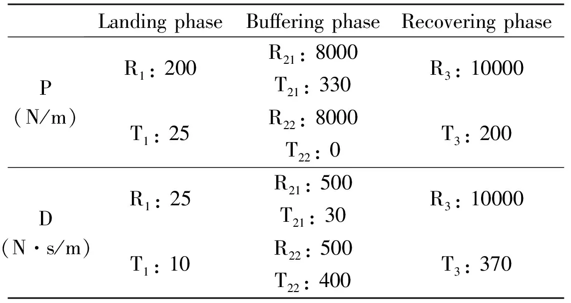
Table 2 PD parameters of the joints
It should be noted that the three phases mainly focus on the first landing leg/legs. When the first leg/legs touch the ground, some other legs may still in their landing phase, but their joint inputs have been changed (reaching for their DCPs). So here, the three-phase period can only be as a reference for the swinging legs, because the behavior of these legs may not be exact as previously mentioned.
The overall control frame of the robot is shown in Fig.4.
The robot outputs each legs’ velocities of the three joints. The phase can be detected by the “State Detection” according to the parameters.
The “state detection” in Fig.4 can be illustrated in Fig.5 (the leg number is i). The “contact” in Fig.5 is defined as contact=contact1& contact2& contact3& contact4.

Fig.4 The overview of the control system
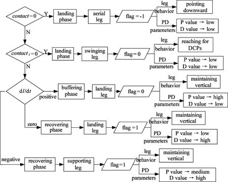
Fig.5 The detailed information of “state detection”
5 Simulation and results
According to what has been stated above, a virtual prototype is developed in Robot Builder, which is viewed as our simulation environment. The robot and its initial attitude are shown in Fig.6. The acceleration of gravity g is 9.81m/s2pointing downward. The size of the torso is 1000mm×500mm×10mm, and its mass is 20kg. The free length of each leg is set to 1000mm with their final directions vertical to the torso plane.

Fig.6 The virtual robot in the experiment in initial status
In this simulation, the robot freely falls from a height of 2.5m above the center of gravity (COG) of the torso to the ground. In initial, the body frame rotates π/6 about axis x of the body frame.
Table 2 illustrates the PD parameters of joints. “R”and “T” denote the rotational joints on the hips and the transtional joints on the knees, respectively. The subscripts indicate the motion phase of the robot. Subscript 1 means the landing phase and subscript 3 means the recovering phase. The buffering phase can be divided into two parts. Subscript 21 indicates the first part, lasting from the buffering phase starts to the velocity of the transitional joint on the leg equals to zero. And subscript 22 indicates the second part, namely, the remaining part of the buffering phase.
Through observing the performance of the robot, the PD parameters in other phase can be determined.
The effects of the buffering strategy are shown in Fig.7~Fig.9.
• Fig.7~Fig.9 demonstrate the results of buffering in the angular and linear accelerations of the torso,
as well as the contact forces of the legs, respectively.
• The part “a” in each figure indicates the buffering effects using the approach in this article. And the part “b” in each figure indicates the same situation without any buffering measure.
• The accelerations in Fig.7 and Fig.8 are measured at the COM of the torso and they are represented in the body frame.
According to Fig.9, the final contact force on every single leg is about 51N, which is about a quarter of the gravity of the whole robot, which means that the robot stably stands on the ground finally.
The maximum instantaneous angular accelerations and the maximum instantaneous linear accelerations on the torso mass center are significantly reduced compared with contrast groups. The horizontal axis indicates the time, and the unit is second (s). For the simulation without buffering, it is hard for the robot to stand stably. However, to demonstrate the maximum impact during the whole process, the first two seconds are requried. The locomotion of the robot is symmetrical along axis y, which means leg 2 and leg 4 will hit the ground simultaneously and then leg 1 and leg 3 will touch the ground simultaneously.
In part “(a)” of all the Fig.7~Fig.9, the impulses are mainly caused by the switches in motion phases.
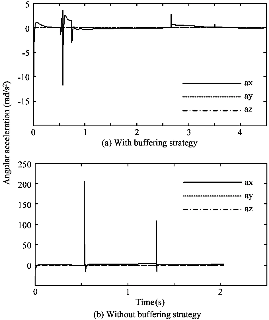
Fig.7 The angular accelerations of the torso COM

Fig.8 The linear accelerations of the torso COM

Fig.9 The contact forces on the feet
In part “(b)” all the Fig.7~Fig.9, the impacts without any buffering approach are illustrated. Obviously, these impacts are fatal to the robot.
Taking leg 1 as an example, the force applied on the transitional joint of leg 1 is illustrated in Fig.10. From the figure, the three motion phases can be seen clearly. (1), (2) and (3) in the figure respectively indicate the landing phase, the buffering phase and the recovering phase.
That can be seen from the figures, the robot with the buffering strategy lands with more compliance.The instant angular accelerations and the linear accelerations are reduced greatly through buffering and the contact forces were also reduced.

Fig.10 The force applied on leg 1
6 Conclusion
According to the simulation, the initial height from the torso mass center to the ground is 2.5m and the torso mass is 50kg. Some conclusions are as follows.
Firstly, the impact resulting from landing can be reduced significantly through the buffering strategy in this article. The peak instant linear acceleration of the torso mass center along axis z of the global frame reduced from nearly 200g to about 3g (g is the acceleration of the gravity), equivalent to what a person feels on a roller coaster[20]. The peak contact force on the feet along axis z of the global reduced from 1.2×10⁴N to about 250N. For human beings, when walking, the knees would take more than three times the body weight. The knees of the robot in this paper only took about 1.27 times the torso weight, which would not cause damage to the robot.Besides, the peak instant accelerations along and about other axe were also significantly reduced. This is the main contribution of this study.
Secondly, this approach mainly focuses on the situation of free fall. And falling with a vertical velocity can also be available because falling with a vertical velocity can be equivalent to falling freely from a different distance. However, once the lateral velocities cannot be ignored, this approach needs to be improved for buffering the impact on horizontal direction when the feet touch down on the ground.
Finally, the touch-down period is very short, so a high control frequency is necessary. In this simulation, the control frequency is 104Hz. It requires higher processing speed for computing systems to realize this approach. Higher bandwidth for the actuators and the sensors are also required. So this approach has not been applied on a real robot at present. In the future, a combination of active and passive compliance will be applied on the robot to lower the difficulties in realizing the approach.
Acknowledgement
The authors gratefully acknowledge the help and discussion provided by Prof. Li Yan from Shandong University. We appreciate all his efforts for this paper.
Reference
[ 1] Li Y B, Li B, Rong X W, et al. Mechanical design and gait planning of a hydraulically actuated quadruped bionic robot. Shandong DaxueXuebao(GongxueBan), 2011, 41(5): 32-36 (In Chinese)
[ 2] Kane T R, Scher M P. A dynamical explanation of the falling cat phenomenon. International Journal of Solids and Structures, 1969, 5(7): 663-760
[ 3] Jusufi A, Zeng Y, Full R J, et al. Aerial righting reflexes in flightless animals. Integrative and Comparative Biology, 2011, 51(6): 937-943
[ 4] Libby T, Moore T Y, Chang-Siu E, et al. Tail-assisted pitch control in lizards, robots and dinosaurs. Nature, 2012, 481(7380): 181-184
[ 5] Full J R. Learning From the Gecko’s Tail. http://www.ted.com/talks/robert_full_learning_from_the_gecko_s_tail: TED, 2009
[ 6] Chang-Siu E, Libby T, Brown M, et al. A nonlinear feedback controller for aerial self-righting by a tailed robot. In: Proceedings of the 2013 IEEE International Conference on Robotics and Automation, Karlsruhe, Germany, 2013. 32-39
[ 7] Zhao J, Xu J, Gao B, et al. MSU jumper: A single-motor-actuated miniature steerable jumping robot. IEEE Transactions on Robotics, 2013, 29(3): 602-614
[ 8] Blickhan R. The spring-mass model for running and hopping. Journal of biomechanics, 1989, 22(11): 1217-1227
[ 9] Raibert M H, Chepponis M, Brown Jr H B. Running on four legs as though they were one.IEEE Journal of Robotics and Automation, 1986, 2(2): 70-82
[10] Hodgins J K, Raibert M H. Biped gymnastics. The International Journal of Robotics Research, 1990, 9(2): 115-128
[11] Sasahara K, Motoi N, Shimono T, et al. Stable landing method for biped robot by using switching control. In: Proceedings of the IEEE International Workshop on Advanced Motion Control, Sarajevo, Yugoslavia, 2012. 1-6
[12] Chen D, Zhang Z, Chen K. Legs attitudes determination for bionic locust robot based on landing buffering performance. Mechanism and Machine Theory, 2016, 99: 117-139
[13] Sung S, Youm Y. Landing motion control of articulated legged robot. In: Proceedings of the IEEE International Conference on Robotics and Automation,Roma, Italy, 2007. 3230-3236
[14] Zheng Y F, Hemami H. Mathematical modeling of a robot collision with its environment. Journal of Robotic Systems, 1985, 2(3): 289-307
[15] Lin A B, Zhou J J, Zhang Y P. Design of joint variable stiffness actuation system of service robot. Journal of Mechanical & Electrical Engineering, 2013,30: 439-443 (In Chinese)
[16] Yang Z Y, Fang D J, Zhang J. Variable stiffness compliant actuator and its application in energy subsidy exoskeleton suit. Journal of Naval Aeronautical & Astronautical University, 2013, 28: 459-465 (In Chinese)
[17] Yu H, Huang S, Chen G, et al. Human-robot interaction control of rehabilitation robots with series elastic actuators. IEEE Transactions on Robotics, 2015, 31(5): 1089-1100
[18] Zhu Q, Mao Y, Xiong R, et al. Adaptive torque and position control for a legged robot based on a series elastic actuator. International Journal of Advarced Robotic Systems, 2016, 13:26. doi: 10.5772/62204
[19] Pratt J E, Krupp B T. Series elastic actuators for legged robots. In: Proceedings of the Defense and Security, International Society for Optics and Photonics,Orlando, USA, 2004. 135-144
[20] Teng R, Wei G, Gao S, et al. Dynamic modeling and simulation of roller coaster. In: Proceedings of the International Conference on Computer Application and System Modeling, Taiyuan, China, 2010. 5: 340-342
Liu Bin, born in 1986. He is now a Ph.D Candidate in Shandong University. He received his B.S. degree from Shandong University in 2011. His research interests include motion control for quadruped robots, impednce control and buffering strategy for legged robots.
10.3772/j.issn.1006-6748.2016.04.014
① Supported by the National High Technology Research and Development Program of China (No. 2015AA042201), the National Natural Science Foundation of China (No. 61233014, 61305130), the Shandong Provincial Natural Science Foundation (No. ZR2013FQ003, ZR2013EEM027) and China Postdoctoral Science Foundation (No. 2013M541912).
② To whom correspondence should be addressed. E-mail: rongxw@sdu.edu.cn Received on Nov. 19, 2015
 High Technology Letters2016年4期
- High Technology Letters的其它文章
- Fuzzy image restoration using modulation transfer function①
- Fluid simulation of internal leakage for continuous rotary electro-hydraulic servo motor①
- Research of refrigeration system for a new type of constant temperature hydraulic tank①
- Clustering approach based on hierarchical expansion for community detection of scientific collaboration network①
- Measurements and analysis at 400MHz and 2600MHz in corridor radio channel①
- A visual awareness pathway in cognitive model ABGP①
