不锈钢筋与混凝土的黏结性能
李承昌,何伟南,芦 杰,耿会涛
(1.交通运输部公路科学研究院,北京 100088;2.绍兴市公路管理局,浙江 绍兴 312035;3.郑州大学,河南 郑州 450001)
不锈钢筋与混凝土的黏结性能
李承昌1,何伟南2,芦 杰2,耿会涛3
(1.交通运输部公路科学研究院,北京 100088;2.绍兴市公路管理局,浙江 绍兴 312035;3.郑州大学,河南 郑州 450001)
为探讨不锈钢筋与混凝土的黏结力及分布,进行了不锈钢带肋钢筋、普通带肋钢筋与混凝土的平均黏结力、黏结力分布对比试验。不锈钢带肋钢筋、普通带肋钢筋与混凝土的平均黏结力试验表明,各种钢筋与混凝土的平均黏结应力都随着混凝土强度的增大而增大,钢筋强度对钢筋与混凝土的平均黏结应力影响不明显,说明不锈钢筋与混凝土的平均黏结应力与普通钢筋没有明显差别。不锈钢带肋钢筋、普通带肋钢筋与混凝土的黏结力分布试验表明,二者与混凝土的黏结应力分布规律相近,其黏结应力峰值出现在加载端附近; 随着荷载的不断增大,应力峰值显著增大,但位置基本不变,有效黏结长度增加缓慢,仅在试样濒临破坏时,应力峰值才向自由端有些许移动。分析了两种钢筋与混凝土黏结的相似规律及存在的差异,提出了不锈钢筋应用于混凝土构件时初步的黏结力计算方法及构造措施。
桥梁工程;不锈钢筋与混凝土黏结;黏结力试验;平均黏结力;黏结力分布
0 引言
近年来,国内外学者对不锈钢筋混凝土已进行了不少的理论和试验研究,但大多集中在不锈钢筋混凝土的抗腐蚀性能方面[1-8],对于不锈钢筋与混凝土的黏结性能的研究较少。不锈钢筋与混凝土的黏结是不锈钢筋混凝土结构分析、设计的基础,只有了解不锈钢筋与混凝土之间的黏结性能,才能合理确定不锈钢筋的锚固、搭接等构造措施。
1 钢筋外形尺寸及力学性能
国内没有成品不锈钢筋,参考《钢筋混凝土用钢 第2部分:热轧带肋钢筋》(GB1499.2—2007)的碳素钢筋外形尺寸,设计出与碳素钢筋相同的不锈钢筋的孔型尺寸参数,形状尺寸示意见图1,孔型尺寸参数见表1。用022Cr22Ni5Mo3N(2205)钢坯进行了试轧,发现由于不锈钢热塑性差,不锈钢筋表面存在折叠、肋根部存在微裂缝等问题。为方便与普通钢筋比较,保持表面形状基本不变,仅适当增大肋根部圆弧半径等轧制孔型参数,解决了这些问题。用022Cr22Ni5Mo3N(2205)分别轧制了φ12,φ16,φ32共3种规格,用06Cr17Ni12Mo2(316L)钢坯轧制了φ12一种规格,同时购买了相同孔型尺寸的φ12,φ16,φ32共3种规格的HRB335钢筋[9-12]。各规格钢筋力学性能标准值及实测值见表2。

表1 不锈螺纹钢的孔型尺寸参数(单位:mm)

表2 各种钢筋的力学性能
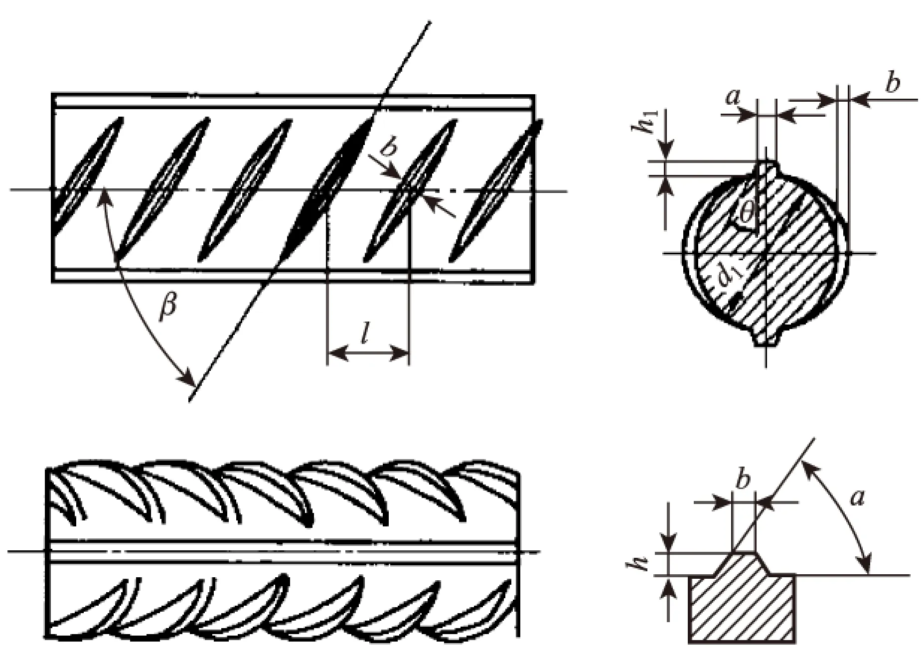
图1 不锈钢钢筋的形状尺寸示意Fig.1 Schematic diagram of shape and dimensions of stainless steel bar
2 平均黏结应力对比试验
钢筋与混凝土的平均黏结力采用无横向配筋的立方体中心拔出试验方法,试件混凝土块尺寸为150 mm×150 mm×150 mm,022Cr22Ni5Mo3N(2205),06Cr17Ni12Mo2(316L),HRB335这 3种钢筋均同样埋于混凝土中心,试件构造见图2,为避免混凝土试块局部破坏,在混凝土的两端各25 mm用塑料套管将钢筋与混凝土隔离。混凝土设计强度分别为C30,C40,C50,实测混凝土试块强度平均值见表3。
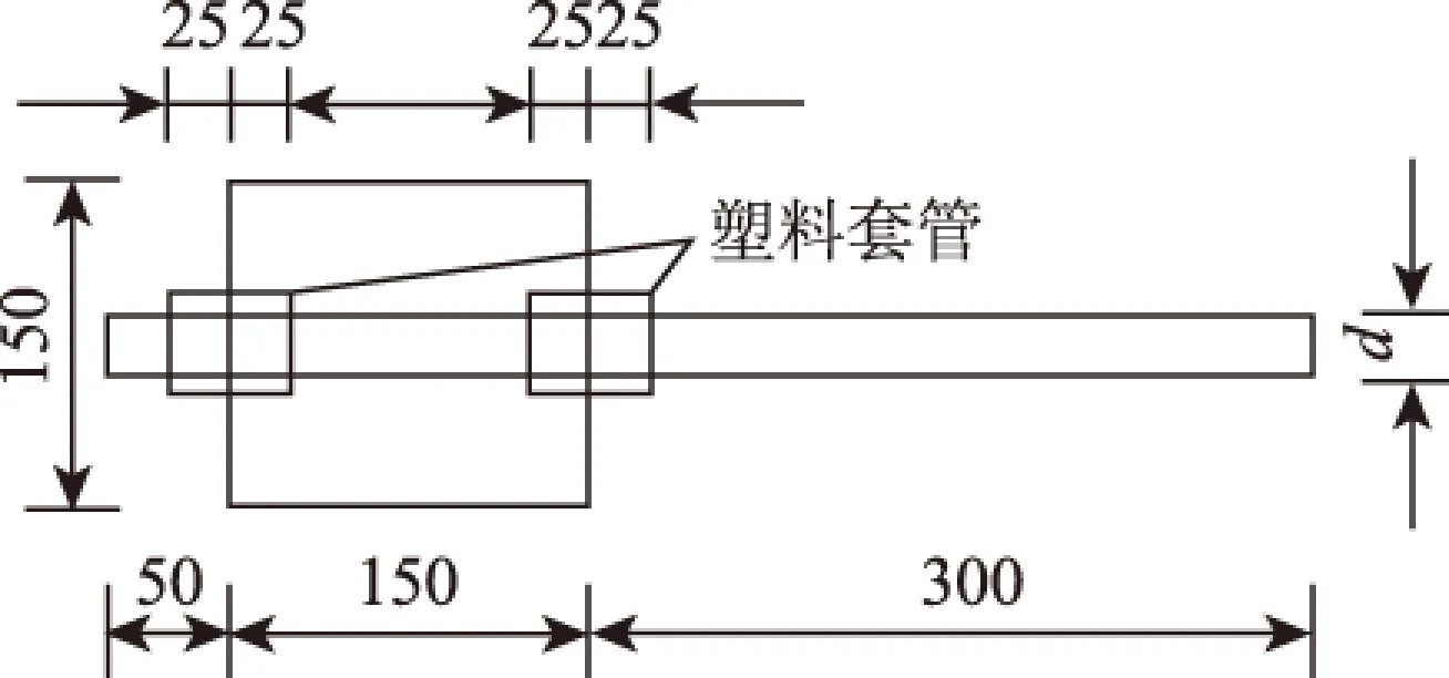
图2 平均黏结力试件尺寸(单位:mm)Fig.2 Dimensions of specimen with average bonding force(unit:mm)

混凝土标号C30C40C50抗压强度/MPa525561166991
平均黏结力试验试件破坏形式有拔出和劈裂两种(图3),小直径钢筋以拔出破坏为主,大直径钢筋全部为劈裂破坏,破坏形式与钢筋种类没有明显关系。拔出破坏是在钢筋拉拔过程中试块没有开裂,钢筋与混凝土试块在接合面发生相对滑移,钢筋直接从混凝土试块中拔出;劈裂破坏是在钢筋拉拔过程中随拉拔力逐渐增大,首先在混凝土试块拉拔端侧面出现裂缝,裂缝很快向自由端发展,直至试块劈裂,钢筋与混凝土黏结力消失。
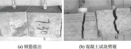
图3 平均黏结力试验试件破坏形式Fig.3 Specimen failure modes in average bond force test
不锈钢筋与混凝土的平均黏结力试验结果见表4,表中不锈钢筋与混凝土平均黏结应力τ由式(1)计算
(1)
式中,τ为钢筋与混凝土的平均黏结应力;F为破坏荷载;d为钢筋直径;la为钢筋和混凝土的黏结长度。

(2)
式中,τi为同编号各试件钢筋与混凝土的平均黏结应力;n为同编号试件数量。
各规格钢筋在不同混凝土强度下的平均黏结应力的平均值见图4,由表4、图4可知,各规格钢筋与混凝土的平均黏结应力都随着混凝土强度的增大而增大;同直径的3种钢筋虽然强度相差较大,但与混凝土的平均黏结应力相差不大,即钢筋强度对钢筋与混凝土的平均黏结应力影响不明显,说明不锈钢筋与混凝土的平均黏结应力与普通钢筋没有明显差别。考虑到不锈钢筋试验数据较少、应用经验不足,不锈钢筋与混凝土的平均黏结应力可暂按规范中普通钢筋与混凝土的平均黏结应力计算。
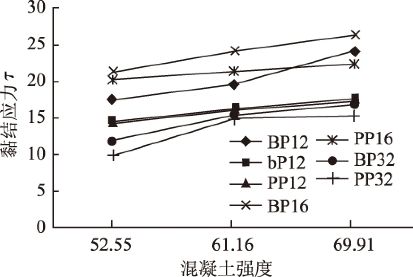
图4 各规格钢筋在不同混凝土强度下的平均黏结应力的平均值(单位:MPa)Fig.4 Average values of average bonding stresses for all sized steel bars with different concrete strengths(unit:MPa)
直径16 mm钢筋与混凝土的平均黏结应力最大,直径12 mm钢筋与混凝土的平均黏结应力次之,直径32 mm钢筋与混凝土的平均黏结应力最小。这是由于钢筋直径越大,钢筋与混凝土黏结应力在混凝土试块中的影响范围越大,一般认为可以影响到10倍钢筋直径的范围,而试样的混凝土尺寸为150 mm×150 mm×150 mm,对于直径32 mm的钢筋与混凝土平均黏结应力试块,钢筋与混凝土的黏结应力影响范围已超出了混凝土试块尺寸,因此其黏结应力明显小于直径为12 mm和16 mm的钢筋的黏结应力。
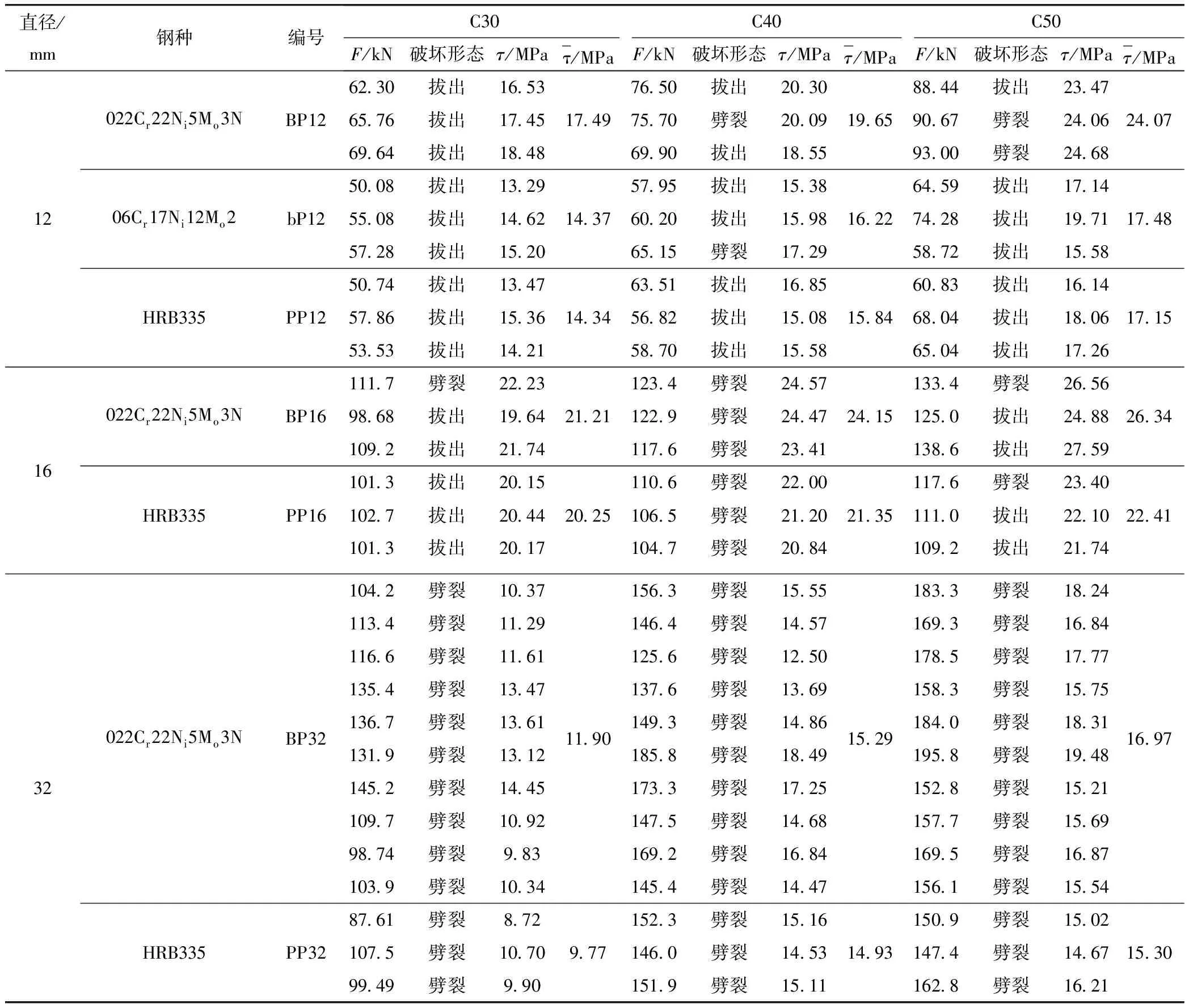
表4 混凝土平均黏结力试验结果
3 黏结力分布对比试验
钢筋与混凝土的黏结力分布同样采用无横向配筋的立方体中心拔出试验方法,C30混凝土试块尺寸160 mm×160 mm×160 mm,试块中心埋设直径16 mm的022Cr22Ni5Mo3N(2205)不锈钢带肋钢筋和HRB335普通带肋钢筋,满足混凝土试块尺寸是钢筋直径10倍的标准要求,试件构造见图5。为避免混凝土试块局部破坏,在混凝土的两端各20 mm用塑料套管将钢筋与混凝土隔离。实测3个混凝土试块强度平均值为50.09 MPa。
为减少钢筋表面变化对接合界面的影响,022Cr22Ni5Mo3N(2205)不锈钢筋和HRB335普通钢筋均沿纵轴线将其切割成两瓣,每瓣钢筋的中心铣出一个凹槽,在槽内贴应变片并引出导线,再用环氧树脂把两半钢筋粘在一起,恢复原貌(图6),应变片在试件中的位置及编号见图7。
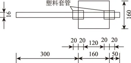
图5 黏结力分布试验试块示意图(单位:mm)Fig.5 Schematic diagram of block specimen for bonding force distribution test(unit:mm)

图6 钢筋开槽内贴应变片示意图(单位:mm)Fig.6 Schematic diagram of built-in strain gauge of open slotted steel bar(unit:mm)

图7 应变片分布示意图(单位:mm)Fig.7 Schematic diagram of strain gauge distribution(unit:mm)
各试件沿长度方向分布的钢筋应力试验结果见表5,由表看出两种钢筋的应力沿长度方向的分布大致相同,试件C30BF16/3(022Cr22Ni5Mo3N(2205)不锈钢筋)、C30PF16/1(HRB335普通钢筋)在不同荷载下钢筋应力沿长度方向的分布对比见图8,加载端钢筋应力最大,自由端钢筋应力最小,钢筋应力随加载端距离的增大而迅速减小。
各荷载下不同位置处钢筋与混凝土的黏结应力τs可根据式(3)求得
(3)
式中,τs为钢筋与混凝土的黏结应力;σi,σi+1为相邻应变片的钢筋应力;As为钢筋面积;u为钢筋周长;l为第i,i+1应变片间的距离;d为钢筋直径;Δσ为相邻应变片的钢筋应力差。

图8 不同荷载下不锈钢筋、普通钢筋应力分布对比Fig.8 Comparison of stress distributions of stainless steel bar and ordinary steel bar under different loads
各试件在不同荷载下的黏结应力τs的分布计算结果见表6,试件C30BF16/3(022Cr22Ni5Mo3N(2205)不锈钢筋)、C30PF16/1(HRB335普通钢筋)黏结应力的分布对比见图9。由图看出,022Cr22Ni5Mo3N(2205)不锈钢筋和HRB335普通钢筋与混凝土的黏结应力分布规律相近,其峰值出现在加载端附近,随着荷载的不断增大,有效黏结长度缓慢增加,应力峰值显著增大,但应力峰值位置基本不变,仅在试样濒临破坏时,应力峰值才向自由端有些许移动。这些规律与其他普通钢筋和混凝土的黏结应力分布试验相同,因此不锈钢筋与混凝土的黏结力分布可暂按普通钢筋与混凝土黏结应力分布规律进行计算。
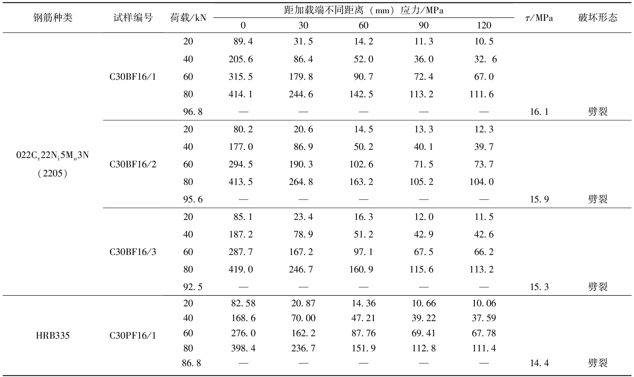
表5 不同荷载下钢筋的应力分布
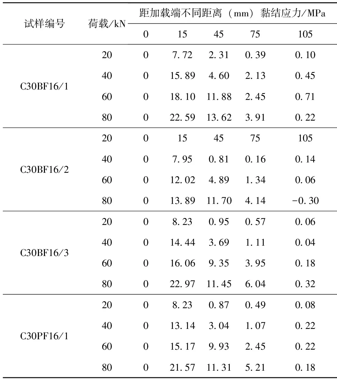
表6 不同荷载下钢筋与混凝土黏结应力分布
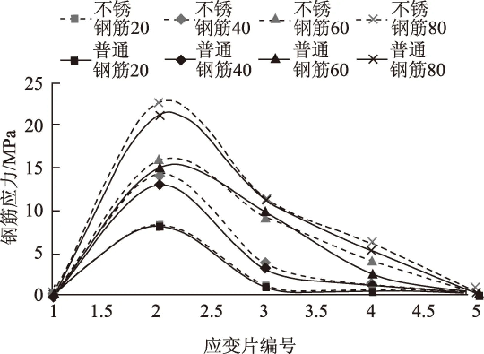
图9 不同荷载下不锈钢筋、普通钢筋与混凝土黏结应力分布对比Fig.9 Comparison of distribution of bonding stresses between stainless steel bar, ordinary steel bar and concrete under different loads
4 结论
022Cr22Ni5Mo3N(2205)、06Cr17Ni12 Mo2 (316L)不锈钢筋这两种钢筋与HRB335普通钢筋相比,前者强度高, 没有明显屈服点, 屈强比大, 弹模低。不锈钢筋、普通钢筋与混凝土的平均黏结应力都随着混凝土强度的增大而增大,同规格不锈钢筋与混凝土的平均黏结力比普通钢筋的稍大,两者与混凝土的平均黏结应力没有明显差别。两种钢筋与混凝土黏结力分布规律基本相同,考虑到不锈钢筋应用经验不足,建议不锈钢筋与混凝土的平均黏结力、黏结力分布暂按普通钢筋进行计算,并按不锈钢筋强度调整不锈钢筋的锚固、搭接等构造措施尺寸。
[1] 张劲泉,李承昌,郑晓华,等. 不锈钢筋混凝土结构研究[M]. 北京:人民交通出版社,2015. ZHANG Jin-quan, LI Cheng-chang, ZHENG Xiao-hua, et al. Study on Structure of Stainless Steel Reinforced Concrete [M]. Beijing: China Communications Press, 2015.
[2] GEDGE G. Structural Uses of Stainless Steel: Building and Civil Engineering[J].Journal of Constructional Steel Research,2008,64(11): 1194-1198.
[3] 梁爱华,VAN DEN BERG G J.不锈钢钢筋用于混凝土的研究[J].建筑技术,2000,31(2):105-107. LIANG Ai-hua, VAN DEN BERG G J.A study and Research of Stainless Steel in Concrete Structure [J]. Architecture Technology, 1999,31 (2): 105-107.
[4] 张国学,吴苗苗. 不锈钢钢筋混凝土的应用及发展[J].佛山科学技术学院学报:自然科学版,2006,24(2):10-13. ZHANG Guo-xue, WU Miao-miao. Application and Development of Stainless Steel Rebars for Reinforced Concrete Structures [J]. Journal of Foshan University:Natural Science Edition, 2006, 24 (2): 10-13.
[5] 袁焕鑫,王元清,石永久. 不锈钢筋混凝土初探及应用前景[J].建筑科学,2011,27(5):101-105. YUAN Huan-xin, WANG Yuan-qing, SHI Yong-jiu. Preliminary Study and Application Prospect of Stainless Steel Reinforced Concrete [J] .Building Science, 2011,27 (5): 101-105.
[6] 骆鸿,董超芳,肖葵,等. 节镍型不锈钢钢筋在混凝土环境中腐蚀研究现状及进展[J].表面技术,2015,44(3):63-67.
LUO Hong, DONG Chao-fang, XIAO Kui, et al. Research Status and Progress on Corrosion of the Low-nickel Stainless Steel Rebar in the Concrete Environment [J]. Surface Technology 2015, 44 (3): 63-67.
[7] 耿会涛,赵西文,李清富.某大桥桥墩防腐工程方案优选[J].河南建材,2012(1):29-31. GENG Hui-tao, ZHAO Xi-wen, LI Qing-fu. Optimal Selection of Anti-corrosion Engineering Scheme for a Bridge’s Piers [J]. Henan Building Materials, 2012 (1): 29-31.[8] 王玉倩,程寿山,李万恒,等.国内外混凝土桥梁耐久性指标体系调查分析[J].公路交通科技,2012,29(2):67-72. WANG Yu-qian,CHENG Shou-shan, LI Wan-heng,et al. Investigation and Analysis on Durability Index System of Domestic and Foreign Concrete Bridges[J]. Journal of Highway and Transportation Research and Development, 2012, 29 (2): 67-72.
[9] BS 6744:2001+A2:2009,Stainless Steels Bars for the Reinforcement of and Use in Concrete. Requirements and Test Methods[S].
[10]ASTM A955/A955M:2004a, Standard Specification for Deformed and Plain Stainless: Steel Bars for Concrete Reinforcement[S].
[11]BS EN 10088-3-2005, Stainless Steels-Part 3: Technical Delivery Conditions for Semi-finished Products, Bars, Rods, Sections and Bright Products of Corrosion Resisting Steels for General Purposes [S].
[12]NS3576-2:2009,Steel for Reinforcement of Concrete-Part 2: Ribbed Bars [S].
Bonding Performance of Stainless Steel Bars and Concrete
LI Cheng-chang1,HE Wei-nan2,LU Jie2,GENG Hui-tao3
(1. Research Institute of Highway, Ministry of Transport, Beijing 100088, China;2. Shaoxing Highway Administration Bureau, Shaoxing Zhejiang 312035, China;3. Zhengzhou University, Zhengzhou Henan 450001, China)
In order to discuss the bonding force and distribution between stainless steel bar and concrete, the comparative test on the average bonding force, the bonding force distribution between ribbed stainless steel bar, ordinary ribbed steel bar and concrete is carried out. The test result of the average bonding forces between these ribbed steel bars and concrete shows that the average bonding forces between all kinds of steel bars and concrete increase with the increase of concrete strength, while the effect of the steel bar strength on the average bond stress between steel bar and concrete is not obvious, indicating that there is no significant difference between the average bonding stress of stainless steel bar and concrete and that of ordinary steel bar and concrete. The test result of the bonding force distribution between ribbed stainless steel bar, ordinary ribbed steel bar and concrete shows that (1) the distribution law of bonding stress between stainless steel bar and concrete is similar to that between ordinary steel bar and concrete, and the peak of the bonding stress appeares near the loading end; (2) with the constant increase of the load, the peak value of the stress increases, but the position is almost the same, and the effective bonding length increases slowly, the stress peak moves to the free end slightly only when the specimen is near to failure. The similarities and differences of the bonding between the two kinds of bar and concrete are analyzed. The calculation method of initial bonding force and the construction measures for the stainless steel bar applied to the concrete members are put forward.
bridge engineering; bonding between stainless steel bar and concrete; bonding force test; average bonding force; bonding force distribution
2016-02-26
交通运输部科技项目(2011 318 223 880)
李承昌(1963-),男,山东新泰人,工程应用研究员.(chch.li@rioh.cn)
10.3969/j.issn.1002-0268.2016.12.003
U448.34
A
1002-0268(2016)12-0015-06

