Numerical study of aerodynamic characteristics of FSW aircraft with different wing positions under supersonic condition
Lei Juanmian,Zhao Shuai,Wang Suozhu
School of Aerospace Engineering,Beijing Institute of Technology,Beijing 100081,China
Numerical study of aerodynamic characteristics of FSW aircraft with different wing positions under supersonic condition
Lei Juanmian*,Zhao Shuai,Wang Suozhu
School of Aerospace Engineering,Beijing Institute of Technology,Beijing 100081,China
This paper investigates the influence of forward-swept wing(FSW)positions on the aerodynamic characteristics of aircraft under supersonic condition(Ma=1.5).The numerical method based on Reynolds-averaged Navier–Stokes(RANS)equations,Spalart–Allmaras(S–A)turbulence model and implicit algorithm is utilized to simulate theflow field of the aircraft.The aerodynamic parameters and flow field structures of the horizontal tail and the whole aircraft are presented.The results demonstrate that the spanwise flow of FSW flows from the wingtip to the wing root,generating an upper wing surface vortex and a trailing edge vortex nearby the wing root.The vortexes generated by FSW have a strong downwash effect on the tail.The lower the vertical position of FSW,the stronger the downwash effect on tail.There fore,the effective angle of attack of tail becomes smaller.In addition,the lift coefficient,drag coefficient and lift–drag ratio of tail decrease,and the center of pressure of tail moves backward gradually.For the whole aircraft,the lower the vertical position of FSW,the smaller lift,drag and center of pressure coefficients of aircraft.The closer the FSW moves towards tail,the bigger pitching moment and center of pressure coefficients of the whole aircraft,but the lift and drag characteristics of the horizontal tail and the whole aircraft are basically unchanged.The results have potential application for the design of new concept aircraft.
1.Introduction

Nomenclature CL Lift coefficient CD Drag coefficient Cp Pressure coefficient L/D Lift–drag ratio¯xcp Center of pressure coefficient LB Length of body,m DB Diameter of cylindrical body,m Χ Swept angle l Span,m λ Aspect ratio α Angle of attack Initials B Body of aircraft T Tail of aircraft W Wing of aircraft
As the spanwiseflow of forward-swept wing(FSW)flows from the wingtip to the wing root,the boundary layer of wing root grows thicker,thus the flow separation initially occurs at the wing root.There fore,FSW solves the wingtip stalling problem,improving the aerodynamic efficiency and maneuverability of aircraft.Due to these advantages,FSW technology was introduced into engineering application be fore and during the Second World War.For example,Junkers Company designed the Ju-287 jet bomber in 1940s,which was a typical FSW aircraft at that time.With the increase of Mach number,FSW technology encountered a series of problems,such as aeroelastic divergence and yaw instability.The development of material and control technology helped FSW aircraft enter a new stage.Grumman Corporation built two X-29 technology demonstrators in 1980s and Sukhoi Company showed the Su-47 fighter prototype in 1997;both of them are new representatives of FSW aircraft.In addition,FSW technology has a wide application in guided weapons;the Fire Shadow loitering munition of MBDA Company adopts FSW con figuration to save space and get better aerodynamic characteristics.
Researchers have investigated the aerodynamic characteristics of FSW aircraft in many respects.In order to optimize theflow field structure and improve the aerodynamic efficiency of FSW aircraft,researchers proposed the canard-FSW con figuration.Behrbohm1found that close-coupled canard wing configuration has many advantages.The aerodynamic interference between canard vortex and wing vortex is favorable and can obviously improve the aerodynamic performance of aircraft.Breitsamter and Laschka2investigated the vortical flow field structure of FSW con figurations by experimental method.Compared with the back-swept wing(BSW)con figuration,the FSW con figuration has a bigger lift-drag ratio under subsonic condition.The leading edge vortex of FSW is generated rotating oppositely to the wingtip vortex at moderate angle of attack.The trailing edge vortex of FSW has the same rotational direction with the wingtip vortex.Zhang et al.3,4investigated the aerodynamic characteristics of canard-FSW con figurations by numerical method.According to their study,the aerodynamic interference and coupling effect between canard and wing have great influences on the aerodynamic characteristics of aircraft.The canard vortex can induce a favorable interference onto the main wing,controlling the separation of boundary layer from the leading edge.Owens and Perkins5studied the aerodynamic characteristics of horizontal tandem wing con figuration by experimental method.Compared with the horizontal two-surface con figuration(FSW and tail),the three-surface con figuration(FSW,tail and canard)provides better longitudinal control ability.Wang et al.6studied the longitudinal aerodynamic characteristics of canard-FSW con figuration by experimental method.The conclusions indicate that the close-coupled canard wing con figuration is helpful to increase the lift coefficient and the stalling angle of FSW.Consequently,the maneuverability of aircraft can be improved greatly.

Fig.1 Forward-swept wing(FSW)aircraft.

Table 1 Geometric parameters of FSW aircraft.

Fig.2 Half of FSW model with structured grid.
Variable FSW configuration can improve the aerodynamic characteristics of aircraft at subsonic,transonic and supersonic conditions respectively.Liu et al.7–9investigated the flow mechanism of variable FSW configuration by numerical method.According to their study,the orthogonal wing can achieve greater lift-drag ratio while taking of f and landing under subsonic condition.FSW configuration can improve the stalling characteristics of aircraft under transonic condition.BSW configuration can decrease the shock wave drag during chasing and escaping under supersonic condition.Sun et al.10per formed a numerical study on the aerodynamic characteristics of W-shaped tailless configuration.Their results show that the performance of W-shaped tailless configuration is excellent,and has a good prospect for development.Xiao and Wang11studied the aerodynamic characteristics of W-shaped tailless configuration by numerical method.According to their study,the flow separation of FSW initially occurs at wing root,thus the control surfaces nearby wingtip have good operating efficiency.

Fig.4 Lift coefficient of tail,(CL)T-α.
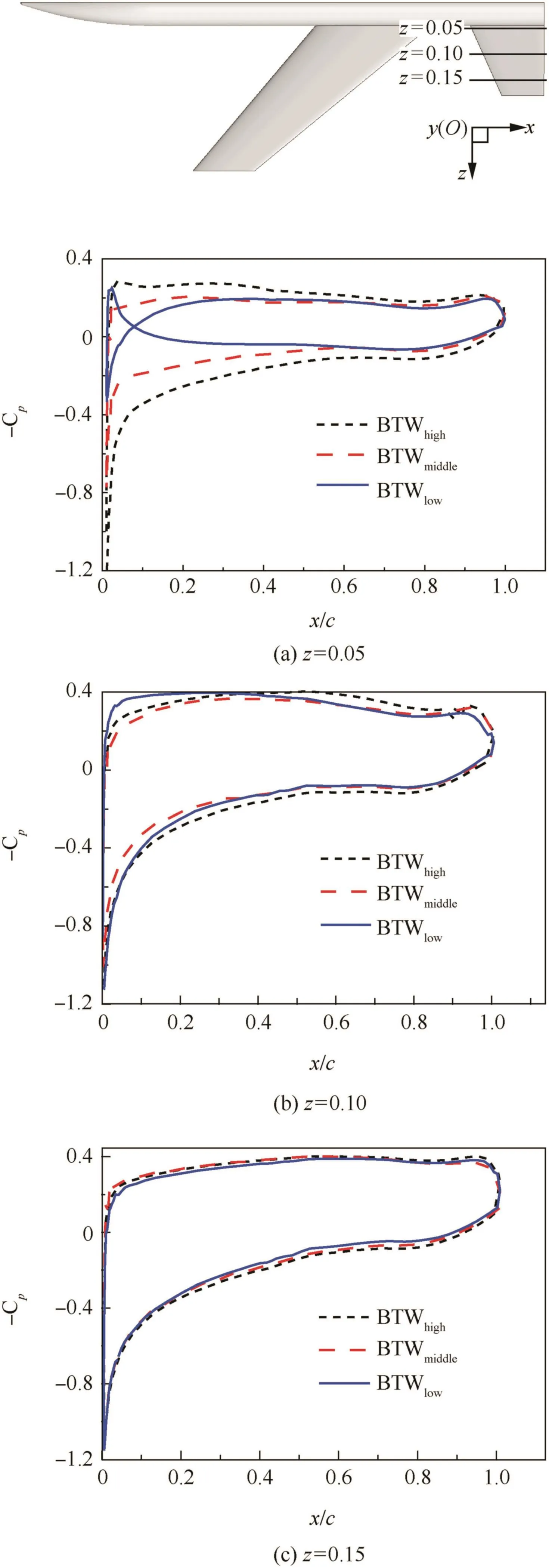
Fig.5 Pressure distributions on the tail,α =12°.

Fig.6 Pressure distributions on the tail,z=0.05,α =12°.
Theflow separation nearby the root of FSW can be well controlled by proper shape modification.Traub and Lawrence12carried out a comparative study between FSW configuration and BSW configuration by experimental method.The forward extension(a strake)is beneficial when used with FSW but detrimental when used with BSW.Zhang and Laschka13,14investigated the flow control approaches of FSW by experimental method.They found that the closecoupled canard wing and back-swept strake can restrict the flow separation of FSW,thus improve the aerodynamic characteristics of FSW aircraft enormously.
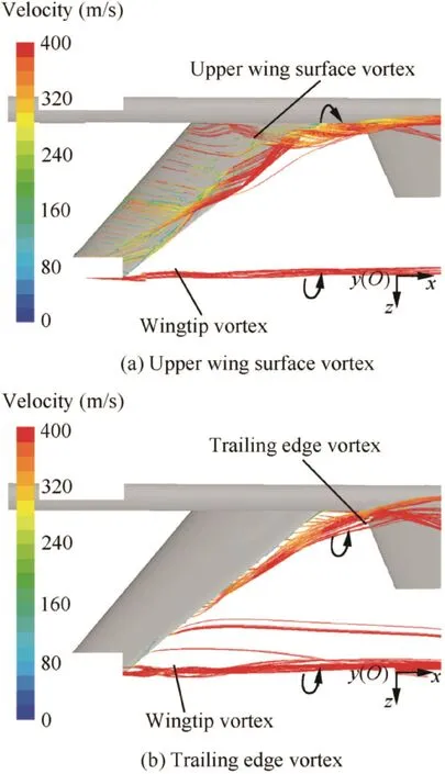
Fig.7 Streamlines of FSW,α =12°.
Tail is important control surface and stabilizer of aircraft.It has great influence on the maneuverability and stability of aircraft.So it is necessary to study the aerodynamic characteristics of tail.As far as we know, for the common con figuration with FSW,there is no study on the aerodynamic characteristics of horizontal tail and whole aircraft under supersonic condition.As a supplementary study,this research investigates the aerodynamic characteristics of the horizontal tail and the whole aircraft with different FSW positions.The paper is organized in the following way:Section 2 shows the computational model and numerical method.Section 3 gives out the calculation results and analysis.The conclusions of this study are presented in Section 4.
2.Numerical method and calculating model
2.1.Governing equations
In this paper,thefinite volume method is used to solve the Navier–Stokes equations,which can be written as

where H is the source term,W,F and G are defined as

Fig.8 Streamlinesperpendicularto bodyaxis,x=0.94,α =12°.

Here ρ,E,and p are the density,total energy per unit mass,and pressure of the fluid,respectively.v is the velocity of fluid,and u,v,w are the velocity components.τ is the viscous stress tensor,and τxi,τyi,τzi,τijare the tensor components.i,j,k are the unit vectors and q is the heat flux.
Total energy E is related to the total enthalpy H by

2.2.Turbulence model
The numerical method in this paper uses the Spalart–Allmaras(S–A)turbulence model,which is a relatively simple one-equation model that solves a modeled transport equation for the kinematic eddy(turbulent)viscosity.The S–A model was designed specifically for aeronautics and astronautics applications involving wall-bounded flows and has been shown to give good results for boundary layers subjected to adverse pressure gradients.Moreover,the computational complexity of the S–A model is small and its rate of convergence is fast.
The transported variable~v in the S–A model is identical to the turbulent kinematic viscosity except in the near-wall(viscosity-affected)region.The transport equation for~v is

Fig.9 Drag coefficient of tail(CD)Tvs angle of attack α.

Table 2 Drag coefficient of tail,α =12°.
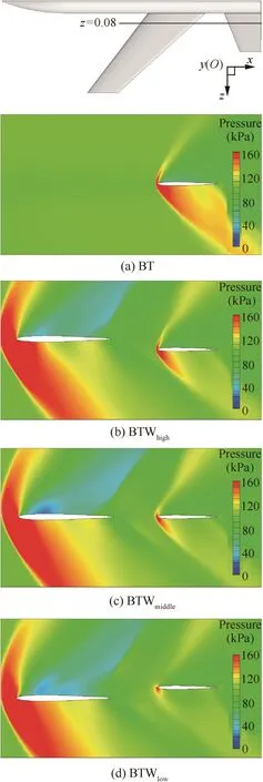
Fig.10 Pressure contours of the z=0.08 section,α =12°.

where Gvis the production of turbulent viscosity and Yvthe destruction of turbulent viscosity that occurs in the near-wall region due to wall blocking and viscous damping.σ~vand Cb2are the constants and~v is the molecular kinematic viscosity.μ is the dynamic viscosity of thefluid.
2.3.FSW models and computational conditions
As shown in Fig.1(a),the FSW configuration is composed of body(B),wing(W)and tail(T).According to Table 1,which shows the geometric parameters of each part.

Fig.11 Lift-drag ratio of tail(L/D)Tvs angle of attack α.
Fig.1(b)is the left view of body with different FSW positions.The letters ‘B”,‘T” and ‘W” represent the body,tail and wing respectively.The subscripts‘high”,‘middle”,‘low”,‘front” and ‘back” represent different positions of FSW.A simple configuration named BT(Body and Tail)is added to study the aerodynamic characteristics of aircraft with and without wing contrastively.
The Mach number,static pressure and temperature are Ma=1.5,P=101325 Pa and T=300 K respectively.The range of angle of attack α is 0°–12°.The length of body LB=1 m is used as the reference length,and the cross section area of cylindrical body Sref=0.0064 m2is used as the reference area.
2.4.Grid and boundary conditions
As shown in Fig.2,half of the FSW model is utilized to save the computing resources and improve the computational efficiency.The structured grid is used to discrete the computational domain.The pressurefar-field boundary condition is adopted for the outer boundary of computational domain.The symmetry boundary condition is imposed on the longitudinal symmetrical plane.The no-slip wall boundary condition is applied on the surface of aircraft.

Fig.12Center of pressure coefficient of tailvs angle of attack α.

Fig.13 Aerodynamic characteristics of the whole aircraft.
2.5.Validation of computational method
In order to validate the accuracy of the computational method,the viscous flow field of ONERA-M6 wing is calculated under the conditions of Ma=0.8395,Re=1.172×10⁷and α =3.06°.Fig.3 shows the pressure distribution curves of ONERA-M6 wing surface at 20%and 90%spanwise sections.The calculation results agree well with the experimental data,15which validates the accuracy of the computational method in this paper.Moreover,the calculation method could capture the local shock wave of the wing,which means it is suitable for low supersonic conditions.
3.Results and analysis
3.1.Aerodynamic characteristics of FSW aircraft with different vertical wing positions
The flow field of aircraft with different FSW vertical positions was calculated at Ma=1.5.Fig.4 shows the lift coefficient of a pair of horizontal tails.Compared with the tail of FSW configurations,the tail of BT con figuration has a bigger lift coefficient at the same angle of attack.For the con figurations with FSW,the lower the vertical position of FSW,the smaller the lift coefficient of tail.
Fig.5 shows the pressure distribution curves of tail surface at α =12°.Normally,the upper tail surface has a smaller pressure coefficient than the lower tail surface,generating a positive normal force.According to Fig.5(a),compared with the tail of BTWmiddle,the tail of BTWhighhas a bigger pressure difference and positive normal force.
According to Fig.6,which shows the details of Fig.5(a),the upper tail surface of BTWlowhas a bigger pressure coefficient than the lower tail surface.Consequently,the tail root of BTWlowgenerates a negative normal force and decreases the total normal force of tail.As is known,normal force makes a great contribution to lift.
Based on the above analysis,the lift coefficient of the tail of BTWhighis the biggest,and the lower the vertical position of FSW,the smaller lift coefficient of tail.This agrees well with the regularity in Fig.4.
As shown in Fig.7,the spanwise flow of FSW flows from the wingtip to wing root,generating an upper wing surface vortex and a trailing edge vortex nearby the wing root and tail root.There fore,the vortexes induced by FSW have a great influence on the aerodynamic characteristics of the tail root.Fig.7 also shows the rotational direction of the vortexes;the trailing edge vortex has the same rotational direction with the wingtip vortex.On the contrary,the upper wing surface vortex has an opposite rotational direction.

Fig.14 Aerodynamic characteristics of horizontal tail.
Fig.8 displays the streamlines of the cross-section which is perpendicular to the body axis at the position of x=0.94(x/LB=94%).For the BT configuration without FSW,there is a leeward side vortex above the tail and a windward side vortex below the tail.For the configurations with FSW,such as BTWhighand BTWmiddle,there is an upper wing surface vortex and a trailing edge vortex above the tail,and a windward side vortex below the tail.The flow field structure of the tail of BTWlowconfiguration is similar to the formers,but the trailing edge vortex is divided into two parts by the horizontal tail.As shown in Fig.8(d),the strength of the trailing edge vortex under the tail is stronger than the trailing edge vortex on the tail.Thus the upper tail surface has a bigger pressure coefficient than the lower tail surface,generating a negative normal force at the tail root.
In summary,both Figs.5 and 8 demonstrate that the vortexes induced by FSW have a significantly downwash effect on the tail,especially on the tail root.The lower the vertical position of FSW,the stronger the downwash effect on the tail;meanwhile the lift coefficient of tail decreases.
The drag coefficient of a pair of horizontal tails is shown in Fig.9.In the angle of attack range of 0–4°,the drag coefficient of the tail of BTWmiddleis the smallest.But in the angle of attack range of 6–12°,the lower the vertical position of FSW,the smaller the drag coefficient of tail.
According to Table 2,at the angle of attack α =12°,the pressure drag coefficient of tail decreases with FSW moving downward,but thefriction drag coefficient of tail is basically unchanged.Consequently,the total drag coefficient of tail decreases and this agrees well with the regularity in Fig.9.
It is known that the shock wave makes a great contribution to the total drag under supersonic condition.Fig.10 gives out the pressure contours of the z=0.08 longitudinal section,which shows the in fluence of FSW on the shock wave strength of tail.As shown in Fig.10,at the position of z=0.08,the lower the vertical position of FSW,the weaker the shock wave strength.In addition,the pressure drag coefficient of tail becomes smaller,and the total drag coefficient of tail decreases.
相较于现代医学,中医辨证施治则可通过抑制气道重塑、调节炎性因子、调节体内免疫功能、改善其血流动力学状态、纠正氧化与抗氧化失衡状态、影响激素变化等方式对稳定期慢性阻塞性肺疾病产生发展多环节进行多靶点、多途径调节,从而延缓稳定期慢性阻塞性肺疾病患者病情进展,提升本病患者的生存质量。有研究证实,对稳定期慢性阻塞性肺疾病患者进行中西医结合治疗的临床效果更佳[24]。
In a word,Table 2 and Fig.10 indicate the same thing,the flow of FSW has a great effect on the pressure drag of tail.The pressure drag and total drag coefficients of tail decrease with the FSW moving downward.
As shown in Fig.11,in the angle of attack range of 0–10°,the lower the vertical position of FSW,the smaller lift-drag ratio of tail.

Fig.15 Pressure contours of the z=0.08 longitudinal section,α =12°.
Fig.12 shows the center of pressure coefficient of tail,which is defined as

where(xcp)Tis the chordwise distance between the leading edge of tail root and the center of pressure of tail,and b0the length of the root chord of tail.It can be seen from Fig.12,the lower the vertical position of FSW,the bigger the center of pressure coefficient of the tail.
The aerodynamic characteristics of the whole aircraft are shown in Fig.13.At a high angle of attack,the lower the vertical position of FSW,the smaller the lift and drag coefficients of the whole aircraft.Moreover,the center of pressure moves forward gradually.
3.2.Aerodynamic characteristics of FSW aircraft with different longitudinal wing positions
Fig.14 shows the effects caused by the longitudinal positions of FSW on the aerodynamic characteristics of the horizontal tail.It can be observed that the longitudinal positions of FSW affect the lift and drag characteristics little.Fig.14(d)shows that the pressure centers of the tail of BTWfrontand BTWmiddleare similar,and both of them locate in front of the pressure center of the tail of BTWback.
Shock wave makes a great contribution to the total drag under supersonic condition.Fig.15 gives the pressure contours of the z=0.08 longitudinal section,which shows the influence of FSW on the shock wave strength of tail.As shown in Fig.15,with FSW moving towards tail,the shock wave strength of the horizontal tail is basically unchanged,thus the pressure drag coefficient of tail changes little.In addition,the total drag coefficient of tail is basically unchanged.
4.Conclusions
(1)The spanwiseflow of FSW flows from the wingtip to wing root,generating an upper wing surface vortex and a trailing edge vortex nearby the wing root.
(2)The vortexes generated by FSW have a strong downwash effect on the tail,especially on the tail root.The lower the vertical position of FSW,the stronger the downwash effect on tail.There fore,the effective angle of attack of tail becomes smaller.In addition,the lift coefficient,drag coefficient and lift-drag ratio of tail decrease,and the center of pressure of tail moves backward gradually.At high angle of attack,the lower the vertical position of FSW,the smaller lift,drag and center of pressure coefficients of the whole aircraft.
(3)The closer the FSW moves towards tail,the bigger pitching moment and center of pressure coefficients of the whole aircraft,but the lift and drag characteristics of horizontal tail and the whole aircraft are basically unchanged.
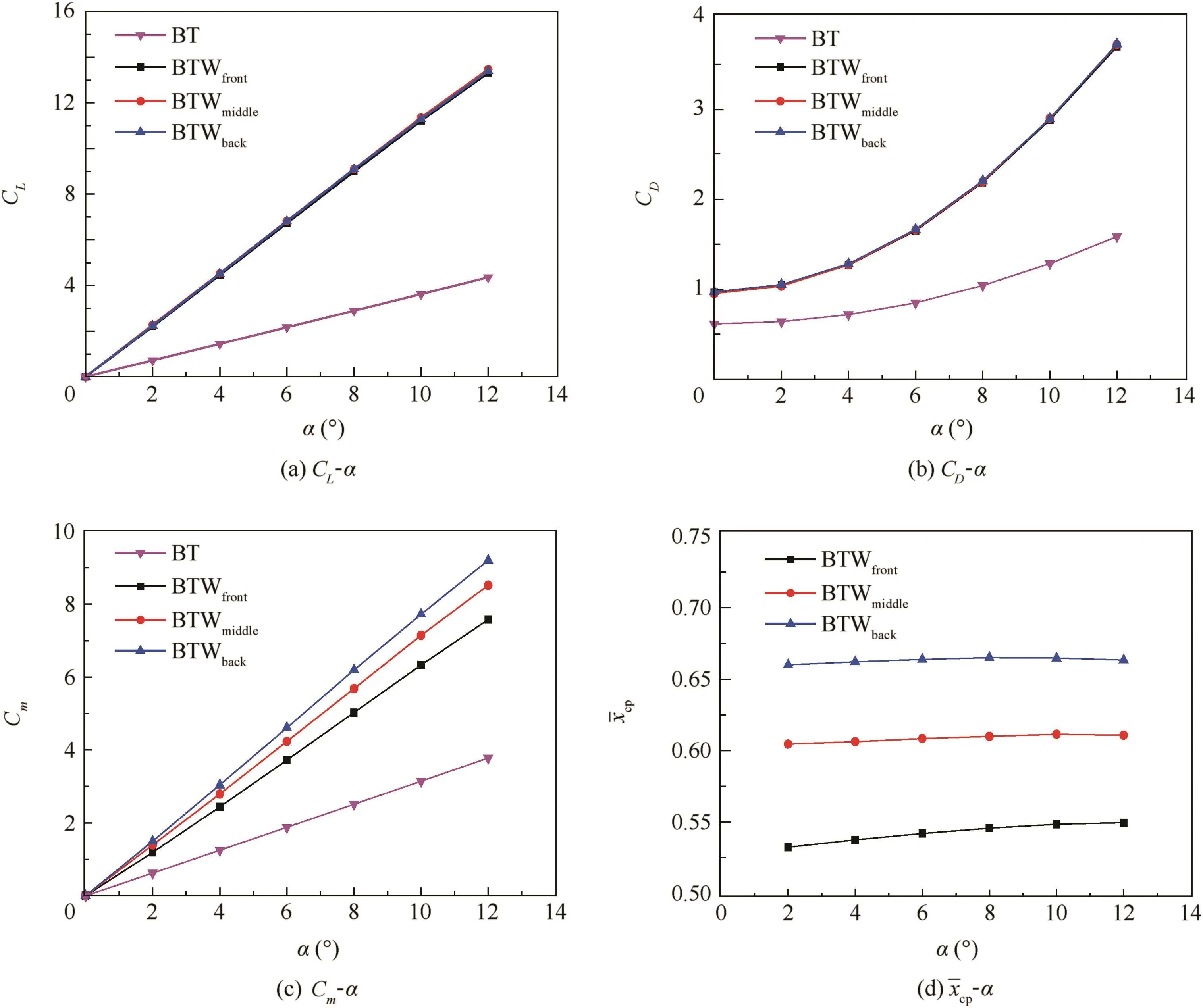
Fig.16 Aerodynamic characteristics of the whole aircraft.
1.Behrbohm H.Basic low speed aerodynamic of short-coupled canard configuration of small aspect ratio.Sweden:Linkoping;1965.Report No.:SAABTN-60.
2.Breitsamter C,Laschka B.Vortical flow field structure at forward swept-wing configurations.J Aircr 2001;38(2):193–206.
3.Zhang GQ,Yu SCM,Chien A,Yang SX.Aerodynamic characteristics of canard- forward sweptwing aircraft configurations.J Aircr 2013;50(2):378–87.
4.Zhang GQ,Yang SX,Xu Y.Investigation of vortex interaction in canard-FSW configurations based on the numerical wind tunnel method.Chin J Aeronaut 2009;23(3):3129.
5.Owens DB,Perkins JN.Stability and control of a three-surface,FSW configuration.J Aircr 1996;33(06):1206–8.
6.Wang JJ,Zhao X,Wang SF,et al.Experimental investigation on longitudinal aerodynamic characteristics of canard-FSW configuration.Acta Aerodynamica Sin 2004;22(2):237–40[Chinese].
7.Liu WF,Wang X,Zhang L.Longitudinal characteristics of the aerodynamic configuration with variable FSW.Flight Dyn 2008;26(4):4–7[Chinese].
8.Liu WF,Wang X,Mi K.A new aerodynamic configuration of UAV with variable FSW.Acta Aeronaut Astronaut Sin 2009;30(5):1–5[Chinese].
9.Liu WF,Wang X,Liu X.Aerodynamic characteristics and flow mechanism of the configuration with variable FSW.Acta Aerodynamica Sin 2010;28(5):559–64[Chinese].
10.Sun J,Zhang BQ,Zhou Z,et al.An innovative W-shaped tailless aerodynamic configuration.J Northwestern Polytech Univ 2004;22(3):265–8[Chinese].
11.Xiao H,Wang LX.Research on control principles and stability characteristics of W-shaped tailless aircraft.Acta Aeronaut Astronaut Sin 2007;28(5):1062–8[Chinese].
12.Traub LW,Lawrence J.Aerodynamic characteristics of forward and aft swept arrow wings.J Aircr 2009;46(4):1454–7.
13.Zhang BQ,Laschka B.Control of separated flow at the root for forward swept wing.Acta Aeronaut Astronaut Sin 1992;13(5):241–6[Chinese].
14.Zhang BQ,Laschka B.On FSW’s aerodynamic characteristics.J Northwestern Polytech Univ 1989;7(3):321–8[Chinese].
15.Schmitt V,Charpin F.Pressure distributions on the ONERA M6-Wing at transonic Mach numbers,experimental data base for computer program assessment.Paris:the Fluid Dynamics Panel Working Group 04;1979.Report No.:AGARD AR-138.
Lei Juanmian is a prof essor in Beijing Institute of Technology.Her main research interests arefluid mechanics and aerodynamics.
Zhao Shuai received his master’s degree at Beijing Institute of Technology in 2016.His main research interest is aerodynamics.
Wang Suozhu finished his postdoctoral work in Beijing Institute of Technology.His main research interests arefluid mechanics and aerodynamics.
27 April 2015;revised 7 January 2016;accepted 7 March 2016
Available online 22 June 2016
Aerodynamic characteristics;
Downwash effect;
Forward-swept wing;
Numerical simulation;
Supersonic flow
©2016 Chinese Society of Aeronautics and Astronautics.Production and hosting by Elsevier Ltd.Thisisan open access article under the CC BY-NC-ND license(http://creativecommons.org/licenses/by-nc-nd/4.0/).
*Corresponding author.Tel.:+86 10 68912414.
E-mail addresses:leijm@bit.edu.cn(J.Lei),zhaoshuai985@126.com(S.Zhao),wangsuozhu@163.com(S.Wang).
Peer review under responsibility of Editorial Committee of CJA.
Production and hosting by Elsevier
http://dx.doi.org/10.1016/j.cja.2016.06.006
1000-9361©2016 Chinese Society of Aeronautics and Astronautics.Production and hosting by Elsevier Ltd.
This is an open access article under the CC BY-NC-ND license(http://creativecommons.org/licenses/by-nc-nd/4.0/).
 CHINESE JOURNAL OF AERONAUTICS2016年4期
- CHINESE JOURNAL OF AERONAUTICS的其它文章
- Numerical simulation of aerodynamic interaction for a tilt rotor aircraft in helicopter mode
- Investigation of MHD power generation with supersonic non-equilibrium RF discharge
- Experimental study on ceramic membrane technology for onboard oxygen generation
- Transition study of 3D aerodynamic configures using improved transport equations modeling
- Numerical investigation of aerodynamic flow actuation produced by surface plasma actuator on 2D oscillating airfoil
- Characterization of component interactions in two-stage axial turbine
